Page is loading ...

iDream/iDream2
iSteam3 Control
PUR100514
07-17
AromaSteam SteamHead
PUR100421
10-15
SteamLinx Mobile App
PUR100518
01-18
AudioSteam3 System
PUR100516
01-18
Square Speakers
PUR100401SQ
05-13
ChromaSteam3 System
PUR100515
01-18
AromaSteam System
PUR100402
08-18
AutoFlush
PUR100200E
10-15
Condensation Pan
PUR100445
10-09

!
C A U T I O N
!
C A U T I O N
mr
.
steam
®
S T E A M H E A D
___________________________________________________________________________________________________________________________________________
I N S TA L L AT I O N I N S T R U C T I O N S
PUR 100421 10.15
mr
.
steam
®
Sussman-Automatic Corp®
[email protected] www.mrsteam.com
43-20 34th Street, Long Island City, NY 11101 tel: 1 800 76 STEAM fax: 718 472 3256
9410 S. La Cienega Blvd. Inglewood CA 90301 tel: 1 800 72 STEAM fax: 310 216 2944
S
team
Supply Pipe
End of pipe to be recessed
1
/4" (without Acrylic Shield)
1
/8" (with Acrylic Shield)
1/8"
m
inimum clearance required
w
hen Acrylic Shield is used.
S
ee installation instructions
p
rovided with the Acrylic Shield.
A
pply with silicone or
equal sealant as required
for moisture seal.
U
se Teflon
®
o
r equal
sealant on pipe threads
Oil Well
STEP 3
STEP 4
STEP 5
Steamhead
(shown with
optional acrylic shield)
Locating Nipple
Drop Ear
Fitting
All drawings are for illustrative purposes only
3”
2
3
/
4
”
3
1
/
2
”
3”
1”
0 3”
7
/
8
”
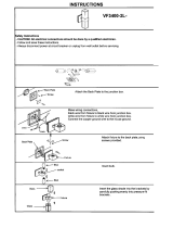
IMPORTANT:
See the Installation and Operation Manual
provided with the steam generator for additional important
steamhead & control installation and operation information.
Installation:
Steam Head (
1
⁄2" NPT)
INSTALLER: Because the steam head and direct
steam emissions are very hot, locate the steam head where incidental
contact by bather with the steam head or direct steam emission cannot
occur.
STEP 1 Locate steam head 6-12 inches above floor, except for:
1. Tub/shower enclosures, install 6 inches above tub top edge.
2. For enclosures with acrylic or other non-heat resistant
flooring install Acrylic Shield Part Number MS-103938.
3. To prevent door seals from deteriorating do not locate the steam
head where direct steam emission would contact door seals.
STEP 2
Install steamhead with the oil well facing up as shown. Hand
tightening is sufficient when teflon or equal pipe thread sealing com-
pound is used.
IMPORTANT NOTE:
to preserve steam head finish, do not use
wrench or other tools to tighten. DO NOT use abrasive cleansers or
chemicals. Use only water with mild soap and a non-abrasive sponge.
Consult with supplier of acrylic, fiberglass and other
non-heat resistant enclosures for recommended steamhead location.
Use Acrylic Shield part number MS-103938. See instructions provided
with steam shield.
STEP 3 Secure a bronze drop ear fitting to a header and run a 1/2"
copper steamline from the steam generator to the drop ear fitting.
Install a temporary nipple (6" or longer)in the drop ear fitting to locate
the steamhead after the wall is finished.
STEP 4 After the wall has been finished, mark on the nipple where the
surface of the wall is. Remove the nipple and measure the portion that
was in the wall (the end to your mark). Subtract
1
⁄
4
" from that dimen-
sion and select a brass nipple of that length to finish the installation.
STEP 5 Wrap teflon tape around the threads of the new nipple and
screw the nipple into the steamhead. Do not use wrenches or tools
which would damage the steamhead's finish. Wrap teflon tape around
the threads of the nipple and screw the nipple and steamhead assem-
bly you just made into the drop ear fitting in the wall. The steamhead
should be flush with the wall and the well must be facing up.

1
INSTALLATION INSTRUCTIONS
SteamLinx Module and Mobile App allows for seamless
control of time and temperature using your smart phone
or mobile device. SteamLinx works with all MrSteam
controls (for MS generators SN 1174000 and up).
Indicates a potentially hazardous
situation, which, if not avoided, may result in
death or serious injury.
Indicates a potentially hazardous
situation, which, if not avoided, may result in
minor or moderate injury or product damage.
is used to address practices not
related to physical injury.
These instructions contain safety alert symbols and panels. These alert symbols
and panels identify potential safety hazards and provide important information
for the installation and use of SteamLinx.
Read the Installation, Operation and Maintenance Manual for Steambath Generator
Systems (PUR100472) before installation of SteamLinx to insure safety and proper
installation of the steam Generator. A free replacement manual is available by
calling MrSteam Customer Service, or it can be downloaded from
mrsteam.com
All drawings for schematic purposes only.
Package Contents:
• SteamLinx A with Integral Cable
• SteamLinx B and Ethernet Cable
• Power Supply and Cable
• Instructions
Cover
Screws
Generator
Cover
Knock-out in
the Generator
Jacket
Connecting SteamLinx A to
the Steam Generator
• Disconnect power to the generator
at the breaker box.
• Locate the SteamLinx A
(with the integral cable).
To prevent shock hazard,
disconnect power at the breaker box before
removing generator cover
• Remove knock-out.
• Remove generator cover.
• Route the SteamLinx A cable
through the knockout
ELECTRICAL SHOCK HAZARD.
MrSteam steam generators are connected
to 240V line voltage and contain live
electrical components. All installation and
service must be performed by a licensed
and qualified electrician.
• Locate the circuit board.
• Plug the SteamLinx A into the
white connector located at the
far left side of the circuit board.
• Replace cover and screws.
• Restore power.
ELECTRICAL SHOCK HAZARD.
MrSteam steam generators are connected
to 240V line voltage and contain live
electrical components. All installation and
service must be performed by a licensed
and qualified electrician.
Circuit
Board

3
4
5
6
Troubleshooting: Blinking LED
Tech Service Contact
Warranty
Connecting SteamLinx to the Internet
• Insure the mobile device is on the WiFi network.
• Download the SteamLinx App from the Apple
Store or Google Play by following prompts.
Sussman-Automatic Corporation
®
I hello@mrsteam.com I www.mrsteam.com
43-20 34th Street, Long Island City, NY 11101 800 76 STEAM
PUR 100518 1.18
CUSTOMER and TECH SUPPORT
Web:
Visit mrsteam.com for additional informaton including
product specifications, locating a device, sizing
calculator, technical downloads and other resources.
Call:
Mon.– Fri.: 8 am - 7 pm
East Coast: 1.800.767 STEAM (8326)
West Coast: 1.800.727 STEAM (8326)
Worldwide: 1.718.937.4500
To view or download the SteamLinx
warranty and register, go to
blog.mrsteam.com/wr
Troubleshooting: Indicator Lights
LEDs
Yellow Blinking units are in pairing mode.
Red Router not detected: problem with
connections, router configuration
or steam generator circuit board.
Green SteamLinx B: router is detected but
is not connecting to the internet.
The indicator light on SteamLinx A
will not be illuminated.
Blue Units are connected correctly.
Units are out of range or not paired
• Turn breaker off.
• Insure SteamLinx A is connected to the steam generator.
• Use a paperclip or similar blunt end object to press the reset
button (above the LED) on SteamLinx B.
• The LED will flash yellow (it stays in pairing mode until it
is paired or powered off).
• Turn the breaker to the steam generator ON, if the two
transmitters are functioning correctly and within range
the LEDs will turn blue.
• If the Blue, Green or Red LEDs are blinking the units are not pairing
because they are out of range. Using an extension cord for power,
move the SteamLinx B closer to SteamLinx A. Disconnect the
ethernet cable (the router connection is not required for this test).
If the LEDs stop blinking this confirms the units were out of range.
Home Router
Power
Supply
Ethernet
Cable (3’)
3’ Cable
2
Connecting SteamLinx B to the Home Router
• Plug the blue ethernet cable provided,
into an ethernet slot on
the back of the
home router.
• Plug the power
supply into a
120V outlet.

AudioSteam
®
Installation, Operation, and Maintenance Manual
mr
.
steam
®
Feel Good Inc.
®
Installation, Operation and Maintenance Manual

READ ME FIRST:
1. Read and follow all instructions within this technical manual.
2. Heed all warnings, cautions, notices, and important notes.
3. Save this technical manual and leave with the homeowner.
ABOUT WARNINGS, CAUTIONS, NOTICES, AND IMPORTANT NOTES:
As you follow the instructions in this technical manual, you will see four types of callouts: WARNINGS, CAUTIONS,
NOTICES, and IMPORTANT NOTES. This blocked information is important for the safe and efficient installation, mainte-
nance, and operation of the AudioSteam. These callouts are described as follows:
SAFETY INSTRUCTIONS:
To prevent personal injury and or product damage, please read the following important safety instructions carefully before
installing the AudioSteam:
• Do not install the AudioSteam near any heat sources.
• Clearance and minimum distance between the AudioSteam and the surrounding structure are not specified as long as
they are sufficient so that the ambient temperature around the apparatus does not exceed 140 °F (60 °C).
• Do not defeat the safety purpose of the polarized and/or grounding type plug. A polarized plug has two blades, with
one wider than the other. A grounding type plug has two blades and a third grounding prong. The wide blade or the
third prong are provided for your safety. If the provided plug does not fit into your outlet, consult an electrician for
replacement of the obsolete outlet.
• Protect the power cord from being walked on or pinched, particularly at plugs, convenience receptacles, and at the point
where the cord exits from the apparatus.
• Only use attachments/accessories specified by the manufacturer.
• All servicing to be performed by qualified service personnel. Servicing is required when the AudioSteam is damaged
in any way, including when the power-supply cord or plug is damaged, liquid is spilled into or objects fall into the
AudioSteam, AudioSteam is exposed to rain or moisture, the AudioSteam does not operate normally, or the AudioSteam
dropped.
• Do not disassemble or alter the AudioSteam in any way.
• Clean the AudioSteam with a dry cloth only. Beware of the application of some products commonly used against cor-
rosion (such as WD-40
®
family products), as some industrial oils can have negative chemical reactions and damage the
housing materials of the AudioSteam. Any other materials that may come in contact with the AudioSteam must be care-
fully evaluated under end-use conditions for compatibility.
2
Indicates a potentially hazardous situation,
which, if not avoided, may result in death
or serious injury.
These instructions are for use by qualified service personnel
only. To reduce the risk of electric shock, do not perform any
servicing, other than that contained in these instructions.
Indicates a potentially hazardous situation,
which, if not avoided, may result in minor
or moderate injury.
Indicates a situation, which, if not avoided,
may result in property damage.
IMPORTANT SAFETY INFORMATION
NOTE: All information in this technical manual is based on the latest product information available at the time of
publication. Sussman-Automatic Corporation reserves the right to make changes at any time without notice.
IMPORTANT NOTE
Indicates information that is especially
relevant to a problem-free installation.
NOTICE
WARNING
!
WARNING
!
CAUTION
!

3
Before installing or connecting the AudioSteam, please read the following:
• To prevent a shock hazard, do not disassemble or alter the AudioSteam.
• To prevent overtemperature shutoff and equipment damage, do not use foam to insulate the
AudioSteam.
• To prevent a shock hazard, turn power off before servicing or changing any cable connections
in the AudioSteam.
• To prevent electric shock hazard and/or water damage to the AudioSteam, all conduits must
be plugged with the included foam blocks.
• To prevent a shock hazard do not install the AudioSteam in a location where it can get wet.
Audiosteam must be installed in a dry, indoor location.
• AudioSteam must be disposed of separately in accordance with local waste disposal legislation.
• Risk of electric shock. Do not leave compartment door open.
• Risk of electric shock. Replace components only with identical components.
• Prevent electrocution. Do not connect any auxiliary components (for example cable, additional
speakers, headphones, additional audio/video components, etc.) to the system.
• These units are not provided or intended to be connected to an outdoor antennae; to prevent
electrocution only use the supplied antennae and install it in accordance with these instructions.
• Opening or removing covers may expose you to dangerous voltage or other risk of injury.
All servicing to be performed by qualified service personnel.
• When the power supply connections or power supply cord(s) are damaged; if water is entering
the audio/video compartment or any electrical equipment compartment area; if the protective
shields or barriers are showing signs of deterioration; or if there are signs of other potential
damage to the unit, turn off the unit and refer servicing to a qualified service personnel.
• This unit should be subjected to periodic routine maintenance (for example, once every 3
months) to make sure that the unit is operating properly.
• Product must be disposed of separately in accordance with local waste disposal legislation.
IMPORTANT SAFETY INFORMATION (cont.)
WARNING
!
WARNING
!

pur 100516 rev 1.18
mr
.
steam
®
Sussman-Automatic Corporation
®
• www.mrsteam.com • [email protected]
43-20 34th Street, Long Island City NY 11101 1 800 76 STEAM fax: 718 472 3256
9410 S. La Cienega Blvd., Inglewood CA 90301 1 800 72 STEAM
fax: 310 216 2944
4
mr
.
steam
®
INSTALLATION, OPERATION, AND MAINTENANCE AudioSteam
®
TABLE OF CONTENTS
INSTALLER INSTRUCTIONS
1. General information ................................................5
Box Contents ................................................................5
AudioSteam
J2
General installation ............................ 5-6
2. Installing AudioSteam ............................................. 7
AudioSteam Dimensions .............................................. 7
Locating and Installing AudioSteam ............................7
3. Connecting AudioSteam .........................................8
Connecting AudioSteam .............................................. 8
Removing the AudioSteam Cover ...............................8
Connecting the FM Antenna and Auxiliary Cord .........9
Connecting Speakers and Subwoofer ..........................9
Connecting AudioSteam to the Steam Generator ....10
Pairing a Bluetooth-Enabled Device .......................... 11
4. AudioSteam Specifications ................................... 12
5. Regulatory Statements ......................................... 13
HOMEOWNER/END-USER INSTRUCTIONS
6. About AudioSteam ............................................... 14
7. Operating AudioSteam .................................... 14-15
8. AudioSteam Warranty........................................... 15

5
Box Contents
AudioSteam General Installation
Figure 1 shows how the AudioSteam interconnects with the
steam generator, iSteam3, and audio speakers.
Figure 2 shows how to use the AudioSteam as a standalone
system within your steam room (i.e., if your steam room does
not use iSteam3).
All drawings are for illustrative purposes only.
1. General Information
AudioSteam
FM antenna
Control cable
INSTALLER INSTRUCTIONS
mr
.
steam
®
INSTALLATION, OPERATION, AND MAINTENANCE AudioSteam
®
IMPORTANT NOTE
AudioSteam only integrates with iSteam3.

Figure 1
Figure 2
Speakers
Speakers
Speaker wire (100 ft max)
Speaker wire (100 ft max)
iSteam3
iTempo,
iTempoPlus,
AirTempo
Grounded wall outlet
Grounded wall outlet
AudioSteam
AudioSteam
Antenna (4 ft)
Antenna (4 ft)
Power cord (6 ft)
Power cord (6 ft)
AudioSteam control cable (30/60 ft)
In-room control cable (30/60 ft)
In-room control cable (30/60 ft)
Steam
generator
Steam
generator
STEAM ROOM
(wet)
STEAM ROOM
(wet)
(dry)
(dry)
All drawings are for illustrative purposes only.
6
INSTALLER
mr
.
steam
®
INSTALLATION, OPERATION, AND MAINTENANCE AudioSteam
®

7
AudioSteam Dimensions
Figure 3 shows the face-on dimensions of AudioSteam.
Figure 4 shows the side-view dimensions of AudioSteam.
Locating and Installing AudioSteam
To prevent water from getting inside the device, AudioSteam should
be mounted on two stable vertical surfaces (e.g., studs) as shown in
Figure 5.
Using screws and washers, firmly attach AudioSteam using the upper
mounting holes, one at a time, on each side of the unit. Repeat the
process for the lower mounting holes (Figure 5).
Figure 3
Figure 4
Figure 5
IMPORTANT NOTES
1. The following materials (not included) are recommended to
install AudioSteam:
• Four #10 screws of appropriate length with round, truss,
or pan head.
• Four washers with 0.5” outer diameter x 0.0625” thick-
ness (12 mm outer diameter x 1.5 mm thickness).
2. To prevent overtemperature shutoff and equipment damage, do
not use foil insulation in front of AudioSteam.
3. Place AudioSteam far from any electrical noise source, such as
variable speed controls and motors, to prevent interference
that will affect audio quality.
4. In the event of an overtemperature condition, AudioSteam
automatically reduces the volume to protect the amplifier from
damage.
5. To prevent overtemperature shutoff, do not locate in an attic or
other location where ambient temperature may reach 140 °F
(60 °C).
A clearance of at least 0.75” (19 mm) is required to ensure free
heat circulation at the back of the unit.
NOTICE
All drawings are for illustrative purposes only.
mr
.
steam
®
INSTALLATION, OPERATION, AND MAINTENANCE AudioSteam
®
2. Installing AudioSteam
INSTALLER
Shock hazard. Do not place the control box in a location where
it can get wet.
WARNING
!

mr
.
steam
®
INSTALLATION, OPERATION, AND MAINTENANCE AudioSteam
®
3. Connecting AudioSteam
8
Connecting AudioSteam
To connect AudioSteam to the steam generator, per-
form one or more of the following connections:
• Connect the FM antenna (included) and auxiliary
cord to AudioSteam.
• Connect speakers and subwoofer to AudioSteam
with speaker wire.
• Connect AudioSteam to the steam genera-
tor’s motherboard or daughterboard with the
AudioSteam control cord.
• Pair a Bluetooth-enabled device to AudioSteam.
Removing the AudioSteam Cover
To remove the AudioSteam cover:
1. Using a Phillips-head screwdriver, remove the two
cover screws from the front of the AudioSteam
(Figure 6), and remove the cover from the unit.
2. Connect the outputs of AudioSteam as shown in
Figure 7.
3. Remove the two foam block inserts from the
inner wiring channels and set aside (Figure 8).
Figure 6
Figure 8
Figure 7
• To reduce the risk of electric shock, do not
remove the screws on the back of AudioSteam.
No user-serviceable parts inside. Refer servicing to
qualified service personnel.
• To prevent electric shock, do not connect
AudioSteam to main power supply while the cover
is removed.
• AudioSteam does not come with speakers
and speaker wiring. The connection between
AudioSteam and the speakers must be “Class 2
Wiring” and installed by qualified personnel.
WARNING
!
Foam block
inserts
Power
Cord
Auxiliary and
FM Outputs
Speaker and
Subwoofer
Outputs
Communication
Port
All drawings are for illustrative purposes only.
INSTALLER

Connecting the FM Antenna
and Auxiliary Cord
1. Plug the included FM antenna into the antenna
output and route the wire through the strain relief
channel as illustrated (Figure 9). For best recep-
tion, fully deploy the antenna in a vertical orienta-
tion outside of the AudioSteam housing.
2. Connect a 1/8” (3.5 mm) stereo audio cord (not
included) to the auxiliary output, and route the
cable through the strain relief channel as illus-
trated (Figure 9). Connect the free end of the
audio cord to a mobile device or digital music
player.
Connecting Speakers
and Subwoofer
1. Connect individual speaker wires — or a 10-pin
MATE-N-LOK adapter with attached wires — to
the speaker outputs. Refer to Figure 10 and
Figure 11 for connector identification.
2. Route the wires through the molded relief chan-
nel. Connect the speaker wires to suitable speak-
ers and subwoofer.
3. Replace the foam block inserts (Figure 9).
4. Secure the cover using the two cover screws.
9
10 9 8 7 6 5 4 3 2 1
Figure 10
Figure 11
Figure 9
Auxiliary
Cord
FM
Antenna
Route
Wires
Replace
Foam
Blocks
CONNECTION IDENTIFICATION COLOR
1 Front Left speaker (+) White
2 Front Left speaker (-) White/Black
3 Front Right speaker (-) Grey/Black
4 Front Right speaker (+) Grey
5 Rear Left speaker (+) Green
6 Rear Left speaker (-) Green/Black
7 Rear Right speaker (-) Purple/Black
8 Rear Right speaker (+) Purple
9 Subwoofer (+) Blue
10 Subwoofer (-) Blue/Black
IMPORTANT NOTES
• If you use individual speaker wires, the rec-
ommended socket crimping contact is an
AWG 14-20 (TE Connectivity part number
350550-3).
• If you use a 10-pin MATE-N-LOK adapter
with attached wires, the required hous-
ing connector is a 10-position Universal
MATE-N-LOK (TE Connectivity part number
926302-3).
mr
.
steam
®
INSTALLATION, OPERATION, AND MAINTENANCE AudioSteam
®
All drawings are for illustrative purposes only.
AudioHome only uses positions 1, 2, 3 & 4
INSTALLER

10
Figure 12
Connecting AudioSteam
to the Steam Generator
To operate the AudioSteam via iSteam3, you must connect the
AudioSteam (Figure 12) to an internal connector in the steam generator.
1. Remove the steam generator cover, and remove knockout
on steam generator.
2. Plug the control cable into the AudioSteam as shown.
3. Connect the control cable directly to the steam generator’s
circuit board (A in Figure 13), OR if an additional accessory
is installed in the steam generator, connect the control cable
to the supplied daughterboard (B in Figure 13).
4. Plug the AudioSteam power cord into a 120V grounded
electrical outlet.
Power Cord
to 120V
Grounded
Outlet
Control Cable
Connection Port
Control Cable
Plug-In to
Steam Generator
mr
.
steam
®
INSTALLATION, OPERATION, AND MAINTENANCE AudioSteam
®
All drawings are for illustrative purposes only.
INSTALLER
Figure 13
Control
Cable
Control
Cable
Daughterboard
Control Cable
Knockout
Steam Generator
Circuit Board
Steam Generator
Circuit Board
Steam Generator
Circuit Board
Steam Generator
(shown with
cover removed)
A
B
Shock hazard. Power must be disconnected at the main electrical
supply before removing the steam generator cover. For informa-
tion about the steam generator, refer to the installation, operation,
and maintenance manual supplied with the steam generator (also
found at www.mrsteam.com/technical).
WARNING
!

11
IMPORTANT NOTES
• If the device moves out of range and loses connection, it should reconnect automatically
with AudioSteam (without having to go through the pairing process again) when moved
within range.
• AudioSteam will store up to eight devices in its memory. If one of the last three paired
devices is in range and has Bluetooth turned on, it will automatically connect to
AudioSteam.
• If multiple devices are within range and have already been paired with AudioSteam, pri-
ority will be given to the device that was first detected in the AudioSteam memory.
mr
.
steam
®
INSTALLATION, OPERATION, AND MAINTENANCE AudioSteam
®
All drawings are for illustrative purposes only.
INSTALLER
Pairing a Bluetooth-Enabled Device
Before playing a Bluetooth-enabled device via iSteam3 (see “Operating AudioSteam” on
Page 17), you must pair your device to AudioSteam.
To pair a Bluetooth-enabled device to AudioSteam:
1. Ensure that the mobile device is in range of AudioSteam, and that it is powered on
and Bluetooth is turned on.
2. Open the Bluetooth settings on your device.
3. Select AudioSteam in the list of discoverable Bluetooth devices.
4. When prompted, enter the following passcode: 5555.
5. Once the pairing is complete, select AudioSteam on your mobile device to connect to
AudioSteam.

12
ENVIRONMENTAL RATINGS
Operating temperature: -4 °F (-20 °C) to 140 °F (60 °C)
Storage temperature: -22 °F (-30 °C) to 185 °F (85 °C)
Humidity: 70% max
Water resistance: IPX5
MECHANICAL
Weight: 3.6 lb (1.64 Kg)
Dimensions (W x H x D): 9.81” x 2.58” x 8.88”
(249 mm x 65 mm x 226 mm)
LINE INPUT
Input voltage: 100-240VAC 50/60Hz
AUDIO OUTPUTS
Maximum number of speakers: 4
Maximum number of subwoofer:
1
Audio amplifier type: Class D
Output power (speaker output):
25 Wrms , 50 W peak
Output power (subwoofer): 50 Wrms , 100 W peak
Output impedance
(speaker): 4-8 Ohms
Output impedance
(subwoofer)
:
2-4 Ohms
Harmonic distortion
(speaker): 0.015% at 1 W (1 KHz)
Harmonic distortion
(subwoofer)
:
0.015% at 1 W (100 Hz)
Frequency response
(speaker)
:
5 Hz to 20 KHz F
Frequency response
(subwoofer)
:
10 Hz to 200 Hz
AUXILIARY INPUTS
Maximum number of inputs: 1
Connection type: 1/8” (3.5 mm) stereo jack
Maximum voltage: 2.2 Vpp
Impedance: 100 Kohms
mr
.
steam
®
INSTALLATION, OPERATION, AND MAINTENANCE AudioSteam
®
4. AudioSteam Specifications
INSTALLER
APPLICABLE STANDARDS
UL 60065
CAN/CSA-C22.2 No. 60065-03
EN 60065
AS/NZS 60065
FM RECEIVER
BLUETOOTH RECEIVER
USB PLAYER
Frequency band: 87.5 MHz to 107.9 MHz
RF sensitivity: 2.2 μV
Harmonic distortion: 0.1% à 1 KHz
Frequency response: 30Hz à 15 KHz
FM decoder: Stereo Multiplex
Antenna type: 1 m (39”) cable
Antenna connector: 1/8” (3.5 mm) stereo jack
Frequency band: 2400 MHz to 2483.5 MHz
Transmit power: Class 2, 4 dBm
Bluetooth version: Bluetooth v4.1
Antenna type: Modular integrated
Profiles supported: A2DP, AVRCP
Compatibility: USB 1.1, 2.0 and 3.0
File format support: MP3 (files on the root)
Disk size: 8GB to 32GB
Disk format: FAT32
Cluster size: 4 Ko to 32 Ko
Connector type: USB type A
AudioSteam is compliant with the Radio Equipment Directive (RED)

13
mr
.
steam
®
INSTALLATION, OPERATION, AND MAINTENANCE AudioSteam
®
Contains Transmitter Module FCC ID: A8TBM23SPKXYC2A
This device complies with Part 15 of the FCC Rules. Operation is subject to the following two conditions:
(1) this device may not cause harmful interference, and (2) this device must accept any interference received, including
interference that may cause undesired operation.
Note:
This equipment has been tested and found to comply with the limits for a Class B digital device, pursuant to part 15 of
the FCC Rules. These limits are designed to provide reasonable protection against harmful interference in a residential
installation. This equipment generates, uses and can radiate radio frequency energy, and if not installed and used
in accordance with the instructions, may cause harmful interference to radio communications. However, there is no
guarantee that interference will not occur in a particular installation. If this equipment does cause harmful interference
to radio or television reception, which can be determined by turning the equipment off and on, the user is encouraged
to try to correct the interference by one or more of the following measures:
• Reorient or relocate the receiving antenna.
• Increase the separation between the equipment and receiver.
• Connect the equipment into an outlet on a circuit different from that to which the receiver is connected.
• Consult the dealer or an experienced radio/TV technician for help.
Caution: To assure continued compliance, any changes or modifications not expressly approved by the party responsi-
ble for compliance could void the user’s authority to operate this equipment.
FCC RF Exposure Statement
The device has been evaluated to meet general RF exposure requirement. The device can be used in portable expo-
sure condition without restriction.
Contains transmitter module IC: 12246A-BM23SPKXYC2
This device complies with Industry Canada licence-exempt RSS standard(s). Operation is subject to the following two
conditions: (1) this device may not cause interference, and (2) this device must accept any interference, including inter-
ference that may cause undesired operation of the device.
Caution: To assure continued compliance, any changes or modifications not expressly approved by the party responsi-
ble for compliance could void the user’s authority to operate this equipment.
RSS-102 RF Exposure Statement
This equipment complies with Industry Canada radiation exposure limits set forth for an uncontrolled environment.
FCC Compliance Statement
IC Compliance Statement
5. Regulatory Statements
INSTALLER

14
AudioSteam offers you the perfect means to bring music into your steam room. AudioSteam is compatible
with numerous audio sources:
• Connect to a mobile device or digital music player using the auxiliary audio input.
• Connect to a mobile device via Bluetooth.
• Tune in to an FM station using the AudioSteam’s integrated FM receiver.
AudioSteam can connect to four speakers and one subwoofer.
AudioSteam lets you control music from the iSteam3 interface, or may be used as a standalone device.
HOMEOWNER/END-USER INSTRUCTIONS
mr
.
steam
®
INSTALLATION, OPERATION, AND MAINTENANCE AudioSteam
®
6. About AudioSteam
IMPORTANT NOTES
• If a Bluetooth-connected device moves out of range and loses connection with AudioSteam, it should reconnect auto-
matically with AudioSteam (without having to go through the pairing process again) when moved within range.
• AudioSteam will store up to eight devices in its memory. If one of the last three paired devices is in range and has
Bluetooth turned on, it will automatically connect to AudioSteam.
• If multiple devices are within range and have already been paired with AudioSteam, priority will be given to the
device that was first detected in the AudioSteam memory.
Using iSteam3, you can control your AudioSteam-connected mobile device or music player
from within your steam room. Control your digital music player (e.g., Apple iPod), mobile
device, or FM stations, all from the simple AudioSteam interface.
AudioSteam only interfaces with iSteam3.
NOTICE
IMPORTANT NOTES
• For complete instructions on operating the iSteam3, refer to the iSteam technical manual
(see www.MrSteam.com).
• To control a Bluetooth-enabled device from iSteam3, you must first pair the device to the
AudioSteam. See “Pairing a Bluetooth-enabled device” on page 12 for instructions.
7. Operating AudioSteam

To Operate AudioSteam using iSteam3:
1. Boot iSteam3 and wait for the iSteam3 home screen to appear.
2. To turn on AudioSteam (Figure 14), tap the music icon (A), and then tap the MUSIC button (B).
3. Tap the settings icon (A in Figure 15).
4. A list of available playback devices will appear (Figure 16). Tap the desired device (A), and then tap the play
icon (B). To disconnect an active Bluetooth device, tap the DISCONNECT button (C).
5. To control FM radio (Figure 17):
a. Slide the volume control left or right to control volume (A).
b. Tap the mute button to mute all sound (B).
c. Tap the forward and back buttons (C and D) to scan FM stations.
6. To control an auxiliary-connected or Bluetooth-connected device (Figure 18):
a. Slide the volume control left or right to control volume (A).
b. Tap the mute button to mute all sound (B).
c. Tap the forward and back buttons (C and E) to select a track in the device’s playlist.
d. Tap the play button (D) to play or pause the track.
7. To turn off AudioSteam (Figure 19), tap the power icon (A), and then tap the MUSIC button (B).
15
Figure 14
Figure 17
Figure 16
Figure 19
Figure 15
Figure 18
mr
.
steam
®
INSTALLATION, OPERATION, AND MAINTENANCE AudioSteam
®
7. Operating AudioSteam (cont.)
All drawings are for illustrative purposes only.
HOMEOWNER/END-USER
To view or download the MrSteam
®
Accessory Warranty and
register your product, go to: blog.mrsteam.com/wr
8. AudioSteam Warranty

Connecting Multiple Accessories
to the Steam Generator
To operate the SteamLinx, AudioSteam3 and ChromaSteam3
via iSteam3, you must connect the accessories to an internal
connector in the steam generator.
1. Remove the steam generator cover, and remove knockout
on steam generator.
2. If the circuit board is not set up to receive multiple
connections see the accessory IOM for connection options.
mr
.
steam
®
mr
.
steam
®
Sussman-Automatic Corporation
®
[email protected] www.mrsteam.com
43-20 34th Street, Long Island City, NY 11101
TEL: 1 800 76 STEAM
9410 S. La Cienega Blvd. Inglewood CA 90301
TEL: 1 800 72 STEAM
Shock hazard. Power must be disconnected at the main electri-
cal supply before removing the steam generator cover. For
information about the steam generator, refer to the installation,
operation, and maintenance manual supplied with the steam
generator (also found at www.mrsteam.com/technical)
.
Control Cable
Knockout
Control
Cable
Steam Generator
Circuit Board
Steam Generator
Circuit Board
Steam Generator
(shown with cover
removed)
/