Page is loading ...

SHARK INSTALLATION INSTRUCTIONS
Thank you for buying RAB lighting xtures. Our goal is to design the best quality products to get the job done right. We’d like to hear your comments.
Call the Marketing Department at 888-RAB-1000 or email: marketing@rabweb.com
TM
IMPORTANT
READ CAREFULLY BEFORE INSTALLING FIXTURE. RETAIN THESE INSTRUCTIONS FOR FUTURE REFERENCE.
Fixtures must be wired in accordance with the National Electrical Code and all applicable local codes. Proper grounding is required
for safety. THIS PRODUCT MUST BE INSTALLED IN ACCORDANCE WITH THE APPLICABLE INSTALLATION CODE BY A PERSON
FAMILIAR WITH THE CONSTRUCTION AND OPERATION OF THE PRODUCT AND THE HAZARDS INVOLVED.
WARNING: Make certain power is OFF before installing or maintaining xture. No user serviceable parts inside.
SURFACE MOUNTING
The xture is suitable for outdoor applications in wet
locations either ceiling or wall mounted.
1. Use appropriate mounting hardware (not supplied) to
secure the Snap On Brackets (2) to Mounting Surface.
Recommended Snap On Bracket distance center to
center is 15-3/16” (for 2 feet) and 37-19/32” (for 4 feet).
WARNING: Mount Snap On Brackets (2) farther away
from each other and symmetrical about the center. To
secure Housing, Snap On Brackets (2) must be aligned
with each other.
2. Unlatch the Lens from Housing.
3. Snap out the LED & Heat Sink Assembly. Tether
Cables (2) are provided, if required.
4. Feed supply wires through one of the Conduit Plugs
(5) to make electrical splices. Cord-grips (2) are
provided and can be used based on application.
5. Snap in LED and Heat Sink Assembly and secure Lens
to Housing by Latch. Be careful not to pinch wires.
Check that gasket is fully sealed.
6. Use appropriate UL approved wire connectors as
required by code to complete wiring with supply wires.
Be careful not to pinch wires.
WARNING: To prevent wiring damage or abrasion,
do not expose wiring to edges of sharp objects.
7. Snap Housing on Snap On Brackets (2) as shown
in Fig. 2. Ensure that Housing is secure to Snap On
Brackets (2) and inserted into the Grooves on Lens as
shown in Fig. 1.
8. Use silicone or teon tape on all Conduit Plugs and
on the threads of all conduit entry points. If outdoor
surface is irregular, use caulk to seal any gaps around
Housing.
SHARK - 2FT
CAUTION:
• For proper weatherproof function all gaskets must be seated properly and all screws and plugs inserted and
tightened rmly. Apply weatherproof silicone sealant around the edge of the Housing. This is especially important
with an uneven ceiling surface. Silicone all plugs and unused conduit entries.
• USE SHARK WITH CONDUIT ONLY.
Snap On Bracket (2)
Conduit Plug (5)
Housing
Lens
LED & Heat Sink
Assembly
Tether Cable
Lens
Groove
Latch
Latch
Snap On Bracket
Conduit Plug (5)
Lens
Mounting Surface
Fig. 1
Fig. 2
SHARK - 4FT

SHARK INSTALLATION INSTRUCTIONS
Thank you for buying RAB lighting xtures. Our goal is to design the best quality products to get the job done right. We’d like to hear your comments.
Call the Marketing Department at 888-RAB-1000 or email: marketing@rabweb.com
TM
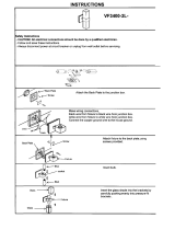
ACCESSORIES CMSHARK
ordered separately) - Fig. 3 and 4
1. Secure Bracket A (2) to Housing with screws provided.
WARNING: Brackets must be mounted at exact location
as shown in Fig. 3.
2. Use appropriate mounting hardware (not supplied) to
secure the Bracket B (2) to mounting surface. Bracket B
distance center to center is 12-19/32” (for 2 feet) and 32”
(for 4 feet).
WARNING: To secure Housing, Bracket B (2) must be
aligned with each other.
3. Hang one side of Bracket A onto Bracket B and tighten
Screw (2) on other side as shown in Fig. 4
Fig. 3
Fig. 4
Fig. 5
Fig. 6
Fig. 7
ACCESSORIES VHOOKSHARK
ordered separately) - Fig. 3 and 5
1. Secure Bracket A (2) to Housing with screws provided.
WARNING: Brackets must be mounted at exact location
as shown in Fig. 3.
2. Loop V-Hooks (2) on Bracket A (2) as shown in Fig. 5.
3. To suspend Housing, connect each V-Hook to two
(2) equal lengths of chain (not supplied) and/ or
appropriate hardware (by others) suitable for mounting
surface. Use chain suitable to support four (4) times the
weight of the xture.
ACCESSORIES JBSHARK
ordered separately) - Fig.4, 6 and 7
1. Secure Bracket A (2) to Housing with screws provided.
WARNING: Brackets must be mounted at exact location
as shown in Fig. 6.
2. Use appropriate mounting hardware (not supplied) to
secure the Junction Box Plate to mounting surface or
junction box. Check that gasket is fully sealed. Use Cord
Grip provided with xture to feed supply wires in xture.
3. Hang one side of each Bracket A onto Junction Box
Plate and tighten Screws (2) on other side as shown in
Fig.4
Bracket A
Housing
Bracket B
Screw (2)
Bracket A (2)
V-Hook (2)
Bracket A (2)
Housing
Junction Box Plate
Distance
NSF COMPLIANCE
To comply with NSF, apply silicone the “X” drive on all plugs
and any unused bracket mounting holes as shown in the g.
2A. Use food grade silicone such as Dow Corning 732.
Fig. 2A
apply silicone
to the holes
apply silicone to
conduit holes

SHARK INSTALLATION INSTRUCTIONS
Thank you for buying RAB lighting xtures. Our goal is to design the best quality products to get the job done right. We’d like to hear your comments.
Call the Marketing Department at 888-RAB-1000 or email: marketing@rabweb.com
TM
Easy Installation & Product Help
Tech Help Line
Call our experts 888 RAB-1000
©2016 RAB LIGHTING Inc.
No
rthvale, New Jersey 07647 USA
rabweb.com
Visit our website for product info
email
Answered promptly sales@rabweb.com
SHARK IN 0517
LIGHT
FIXTURE
(+)LINE BLACK
(-)COMMON WHITE
GROUND GROUND
Fig. 10
Fig. 11
ONOFF WIRING
Universal voltage driver permits operation at 120V thru
277V, 50 or 60 Hz. Units ordered with (/347V) sux are
347V, 50Hz or 60Hz. For Non-Dimming, follow the wiring
directions in Fig. 10.
1. Connect the black xture lead to the LINE supply lead.
2. Connect the white xture lead to the COMMON supply
lead.
3. Connect the GROUND wire from xture to supply
ground.
010V DIMMABLE WIRING
Universal voltage driver permits operation at 120V thru
277V, 50 or 60 Hz. Units ordered with (/347V) sux are
347V, 50Hz or 60Hz. For 0-10V Dimming, follow the wiring
directions in Fig. 11.
1. Connect the black xture lead to the (+) LINE supply lead.
2. Connect the white xture lead to the (-) COMMON
supply lead.
3. Connect the GROUND wire from xture to supply
ground. Do NOT connect the GROUND of the dimming
xture to the output.
4. Connect the purple xture lead to the (V+) DIM lead.
5. Connect the gray xture lead to the (V-) DIM lead.
6. Cap the yellow xture lead, if present. Do NOT connect.
TROUBLESHOOTING
1. Check that the line voltage at the xture is correct. Refer to
wiring directions.
2. Be sure the xture is grounded properly.
Note: These instructions do not cover all details or variations in equipment nor do they provide for every possible situation during installation operation or maintenance.
PATENT - US: pat. D725, 307
ACCESSORIES ANGSHARK
ordered separately) - Fig. 8 and 9
1. Use appropriate mounting hardware (not supplied) to
secure the Corner Bracket (2) to mounting surface as
shown in Fig. 8. Bracket Tabs must face towards each
other. Recommended Corner Bracket distance center to
center is 13-5/16”/ 338.14mm (for 2 feet) and 35-23/32”/
907.26mm (for 4 feet).
2. Secure Snap On Bracket (2) (supplied standard with
Housing) to Corner Bracket (2) with Screws provided as
shown in Fig. 8.
3. Snap Housing on Snap On Brackets (2) as shown in Fig.
2, Page 1. Ensure that Housing is secure to Snap On
Brackets (2) onto the Grooves on Lens as shown in Fig. 1,
Page 1.
Fig. 9
Corner
Bracket (2)
Snap On
Bracket (2)
(supplied
standard w/
Housing)
Housing
Screw
Fig. 8
Bracket Tab
CLEANING & MAINTENANCE
CAUTION: Be sure xture temperature is cool enough
to touch. Do not clean or maintain while xture is
energized.
1. Lens should be washed in a solution of warm water and
any mild, non abrasive household detergent, rinsed with
clean water and wiped dry.
WARNING: Polycarbonate is aected by cleaning
agents or other liquids containing partial solvents
such as low molecular weight aldehydes and
ethers, ketones, esters, aromatic hydrocarbons and
perchlorinated hydrocarbons. In addition, chemical
attack ranging from partial to complete destruction
of polycarbonate occurs in contact with alkalines,
alkali salts, amines and high zone concentrations.
Please go to rclighting.ca for a detailed list of
damaging chemicals.
2. Do not open xture to clean the LED. Do not touch the
LED.

SHARK EMERGENCY BATTERY BACKUP
INSTALLATION INSTRUCTIONS
Thank you for buying RAB lighting xtures. Our goal is to design the best quality products to get the job done right. We’d like to hear your comments.
Call the Marketing Department at 888-RAB-1000 or email: marketing@rabweb.com
TM
SHARK - 4FT
IMPORTANT
READ CAREFULLY BEFORE INSTALLING FIXTURE. RETAIN THESE INSTRUCTIONS FOR FUTURE REFERENCE.
Fixtures must be wired in accordance with the National Electrical Code and all applicable local codes. Proper grounding is required
for safety. THIS PRODUCT MUST BE INSTALLED IN ACCORDANCE WITH THE APPLICABLE INSTALLATION CODE BY A PERSON
FAMILIAR WITH THE CONSTRUCTION AND OPERATION OF THE PRODUCT AND THE HAZARDS INVOLVED.
WARNING: Make certain power is OFF before installing or maintaining xture. No user serviceable parts inside.
SURFACE MOUNTING
The xture is suitable for outdoor applications in wet
locations either ceiling or wall mounted.
1. Use appropriate mounting hardware (not supplied) to
secure the Snap On Brackets (2) to Mounting Surface.
Recommended Snap On Bracket distance center to
center is 37-19/32.”
WARNING: Mount Snap On Brackets (2) farther away
from each other and symmetrical about the center. To
secure Housing, Snap On Brackets (2) must be aligned
with each other.
2. Unlatch the Lens from Housing.
3. Snap out the LED & Heat Sink Assembly. Tether
Cables (2) are provided, if required.
4. Feed supply wires through one of the Conduit Plugs
(5) to make electrical splices. Cord-grips (2) are
provided and can be used based on application.
5. Snap in LED and Heat Sink Assembly and secure Lens
to Housing by Latch. Be careful not to pinch wires.
Check that gasket is fully sealed.
6. Use appropriate UL approved wire connectors as
required by code to complete wiring with supply wires.
Be careful not to pinch wires.
WARNING: To prevent wiring damage or abrasion,
do not expose wiring to edges of sharp objects.
7. Snap Housing on Snap On Brackets (2) as shown
in Fig. 2. Ensure that Housing is secure to Snap On
Brackets (2) and inserted into the Grooves on Lens as
shown in Fig. 1.
8. Use silicone or teon tape on all Conduit Plugs and
on the threads of all conduit entry points. If outdoor
surface is irregular, use caulk to seal any gaps around
Housing.
CAUTION:
• For proper weatherproof function all gaskets must be seated properly and all screws and plugs inserted and
tightened rmly. Apply weatherproof silicone sealant around the edge of the Housing. This is especially important
with an uneven ceiling surface. Silicone all plugs and unused conduit entries.
• ONLY FOR USE WITH CONDUIT
Snap On Bracket (2)
Conduit Plug (5)
Housing
Lens
LED & Heat Sink
Assembly
Tether Cable
Lens
Groove
Latch
Latch
Snap On Bracket
Conduit Plug (5)
Lens
Mounting Surface
Fig. 1
Fig. 2
Test Switch

SHARK EMERGENCY BATTERY BACKUP
INSTALLATION INSTRUCTIONS
Thank you for buying RAB lighting xtures. Our goal is to design the best quality products to get the job done right. We’d like to hear your comments.
Call the Marketing Department at 888-RAB-1000 or email: marketing@rabweb.com
TM
Note: These instructions do not cover all details or variations in
equipment nor do they provide for every possible situation during
installation operation or maintenance.
Easy Installation & Product Help
Tech Help Line
Call our experts 888 RAB-1000
©2015 RAB LIGHTING Inc.
No
rthvale, New Jersey 07647 USA
rabweb.com
Visit our website for product info
email
Answered promptly sales@rabweb.com
SHARK EM IN 1015
PATENT - US: pat. D725, 307
WIRING
CAUTION: THIS IS AN EMERGENCY BATTERY BACKUP
FIXTURE. Voltage could be present in Battery. To prevent
high voltage from being present on output leads, inverter
connector must be open. Do not join inverter connector
until installation is complete and AC power is supplied to
the emergency ballast.
NOTE: Make sure that the necessary branch circuit wiring is
available. An unswitched AC source of power is required. The
emergency ballast must be fed from the same branch circuit
as the AC ballast.
Do not use any supply voltage other than those specied
below.
SHARK4/E2 120V-277V, 50/ 60Hz
1. Connect the UNSWITCHED black xture lead to the HOT
supply lead.
2. Connect red and black lead together, if not using a
switching method.
3. If switching, connect SWITCHED red lead to a switch.
4. Connect the COMMON xture lead to the COMMON
supply lead.
5. For 0-10V Dimming, connect DIM (+) purple lead and DIM
(-) gray lead to 0-10V dimmer. Do not connect the yellow
lead.
5. Connect the GROUND wire from xture to supply ground.
Do NOT connect the GROUND of the dimming xture to
the output.
6. All unused leads must be capped and insulated.
7. After installation is complete, supply AC power to the
emergency ballast and join the inverter connector.
9. At this point, power should be connected to both the
AC ballast and the emergency ballast, and the Charging
Indicator Light on the Test Switch should illuminate
indicating the battery is charging.
10. A short-term discharge test may be conducted after
the emergency ballast has been charging for one hour.
Charge for 24 hours before conducting a long-term
discharge test. Refer to OPERATION.
MAINTENANCE
Although no routine maintenance is required to keep
the emergency ballast functional, it should be checked
periodically to ensure that it is working. The following
schedule is recommended:
1. Visually inspect the charging indicator light monthly. It
should be illuminated.
2. Test the emergency operation of the xture at 30-day
intervals for a minimum of 30 seconds.
3. Conduct a 90-minute discharge test once a year. Fixture
would operate at reduced illumination for a minimum of
90 minutes.
To reduce the risk of electric shock, disconnect both normal and
emergency power supplies and converter connector of the emergency
ballast before servicing. Do not attempt to service the emergency
ballast. The use of accessory equipment may cause an unsafe
condition. Do not use this product for other than intended use.
Refer any servicing indicated by these checks to a Qualied Service
Personnel.
OPERATION
1. When AC power is applied, the charging indicator light is
illuminated, indicating that the battery is being charged.
2. When power fails, the emergency ballast automatically
switches to emergency power (internal battery), operating
at reduced illumination. The emergency ballast supplies
12W of power (measured at nominal battery voltage) at
a maximum rated current of 200mA with a maximum
voltage of 60VDC in emergency mode for a minimum of
90 minutes.
3. When AC power is restored, the emergency ballast
automatically returns to charging mode.
TROUBLESHOOTING
1. Check that the line voltage at xture is correct. Refer to
wiring directions.
2. Is the xture grounded properly?
CLEANING
CAUTION: Be sure xture temperature is cool enough
to touch. Do not clean or maintain while xture is
energized.
1. Lens should be washed in a solution of warm water and
any mild, non abrasive household detergent, rinsed with
clean water and wiped dry.
WARNING: Polycarbonate is aected by cleaning
agents or other liquids containing partial solvents
such as low molecular weight aldehydes and
ethers, ketones, esters, aromatic hydrocarbons and
perchlorinated hydrocarbons. In addition, chemical
attack ranging from partial to complete destruction
of polycarbonate occurs in contact with alkalines,
alkali salts, amines and high zone concentrations.
Please go to rclighting.ca for a detailed list of
damaging chemicals.
2. Do not open xture to clean the LED. Do not touch the
LED.

SHARK EM IN 1015

SHARK 2FT 4FT LENS REPLACEMENT INSTRUCTIONS
TM
Thank you for buying RAB lighting xtures. Our goal is to design the best quality products to get the job done right. We’d like to hear your comments.
Call the Marketing Department at 888-RAB-1000 or email: marketing@rabweb.com
IMPORTANT
READ CAREFULLY BEFORE INSTALLING FIXTURE. RETAIN THESE INSTRUCTIONS FOR FUTURE REFERENCE.
RAB xtures must be wired in accordance with the National Electrical Code and all applicable local codes. Proper grounding
is required for safety. THIS PRODUCT MUST BE INSTALLED IN ACCORDANCE WITH THE APPLICABLE INSTALLATION CODE BY A
PERSON FAMILIAR WITH THE CONSTRUCTION AND OPERATION OF THE PRODUCT AND THE HAZARDS INVOLVED.
WARNING: Make certain power is OFF before installing or maintaining xture.
Housing
Lens
Easy Installation & Product Help
Tech Help Line
Call our experts 888 RAB-1000
©2016 RAB LIGHTING Inc.
Northvale, New Jersey 07647 USA
rabweb.com
Visit our website for product info
email
Answered promptly sales@rabweb.com
Note: These instructions do not cover all details or variations in equipment nor do they provide for every possible situation during installation, operation
or maintenance.
LENS REPLACEMENT- SURFACE
MOUNT
1. To remove the installed Lens, unlatch the Lens from
Housing as shown in gure.
2. Secure replacement Lens to Housing by Latch (6
Latches for 2FT, 10 Latches for 4FT). Check that Gasket is
fully sealed.
LSHARK IN 0216
Latch
Gasket
CLEANING
CAUTION: Be sure xture temperature is cool enough
to touch. Do not clean or maintain while xture is
energized.
1. Lens should be washed in a solution of warm water and
any mild, non abrasive household detergent, rinsed with
clean water and wiped dry.
WARNING: Polycarbonate is aected by cleaning
agents or other liquids containing partial solvents
such as low molecular weight aldehydes and
ethers, ketones, esters, aromatic hydrocarbons and
perchlorinated hydrocarbons. In addition, chemical
attack ranging from partial to complete destruction
of polycarbonate occurs in contact with alkalines,
alkali salts, amines and high zone concentrations.
Please go to rclighting.ca for a detailed list of
damaging chemicals.
2. Do not open xture to clean the LED. Do not touch the
LED.


/