Page is loading ...

PP
PPDD
DDQQ
QQ
300
300
FESTOON SYSTEM
INSTALLATION AND MAINTENANCE INSTRUCTIONS
®
FIXED
TROLLEY
INTERMEDIATE
TROLLEYS*
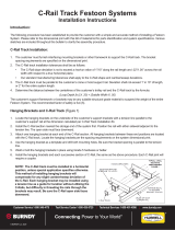
FIGURE 1–TYPICAL INSTALLATION
FIGURE 2–TROLLEY CLEARANCE
TOW
TROLLEY
SHOCK CORD
(optional)
TOW
ROPE
CABLES/
HOSES
FIXED
END I–BEAM TRACK
Sizes S3 x 5.7,
S4 x 7.7, S6 x 12.5.
I–Beam furnished
by customer.
*TRAVEL DISTANCE (ACTIVE TRAVEL) AND
LOOP DEPTH DETERMINE NUMBER OF
INTERMEDIATE TROLLEYS REQUIRED
I–BEAM TRACK INSTALLATION
1. Mount I–beam track to any suitable framework that is strong
enough to support the entire weight of the festoon system (weight
of I–beam, hanging hardware, trolleys and cables or hoses which
will be carried by the festoon). Make sure hardware used for
hanging I–beam will not interfere with free trolley movement.
Refer to Figure 2-Trolley Clearance.
NOTE:
On previously installed track, check all joints and hangers
for clearances shown in Figure 2.
2. Special care should be taken in aligning the I–beam sections to the
crane or hoist support rails. I-beams must be parallel with rails.
ACCEPTABLE SYSTEM TOLERANCES:
HORIZONTAL PLANE: 0.02" per 1.0" across the lower flange width.
RISE/RUN RATIO: 1.0" per 10.0' along track length, maximum of
2.0" for entire SYSTEM LENGTH.
3. Join beams by welding, keeping clearances shown in
Figures 2, & 3. Use beams having the same lower flange
tolerances. Grind welded joints smooth as shown in Figure 3.
STORAGE DISTANCE ACTIVE TRAVEL
LOOP
DEPTH
OBSTRUCTION
UNDER FESTOON 5" MINIMUM
CLEARANCE
INTRODUCTION
The PDQ Festoon System was designed to run on one of three sizes of I-beams: S3 x 5.7, S4 x 7.7, S6 x 12.5. System trolleys must have been
ordered for the size I-beam intended for use or the trolleys will not fit. If your I–beam is not one of those listed above, contact the Gleason Reel
factory or your local Gleason representative. Maximum capacity is 300 lbs. per trolley at 400 fpm.
Each installation includes one fixed trolley, one tow trolley, and a number of intermediate trolleys. Refer to Figure 1-Typical Installation and
Figure 4-Trolley Components and thoroughly familiarize yourself with this product and the terminology used prior to beginning installation.
NOTICE: Safe and proper operation and long life of the PDQ Festoon system depend on proper installation, maintenance,
location and environment. These instructions are intended as a guide but do not cover all possible situations that may
arise. Please refer any questions to Gleason Reel or its authorized representative or distributor.
I–BEAM
SIDE CLEARANCE
BOTH SIDES
DIM “A”
FLANGED
WHEELS
INTERMEDIATE
OR
TOW TROLLEY
ANTI–LIFT
WHEEL
MAX. HANGER
OBSTRUCTION–DIM “B”
NO
FASTENERS
ALLOWED
FIG 3–WELDED JOINT
GRIND THESE
SURFACES SMOOTH
BEAM
SIZE DIM
“A” DIM
“B”
3"
4"
6"
0.25"
0.38"
0.5"
0.5
1.25"
3.25"
Gleason Reel Corp.
P.O. Box 26, 600 S. Clark St.
Mayville, Wisconsin 53050-0026
Phone 920/387-4120
FAX 920/387-4189
PRINTED IN U.S.A. © COPYRIGHT GLEASON REEL CORP. 1998 BULLETIN 039770.b
1
1
24 4
5
5
5
5
6
7
8
8
9
24
9
10
24
11
5
12
5
13 14
15
16
17
18
19
FIXED TROLLEY
NOTE:
Always include trolley type, capacity,
size I-beam, and size saddle when
ordering parts or kits.
®
HUBBELL
®
A Hubbell Company
9" dia. SADDLE
6" dia. SADDLE
NOTE:
Primary illustration shows bumpers
and spacers for 12" diameter sad-
dle. Bumpers for 6" and 9" saddles
shown in boxes.

D. Mount fixed trolley to I-beam using hex head bolt, flat
washers, spacers and lock nut, supplied. See Figure 7.
6. Remove temporary restraints securing trolleys in storage
position (Step 3).
7. Roll all wheeled trolleys along entire length of track. Check
for binding or interference from hanging or joining hardware or
weld bead. Fix areas of concern.
8. Set clearances for TOW trolley. NOTE: Tow arm is
supplied by customer and must work to minimum clearances
of rectangular tube. Check tow arm movement throughout
total system travel to insure it does not pull out of
rectangular tube in tow trolley and that no upward or downward
forces are transmitted to tow trolley. See Fig. 9.
E. Weld or bolt a thrust bar to I-beam directly behind the
fixed trolley to absorb impact forces. See Figure 8.
FIGURE 4–TROLLEY COMPONENTS FIGURE 7–SECURING FIXED TROLLEY
FIGURE 8–FIXED TROLLEY THRUST BAR
FIGURE 5–LOCATING FIXED TROLLEY HOLES
2.25" dia. WHEELS
CARRIAGE
PLATE
RUBBER
BUMPERS
INTERMEDIATE TROLLEY
SHOWN
ANTI–LIFT
WHEELS
ONE PIECE
RETAINER
ONE PIECE
CLAMP PAD
SADDLE
TROLLEY INSTALLATION
There are three types of trolleys: Fixed, Intermediate, and Tow. The FIXED trolley is the first trolley on the storage end of the system. It is
stationary, bolted to the track, and acts as the “bumper” to stop the trolleys when they are moved into storage. See Figure 1–Typical Installation.
INTERMEDIATE trolleys carry the cable or hose. Number and spacing of intermediate trolleys is determined by length of cable/hose and
loop depth. The TOW trolley is last in the string and is attached to the machine (crane, machine tool, etc.) serviced by the festoon system.
1. Check to make sure all trolleys are sized for I-beam installed
previously. No width adjustment is required or possible. If
trolleys do not fit I-beam, consult factory or Gleason representative.
2. Slide all trolleys onto I-beam track in order shown in Figure 1.
NOTE: Fixed trolley will rest on cut-outs in carriage plates.
3. Temporarily position trolleys as they will be stored. There should
be 1/8" between bumpers. Tow trolley must be at or beyond
limits of machine movement.
4. Fasten FIXED TROLLEY to I-beam.
A. Temporarily slide fixed trolley out of the way.
B. Mark vertical location of mounting holes on beam web,
1.2" above bottom of I-beam. One method of doing this
is by using two squares as shown in Figure 5.
1.2" ABOVE
BOTTOM OF
BEAM
SQUARES
MARK TWO PLACES
5.5" APART
C. Mark horizontal location of holes. Holes must be 5.5"
apart and in final location for fixed trolley. Drill two
0.562" dia. holes thru web. See Figure 6.
5.5"
0.562" dia.
HOLES THRU
1.2"
WEB
FIGURE 6–BEAM DRILLING FIGURE 9–TOW ARM CLEARANCE
HEX HD. CAP SCREW
Length varies with
I-beam size
LOCK NUT
Torque to 60 ft-lbs
lubricated FLAT WASHER
FLAT WASHER
FIXED TROLLEY
SPACERS
FIXED TROLLEY
THRUST BAR
I-BEAM TRACK
0.5" min. clearance
0.5"
4.6"
I-BEAM
TRACK
0.10" min.
clearance
1.0" min.
beyond
tow tube 1.25"
TOW
ARM
TOW
TROLLEY
TOW TUBE
ON
TROLLEY
2.1"
1
1
2
2
14
2
2
3
3
3
4
4
5
5
5
512
11
5
5
6
7
8
8
8
10
15
16
17
18
23
22
20
22
21
19
TOW TROLLEY
NOTE:
Always include trolley type, capacity,
size I-beam, and size saddle when
ordering parts or kits.
9" & 12" dia.
SADDLE
6" dia. SADDLE
NOTE:
Primary illustration shows bumpers for
9" and 12" diameter saddle. Bumpers
for 6" saddles shown in boxes.
R.H. Carriage Plate
L.H. Carriage Plate

Cable Layout when General Arrangement Drawing
is provided.
1. Remove all twist from round cable.
2. On cable, mark length required between TOW trolley and
termination junction.
3. Mark CABLE LENGTH LOOPS per General Arrangement
Drawing. Remaining cable is for hookup from FIXED
trolley to termination point.
4. Hang cable. All marks on cable must align with tops of
saddles. See Figure 19. Arrange multiple cables per General
Arrangement Drawing.
Cable Loop Adjustments (For two or more layers of flat cable)
1. Starting at the Tow Trolley, loosen cable clamp on FIRST
intermediate trolley.
2. Without shifting the lowest layer of cable, shorten each successive
layer of cables upward in the loop to create a space of
approximately 1/4". See Figure 20.
3. Reclamp cables and make certain that the smallest cable cannot
shift or be pulled through by hand.
4. Adjust each cable loop in the same manner as described in steps
2 & 3. Continue these procedures, working toward the
Fixed Trolley.
5. Cut the cables to the correct length at the Fixed Trolley
termination junction.
4. Hang cable. All marks on cable must align with tops of saddles.
See Figure 19. Arrange multiple cables using guidelines above.
Cable Layout when no General Arrangement Drawing
is provided.
1. On cable, mark length required between TOW trolley and
termination junction.
2. Mark length required from FIXED trolley to termination point.
3. Divide remaining cable into equal lengths per number of CABLE
LOOPS and mark each length.
5. Complete cable termination connections after loops have been
adjusted and loop clamps installed. Avoid connections or splices
at any loop between TOW trolley and FIXED trolley.
6. After cable loop(s) is aligned, clamp cables in place using cable
clamps on the saddle. Cable clamps should be tightened so that
the smallest cable cannot be pulled through by hand.
7. Install CABLE LOOP CLAMPS at bottom of each single layered
loop. Tighten. NOTE: Flat cable may be “stacked” (see CABLE
GUIDELINES, above). If cable is stacked, adjust loops as shown
in CABLE LOOPADJUSTMENTS section, right.
5. Complete cable termination connections after loops have been
adjusted and loop clamps installed. Avoid connections or splices
at any loop between TOW trolley and FIXED trolley.
6. After cable loop(s) is aligned, clamp cables in place using cable
clamps on the saddle. Cable clamps should be tightened so that the
smallest cable cannot be pulled through by hand.
7. Install CABLE LOOP CLAMPS at bottom of each loop. Tighten.
NOTE: Flat cable may be “stacked” (see CABLE
GUIDELINES, above). If cable is stacked:
A. If you received one cable clamp per loop, arrange
cables as indicated above.
B. If you received two cable clamps per loop, adjust
loops as shown in CABLE LOOPADJUSTMENTS
section, below.
CABLE INSTALLATION
Proper cable installation is the key to a successful festoon system. Refer to the guidelines below while following the cable installation procedure.
CABLE GUIDELINES
Bending Cables
It is best to follow the rule that “BIG BENDS ARE BEST” for
good service and long life. Cable manufacturers vary in apply-
ing a multiplier and we offer the following guide as typical.
Gleason uses the chart below.
Cable O.D. Variations
Variations should be kept to a minimum. Clamping is best
accomplished when all cables are same O.D. or close (Figure
10). Wide deviation (Figure 11) makes clamping difficult and
cable may not remain in saddle.
CABLE
O.D. MINIMUM
RADIUS MINIMUM
SADDLE DIA.
Under 0.3 in.
Under 0.5 in.
Under 0.8 in.
3 x O.D.
4 x O.D.
5 x O.D.
6 x O.D.
8 x O.D.
10 x O.D.
LARGE BEST SMALL POOR
C
LC
L
FIGURE 10–BEST FIGURE 11–POOR
Balance in Loading Cable
This is important for smooth running, long wheel
bearing life and alignment of components. It is best
to distribute the cable evenly, with the heaviest cables
near the center.
C
L
C
L
FIGURE 12–BEST FIGURE 13–POOR
Flat Cable Stacking
A. Secure clamping
EXTREMELY IMPORTANT: At least 50% of cable
surface must be under clamp pressure.
B. Height consideration
Flat cable stacking best when
width is 3–4 times height, as in
Figures 14 & 15 above. High
stacking can work as long as
equal pressure is applied to all
cables. See Figure 17.
C. Configuration
BIG CABLE ON TOP provides
maximum bending radius,
improves heat dissipation and
takes pulling force when tow
cables are not used. See Fig. 18.
FIGURE 14 FIGURE 15 FIGURE 16
BEST GOOD POOR
100% clamping 50% clamping
FIGURE 17
OK
FIGURE 18
BEST
FIGURE 19–ALIGNING CABLE MARKS
INTERMEDIATE
TROLLEY
CABLE
SADDLE
MARK ON
CABLE
CABLE
NUMBER OF = NUMBER OF +1
CABLE LOOPS INTERMEDIATE TROLLEYS
1
1
2
2
2
2
3
3
3
4
5
5
5
5
5
5
6
7
8
8
9
9
9
9
10
10
11
12
13 14
15
16
17
18
19
INTERMEDIATE TROLLEY
NOTE:
Always include trolley type, capacity,
size I-beam, and size saddle when
ordering parts or kits.
9" dia. SADDLE
6" dia. SADDLE
NOTE:
Primary illustration shows bumpers
and spacers for 12" diameter sad-
dle. Bumpers for 6" and 9" saddles
shown in boxes.

PP
PPDD
DDQQ
QQ300
300
FESTOON SYSTEM
ILLUSTRATED PARTS LIST
This illustrated parts list was designed to serve both as a source for repair parts and as a guide for repair and replacement. For more details see
appropriate section elsewhere in this INSTALLATION AND MAINTENANCE instruction booklet. Note that many items are available only as
repair kits. These kits usually include all related hardware as well as the primary part. For example, kit number 039487 contains the wheel and
also the washer and lock nut required to affix the wheel to the trolley. Common hardware not contained in a kit does not include a part number
and may be purchased locally.
ITEM NO. PART/KIT NO. DESCRIPTION QTY. EA. QTY. EA. QTY. EA.
INTERMED. TOW FIXED
TROLLEY TROLLEY TROLLEY
1 039750 Carriage Plate (6"dia. saddle) 2 2 2
(9" dia. saddle) 2 – 2
(12” dia. saddle) 2 – 2
1 04152601 L.H. Carriage Plate (9" dia. saddle) – 1 –
1 04152602 R.H. Carriage Plate (9" dia. saddle) – 1 –
1 04152401 L.H. Carriage Plate (12" dia. saddle) – 1 –
1 04152402 R.H. Carriage Plate (12" dia. saddle) – 1 –
2 039769 Wheel Kit–PDQ 300 4*4*–
Includes 2.25" dia. wheel, washer and lock nut.
3 039761 Anti–lift Wheel Kit (3" I-beam) 2* 2* –
Includes wheel, flat washer and lock nut.
3 039762 Anti–lift Wheel Kit (4" I-beam) 2* 2* –
3 039763 Anti–lift Wheel Kit (6" I-beam) 2* 2* –
4 03973901 Spacer–3" I-beam 4*4*4*
4 03973902 Spacer–4" I-beam 4*4*4*
4 03973903 Spacer–6" I-beam 4*4*4*
5 Flat Washer, 1/2" 12 10 10
6 Lock Nut, 1/2-13 2 2 2
7 Hex Hd. Cap Screw, 1/2-13 x 2.25" lg. (3" I-beam) 2*2*2*
7 Hex Hd. Cap Screw, 1/2-13 x 2.50" lg. (4" I-beam) 2*2*
2*7 Hex Hd. Cap Screw, 1/2-13 x 3.25" lg. (6" I-beam) 2*2*2*
8 039764 Bumper Kit (6" dia. saddle) 4*4*4*
Includes bumper, mounting screw, washer and nut..
8 039489 Bumper Kit (9" & 12" dia. saddle) 4*2*2*
Includes bumper, flat washer, hex lock nut.
9 039765 Bumper Extension Kit (12" saddle) 4*–2*
Includes spacer and hardware only. Bumper not included.
10 017492 Bumper Only (9" &12" saddles only) 4** 2** 2**
11 Lock Nut/Nylon Insert, 1/2-13 2 1 1
12 Hex Hd. Cap Screw, 1/2-13 x 2.0 (3" I-beam) 2*1*1*
12 Hex Hd. Cap Screw, 1/2-13 x 2.50 (4" I-beam) 2*1*1*
12 Hex Hd. Cap Screw, 1/2-13 x 3.25 (6" I-beam) 2*1*1*
13 Tow Rope (Call factory with length) 1 – 1
14 Shock Cord (Call factory with length) 2 – 2
15 03974901 Saddle Weldment, 6.0" dia. x 7.50" wide
15 03974902 Saddle Weldment, 6.0" dia. x 9.50" wide
15 03974903 Saddle Weldment, 6.0" dia. x 11.50" wide One saddle needed per trolley.
15 03974801 Saddle Weldment, 9.0" dia. x 7.50" wide Be sure to order correct size.
15 03974802 Saddle Weldment, 9.0" dia. x 9.50" wide
15 03974803 Saddle Weldment, 9.0" dia. x 11.50" wide
15 03974701 Saddle Weldment, 12.0" dia. x 7.50" wide
15 03974702 Saddle Weldment, 12.0" dia. x 9.50" wide
15 03974703 Saddle Weldment, 12.0" dia. x 11.50" wide
16 01904813 Retainer, 7.5" wide saddle 1*1*1*
16 01904814 Retainer, 9.5" wide saddle 1*1*1*
16 01904815 Retainer, 11.5" wide saddle 1*1*1*
17 03556013 Clamp Pad, 7.5" wide saddle 1*1*1*
17 03556014 Clamp Pad, 9.5" wide saddle 1*1*1*
17 03556015 Clamp Pad, 11.5" wide saddle 1*1*1*
18 01875601 Hex Hd, Cap Screw, 1/2-13 x 5" lg. (full thread) 6" dia. Saddle 2*2*2*
18 01875605 Hex Hd, Cap Screw, 1/2-13 x 6" lg. (full thread) 9"/12" Saddle 2*2*2*
19 Hex Nut, 1/2-13 2 2 2
20 039756 Tow Arm Weldment – 1 –
21 Hex Hd. Cap Screw, 3/16"-18 x 1" lg. – 2 –
22 Flat Washer, 3/16 – 4 –
23 ESNA Lock Nut, 3/6-18 – 2 –
24 039766 Fixing Spacer Kit (3" I-beam) – – 2*
24 039767 Fixing Spacer Kit (4" I-beam) – – 2*
24 039768 Fixing Spacer Kit (6" I-beam) – – 2*
*Be sure to state capacity, I-beam and saddle size on order.
6. Install cable loop clamps (two per loop).
A. Locate cable clamps approximately half way down each
side of loop.
B. Stagger clamps as shown in Figure 20 to prevent them from
colliding with each other during system operation.
FIGURE 20–CABLE LOOP ADJUSTMENT
FIGURE 21–TOW ROPE INSTALLATION
HALF OF
CABLE LOOP
CABLE
LOOP
DEPTH
1/4" SPACE
BETWEEN
CABLES
1/4" SPACE
BETWEEN
CABLES
STAGGER
CLAMPS
INSTALLING TOW ROPES
Tow ropes “pull” the festoon system along the track, minimizing wear to
and prolonging the life of electrical cables or hoses being carried.
Without tow ropes, the electrical cables are required to act as tension
members which can lead to separated conductors. On multiple cable
applications it is virtually impossible to adjust a festoon system so that all
cables are exactly the same length. Thus all force is directed to the
shortest cable, further compounding the problem. Tow ropes are slightly
shorter than the cables in each loop and no strain is put on the electrical
cables or hoses themselves. See Figure 1–Typical Installation.
1. Mount tow ropes with fasteners supplied. See Figure 21.
INSTALLING SHOCK CORDS
(when required)
Shock Cords are slightly shorter than tow cables and are used in
pairs...two between each trolley. Spring loaded, their function is just as
their name implies; they act as shock absorbers when the festoon trolleys
are beginning to move, limiting undue stress on the tow ropes.
1. Mount two shock cords between each pair of trolleys as shown
in Figure 22.
TESTING
1. With tow arm not attached to tow trolley, spread each set of
trolleys and check to make sure tow rope gets tight before
electrical cables or hoses. Adjust length of cable or hose loop,
as required.
2. Spread each set of trolleys and check to make sure shock cords
are stretched before tow rope gets tight.
3. Connect tow arm to tow trolley and slowly operate festoon system
throughout the total travel. Check for “smooth rolling wheels”,
misaligned joints, hanging or joining hardware interference, and
interference of cable loops with operating area.
4. With festoon trolleys in STORAGE POSITION, check to see that
intermediate trolleys can move back and forth slightly. They must
not be packed “tight” when tow arm is at end of travel.
5. With festoon system FULLY EXTENDED, check each loop to
see that cables are suspended uniformly between trolleys and that
cable load is balanced in saddle.
6. Correct all problems before routine operation of crane or hoist.
MAINTENANCE
1. During normal equipment inspection, perform the following
checks and maintenance:
A. Check for wear on trolley wheels and anti-lift rollers. Wheel
and anti-lift roller bearings are sealed and do not require
routine maintenance.
B. Check for loose fasteners and nuts, especially the bolts
affixing the fixed trolley to the I-beam. Tighten if required.
C. Check for wear or fractured walls on the rectangular tube on
the tow trolley. Repair or replace as necessary. If undue wear
persists, check alignment of tow arm throughout entire travel.
Refer to TROLLEY INSTALLATION, Step 8.
D. Check condition of bumpers, tow ropes and shock cords.
Replace as required.
E. Check for damaged cable and the tightness of cable
and loop clamps.
TOW ROPES
LOCK NUT
DO NOT TORQUE
FLAT
WASHERS
TROLLEY
TOW
ROPE
HEX HD.
CAP SCREW
FIGURE 22–SHOCK CORD INSTALLATION
TOW
ROPES
SHOCK
CORD SHOCK
CORD
SHOCK CORDS
HOOK INTO
HOLES IN
TROLLEY
TROLLEY

Cable Layout when General Arrangement Drawing
is provided.
1. Remove all twist from round cable.
2. On cable, mark length required between TOW trolley and
termination junction.
3. Mark CABLE LENGTH LOOPS per General Arrangement
Drawing. Remaining cable is for hookup from FIXED
trolley to termination point.
4. Hang cable. All marks on cable must align with tops of
saddles. See Figure 19. Arrange multiple cables per General
Arrangement Drawing.
Cable Loop Adjustments (For two or more layers of flat cable)
1. Starting at the Tow Trolley, loosen cable clamp on FIRST
intermediate trolley.
2. Without shifting the lowest layer of cable, shorten each successive
layer of cables upward in the loop to create a space of
approximately 1/4". See Figure 20.
3. Reclamp cables and make certain that the smallest cable cannot
shift or be pulled through by hand.
4. Adjust each cable loop in the same manner as described in steps
2 & 3. Continue these procedures, working toward the
Fixed Trolley.
5. Cut the cables to the correct length at the Fixed Trolley
termination junction.
4. Hang cable. All marks on cable must align with tops of saddles.
See Figure 19. Arrange multiple cables using guidelines above.
Cable Layout when no General Arrangement Drawing
is provided.
1. On cable, mark length required between TOW trolley and
termination junction.
2. Mark length required from FIXED trolley to termination point.
3. Divide remaining cable into equal lengths per number of CABLE
LOOPS and mark each length.
5. Complete cable termination connections after loops have been
adjusted and loop clamps installed. Avoid connections or splices
at any loop between TOW trolley and FIXED trolley.
6. After cable loop(s) is aligned, clamp cables in place using cable
clamps on the saddle. Cable clamps should be tightened so that
the smallest cable cannot be pulled through by hand.
7. Install CABLE LOOP CLAMPS at bottom of each single layered
loop. Tighten. NOTE: Flat cable may be “stacked” (see CABLE
GUIDELINES, above). If cable is stacked, adjust loops as shown
in CABLE LOOPADJUSTMENTS section, right.
5. Complete cable termination connections after loops have been
adjusted and loop clamps installed. Avoid connections or splices
at any loop between TOW trolley and FIXED trolley.
6. After cable loop(s) is aligned, clamp cables in place using cable
clamps on the saddle. Cable clamps should be tightened so that the
smallest cable cannot be pulled through by hand.
7. Install CABLE LOOP CLAMPS at bottom of each loop. Tighten.
NOTE: Flat cable may be “stacked” (see CABLE
GUIDELINES, above). If cable is stacked:
A. If you received one cable clamp per loop, arrange
cables as indicated above.
B. If you received two cable clamps per loop, adjust
loops as shown in CABLE LOOPADJUSTMENTS
section, below.
CABLE INSTALLATION
Proper cable installation is the key to a successful festoon system. Refer to the guidelines below while following the cable installation procedure.
CABLE GUIDELINES
Bending Cables
It is best to follow the rule that “BIG BENDS ARE BEST” for
good service and long life. Cable manufacturers vary in apply-
ing a multiplier and we offer the following guide as typical.
Gleason uses the chart below.
Cable O.D. Variations
Variations should be kept to a minimum. Clamping is best
accomplished when all cables are same O.D. or close (Figure
10). Wide deviation (Figure 11) makes clamping difficult and
cable may not remain in saddle.
CABLE
O.D. MINIMUM
RADIUS MINIMUM
SADDLE DIA.
Under 0.3 in.
Under 0.5 in.
Under 0.8 in.
3 x O.D.
4 x O.D.
5 x O.D.
6 x O.D.
8 x O.D.
10 x O.D.
LARGE BEST SMALL POOR
C
LC
L
FIGURE 10–BEST FIGURE 11–POOR
Balance in Loading Cable
This is important for smooth running, long wheel
bearing life and alignment of components. It is best
to distribute the cable evenly, with the heaviest cables
near the center.
C
L
C
L
FIGURE 12–BEST FIGURE 13–POOR
Flat Cable Stacking
A. Secure clamping
EXTREMELY IMPORTANT: At least 50% of cable
surface must be under clamp pressure.
B. Height consideration
Flat cable stacking best when
width is 3–4 times height, as in
Figures 14 & 15 above. High
stacking can work as long as
equal pressure is applied to all
cables. See Figure 17.
C. Configuration
BIG CABLE ON TOP provides
maximum bending radius,
improves heat dissipation and
takes pulling force when tow
cables are not used. See Fig. 18.
FIGURE 14 FIGURE 15 FIGURE 16
BEST GOOD POOR
100% clamping 50% clamping
FIGURE 17
OK
FIGURE 18
BEST
FIGURE 19–ALIGNING CABLE MARKS
INTERMEDIATE
TROLLEY
CABLE
SADDLE
MARK ON
CABLE
CABLE
NUMBER OF = NUMBER OF +1
CABLE LOOPS INTERMEDIATE TROLLEYS
1
1
2
2
2
2
3
3
3
4
5
5
5
5
5
5
6
7
8
8
9
9
9
9
10
10
11
12
13 14
15
16
17
18
19
INTERMEDIATE TROLLEY
NOTE:
Always include trolley type, capacity,
size I-beam, and size saddle when
ordering parts or kits.
9" dia. SADDLE
6" dia. SADDLE
NOTE:
Primary illustration shows bumpers
and spacers for 12" diameter sad-
dle. Bumpers for 6" and 9" saddles
shown in boxes.

D. Mount fixed trolley to I-beam using hex head bolt, flat
washers, spacers and lock nut, supplied. See Figure 7.
6. Remove temporary restraints securing trolleys in storage
position (Step 3).
7. Roll all wheeled trolleys along entire length of track. Check
for binding or interference from hanging or joining hardware or
weld bead. Fix areas of concern.
8. Set clearances for TOW trolley. NOTE: Tow arm is
supplied by customer and must work to minimum clearances
of rectangular tube. Check tow arm movement throughout
total system travel to insure it does not pull out of
rectangular tube in tow trolley and that no upward or downward
forces are transmitted to tow trolley. See Fig. 9.
E. Weld or bolt a thrust bar to I-beam directly behind the
fixed trolley to absorb impact forces. See Figure 8.
FIGURE 4–TROLLEY COMPONENTS FIGURE 7–SECURING FIXED TROLLEY
FIGURE 8–FIXED TROLLEY THRUST BAR
FIGURE 5–LOCATING FIXED TROLLEY HOLES
2.25" dia. WHEELS
CARRIAGE
PLATE
RUBBER
BUMPERS
INTERMEDIATE TROLLEY
SHOWN
ANTI–LIFT
WHEELS
ONE PIECE
RETAINER
ONE PIECE
CLAMP PAD
SADDLE
TROLLEY INSTALLATION
There are three types of trolleys: Fixed, Intermediate, and Tow. The FIXED trolley is the first trolley on the storage end of the system. It is
stationary, bolted to the track, and acts as the “bumper” to stop the trolleys when they are moved into storage. See Figure 1–Typical Installation.
INTERMEDIATE trolleys carry the cable or hose. Number and spacing of intermediate trolleys is determined by length of cable/hose and
loop depth. The TOW trolley is last in the string and is attached to the machine (crane, machine tool, etc.) serviced by the festoon system.
1. Check to make sure all trolleys are sized for I-beam installed
previously. No width adjustment is required or possible. If
trolleys do not fit I-beam, consult factory or Gleason representative.
2. Slide all trolleys onto I-beam track in order shown in Figure 1.
NOTE: Fixed trolley will rest on cut-outs in carriage plates.
3. Temporarily position trolleys as they will be stored. There should
be 1/8" between bumpers. Tow trolley must be at or beyond
limits of machine movement.
4. Fasten FIXED TROLLEY to I-beam.
A. Temporarily slide fixed trolley out of the way.
B. Mark vertical location of mounting holes on beam web,
1.2" above bottom of I-beam. One method of doing this
is by using two squares as shown in Figure 5.
1.2" ABOVE
BOTTOM OF
BEAM
SQUARES
MARK TWO PLACES
5.5" APART
C. Mark horizontal location of holes. Holes must be 5.5"
apart and in final location for fixed trolley. Drill two
0.562" dia. holes thru web. See Figure 6.
5.5"
0.562" dia.
HOLES THRU
1.2"
WEB
FIGURE 6–BEAM DRILLING FIGURE 9–TOW ARM CLEARANCE
HEX HD. CAP SCREW
Length varies with
I-beam size
LOCK NUT
Torque to 60 ft-lbs
lubricated FLAT WASHER
FLAT WASHER
FIXED TROLLEY
SPACERS
FIXED TROLLEY
THRUST BAR
I-BEAM TRACK
0.5" min. clearance
0.5"
4.6"
I-BEAM
TRACK
0.10" min.
clearance
1.0" min.
beyond
tow tube 1.25"
TOW
ARM
TOW
TROLLEY
TOW TUBE
ON
TROLLEY
2.1"
1
1
2
2
14
2
2
3
3
3
4
4
5
5
5
512
11
5
5
6
7
8
8
8
10
15
16
17
18
23
22
20
22
21
19
TOW TROLLEY
NOTE:
Always include trolley type, capacity,
size I-beam, and size saddle when
ordering parts or kits.
9" & 12" dia.
SADDLE
6" dia. SADDLE
NOTE:
Primary illustration shows bumpers for
9" and 12" diameter saddle. Bumpers
for 6" saddles shown in boxes.
R.H. Carriage Plate
L.H. Carriage Plate

PP
PPDD
DDQQ
QQ
300
300
FESTOON SYSTEM
INSTALLATION AND MAINTENANCE INSTRUCTIONS
®
FIXED
TROLLEY
INTERMEDIATE
TROLLEYS*
FIGURE 1–TYPICAL INSTALLATION
FIGURE 2–TROLLEY CLEARANCE
TOW
TROLLEY
SHOCK CORD
(optional)
TOW
ROPE
CABLES/
HOSES
FIXED
END I–BEAM TRACK
Sizes S3 x 5.7,
S4 x 7.7, S6 x 12.5.
I–Beam furnished
by customer.
*TRAVEL DISTANCE (ACTIVE TRAVEL) AND
LOOP DEPTH DETERMINE NUMBER OF
INTERMEDIATE TROLLEYS REQUIRED
I–BEAM TRACK INSTALLATION
1. Mount I–beam track to any suitable framework that is strong
enough to support the entire weight of the festoon system (weight
of I–beam, hanging hardware, trolleys and cables or hoses which
will be carried by the festoon). Make sure hardware used for
hanging I–beam will not interfere with free trolley movement.
Refer to Figure 2-Trolley Clearance.
NOTE:
On previously installed track, check all joints and hangers
for clearances shown in Figure 2.
2. Special care should be taken in aligning the I–beam sections to the
crane or hoist support rails. I-beams must be parallel with rails.
ACCEPTABLE SYSTEM TOLERANCES:
HORIZONTAL PLANE: 0.02" per 1.0" across the lower flange width.
RISE/RUN RATIO: 1.0" per 10.0' along track length, maximum of
2.0" for entire SYSTEM LENGTH.
3. Join beams by welding, keeping clearances shown in
Figures 2, & 3. Use beams having the same lower flange
tolerances. Grind welded joints smooth as shown in Figure 3.
STORAGE DISTANCE ACTIVE TRAVEL
LOOP
DEPTH
OBSTRUCTION
UNDER FESTOON 5" MINIMUM
CLEARANCE
INTRODUCTION
The PDQ Festoon System was designed to run on one of three sizes of I-beams: S3 x 5.7, S4 x 7.7, S6 x 12.5. System trolleys must have been
ordered for the size I-beam intended for use or the trolleys will not fit. If your I–beam is not one of those listed above, contact the Gleason Reel
factory or your local Gleason representative. Maximum capacity is 300 lbs. per trolley at 400 fpm.
Each installation includes one fixed trolley, one tow trolley, and a number of intermediate trolleys. Refer to Figure 1-Typical Installation and
Figure 4-Trolley Components and thoroughly familiarize yourself with this product and the terminology used prior to beginning installation.
NOTICE: Safe and proper operation and long life of the PDQ Festoon system depend on proper installation, maintenance,
location and environment. These instructions are intended as a guide but do not cover all possible situations that may
arise. Please refer any questions to Gleason Reel or its authorized representative or distributor.
I–BEAM
SIDE CLEARANCE
BOTH SIDES
DIM “A”
FLANGED
WHEELS
INTERMEDIATE
OR
TOW TROLLEY
ANTI–LIFT
WHEEL
MAX. HANGER
OBSTRUCTION–DIM “B”
NO
FASTENERS
ALLOWED
FIG 3–WELDED JOINT
GRIND THESE
SURFACES SMOOTH
BEAM
SIZE DIM
“A” DIM
“B”
3"
4"
6"
0.25"
0.38"
0.5"
0.5
1.25"
3.25"
Gleason Reel Corp.
600 S. Clark St.
Mayville, Wisconsin 53050-0026
Phone 920/387-4120
FAX 920/387-4189
PRINTED IN U.S.A. © COPYRIGHT GLEASON REEL CORP. 1998 BULLETIN 039770.b
1
1
24 4
5
5
5
5
6
7
8
8
9
24
9
10
24
11
5
12
5
13 14
15
16
17
18
19
FIXED TROLLEY
NOTE:
Always include trolley type, capacity,
size I-beam, and size saddle when
ordering parts or kits.
®
HUBBELL
®
A Hubbell Company
9" dia. SADDLE
6" dia. SADDLE
NOTE:
Primary illustration shows bumpers
and spacers for 12" diameter sad-
dle. Bumpers for 6" and 9" saddles
shown in boxes.
/