Page is loading ...

MAINTENANCE
1. During normal equipment inspection, perform the following checks and maintenance:
A. Check for wear on trolley wheels and anti-lift rollers. Wheel and anti-lift roller bearings
on trolley are sealed and do not require routine maintenance.
B. Check for loose fasteners and nuts, especially the bolt affixing the I-beam to the top
of the vertical column. Tighten if required.
C. Check festoon trolley cable for damage and tightness. Replace or tighten as required.
D. Check loop clamps on festoon trolleys for tightness. Tighten if required.
E. Check rollers on
Lock n’ Roll
Festoon trolleys for wear. Replace if necessary.
ADDING OR REPLACING TOOL TROLLEY
NOTE: Jib is supplied with one tool trol-
ley. If a second one is desired, or if trolley
needs replacing, follow steps below:
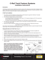
1. Remove end stop and festoon cable
anchor bracket at end of boom (Fig. 5).
2. Slide new trolley in place on
I-beam.
3. Replace end stop and festoon anchor
bracket removed in step one. Securely
tighten.
4. Check festoon trolley cable for tight-
ness. Tighten as required.
PARTS LIST
Tool Trolley . . . . . . . . . . . . . . . . . . . . . . . . . . . . . . . .W6S-BT
Lock ‘n Roll Festoon Trolley . . . . . . . . . . . . . . . . . . . .FRT-05
Slip Ring including enclosure . . . . . . . . . . . . . . . . . . .SB360-430-Y
Stand-off Kit . . . . . . . . . . . . . . . . . . . . . . . . . . . . . . . .SB360-SOK
Full Rotation Stop Kit . . . . . . . . . . . . . . . . . . . . . . . . .W6S-SK
The 300 lb. Jib is designed for use with electrically powered or other low capacity hoists and
balancers or electric tools. Total capacity of the jib is 300 lbs. (135kg) including weight of
hoists, balancers and other equipment. The 10' (3m) boom features 360Orotation, an
enclosed slip ring and pre-wired junction box for easy electrical hook up, a high
capacity trolley with bumpers, and wire-rope mounted festoon trolleys to support
cable supplying electrical power to hoist or electric tool.
Installation consists of three basic operations:
I. Attaching vertical column to suitable anchor bolts
(suggested foundation is detailed on Page 2).
II. Affixing boom to top of vertical column.
III. Making electric connections and
adjusting festoon trolleys.
MOUNTING VERTICAL COLUMN
CAUTION
Install only with bolts properly anchored into
reinforced concrete. Suggested foundation is detailed
on page 2. Improper anchoring could result in
serious personal injury.
1. Become thoroughly familiar with general arrangement and terms (Fig 1).
2. Select area in which jib is to be installed. If full 360Oswing is desired, there must be no
obstructions within a 20' (6m) diameter x 12' (2.4m) high area.
3. Determine anchoring to be used. A full foundation, as detailed on
following page, is recommended. Five 3/4" anchor bolts, extending
3"–4" (76-102mm) above concrete floor surface, must be equally
spaced on 14" (356mm)dia. circle (Fig. 2).
4. Erect, level, shim & grout, and bolt down column. Allow to thor-
oughly set. NOTE: Column must be plumb.
INSTALLATION INSTRUCTIONS
300 lb. Capacity Tool Jib with Electric Slip Rings
WIRE ROPE
FESTOON
TROLLEYS
SLIP RING IN
ENCLOSURE
3/4" NPT
LINE
ENTRANCE
PRE-WIRED
FLEX
CONDUIT &
JUNCTION
BOX
ACCESS
COVER
-one of two-
VERTICAL
SUPPORT
COLUMN
I-BEAM
BOOM
MOUNTING
BASE
TOOL
TROLLEY
Fig. 1
Fig. 2
14" (356)
dia.
BOLT
CIRCLE
16" (406)
dia.
BASE
PLATE
Printed in USA Bulletin No. 63032102.a
P.O. Box 26 • 600 South Clark St.
Mayville, WI 53050
Phone 920–387–5195
HUBBELL
®
Workplace Solutions
FESTOON
TROLLEY
CABLE
BOOM
END STOP
TOOL TROLLEY
For Additional or
Replacement Trolleys
order Model #W6S-BT
FESTOON CABLE
ANCHOR BRACKET
Fig. 5–Tool Trolley Installation

SUGGESTED FOUNDATION
24" (610MM) X 24" (610MM) deep reinforced
concrete. Soil pressure 2500 lb/sq. ft.
3000 lb./sq. in. compressive concrete.
Place 1/2" dia. reinforcing rods at top and 5/8"
reinforcing rods at bottom in an opposing pattern
in two layers 16" apart with 6" spacing between
rods in same layer.
Five (5) anchor bolts
equally spaced on 14"
(356mm) dia. bolt circle.
ANCHOR BOLTS ARE:
20" (508mm) long with
2"–3" (51-76mm) bend at
bottom. 3/4"-10 UNC-2c
threads, 5"–6" long.
16" (406)
dia.
BASE
PLATE
72O typical
6" dia.
pipe
24"
(610mm)
24"
(610mm)
3"–4"
1" (24mm)
grout
Existing
Floor
ATTACHING BOOM TO COLUMN
5. Liberally apply grease to tapered bearing.
Slide bearing onto shaft at top of column.
Small diameter of bearing must be up (Fig. 3).
6. Push bearing race into pocket of pivot
head (Fig. 3).
7. Raise boom assembly over column and
lower until bearing race engages
tapered bearing.
8. Place wave washer and flat washer onto
shaft. Screw on nut and tighten.
9. Adjust trunnion roller assembly to both level
boom and achieve smooth rotation.
ELECTRICAL CONNECTIONS
10. Provide rigid conduit to 3/4" line entrance on slip ring enclosure. Refer to
Fig. 1 for location. NOTE: Rigid conduit is required to prevent enclosure
rotation during jib use. Enclosure may be rotated to facilitate conduit installa-
tion but must be held stationary when jib is in use. Run cable through conduit
and connect input leads to proper slip ring terminals.
11. Hang electric balancer or other tools from trolley.
12. Provide proper size electrical cable from junction box to electric balancer or
tool. Install strain relief (not included) in junction box, insert cable and make
required connections. NOTE: Leads into junction box are numbered to corre-
spond with terminals on slip ring.
13. Use wire rope festoon trolleys to carry cable from junction box to tool. Loop
cable as shown to allow free trolley movement (Fig 4).
PRE-USE CHECKS
14. Check to make sure nut at pivot connection (Fig 3) and trunnion rollers are
tight and properly adjusted.
15. Slowly swing boom through entire rotation. Be sure bearing is properly
seated and nothing interferes with boom movement.
16. If less than 360Orotation is desired, install Rotation Stops (optional extra)
following instructions included with stop kit.
1" Flat
Washer
1" - 8
Hex Nut Boom
1 1/4"
Wave
Washer
Pocket in
Pivot
Head
Bearing
Race
Tapered
Roller
Bearing
Shaft at
top of
Column
Trunnion roller
assembly
(one roller shown)
Fig. 3
Fig. 4
To remove – Insert straight bladed
screw driver into slot beside cable
opening (not slit on side of trolley) and pry gently as shown above.
Do not turn screwdriver. Slide Apart
To install trolley – Place top section in
position on wire rope. Slide sections
together until they snap (lock) in place. NOTE: Sections may be assembled in only
one way. Slide “un-blocked” end into “un-blocked” end. Do not force.
Trolleys fit wire rope
up to and including
0.375"(9mm) O.D.
•
LOCK ‘n ROLL
TROLLEY INSTALLATION •
This jib is equipped with exclusive
LOCK ‘n ROLL
wire rope festoon trolleys
designed for 0.60"–0.94" (15-24mm) O.D. hose or cable.
PRY GENTLY,
SLIDE APART
Pry gently.
Do not turn
screwdriver.

MAINTENANCE
1. During normal equipment inspection, perform the following checks and maintenance:
A. Check for wear on trolley wheels and anti-lift rollers. Wheel and anti-lift roller bearings
on trolley are sealed and do not require routine maintenance.
B. Check for loose fasteners and nuts, especially the bolt affixing the I-beam to the top
of the vertical column. Tighten if required.
C. Check festoon trolley cable for damage and tightness. Replace or tighten as required.
D. Check loop clamps on festoon trolleys for tightness. Tighten if required.
E. Check rollers on
Lock n’ Roll
Festoon trolleys for wear. Replace if necessary.
ADDING OR REPLACING TOOL TROLLEY
NOTE: Jib is supplied with one tool trol-
ley. If a second one is desired, or if trolley
needs replacing, follow steps below:
1. Remove end stop and festoon cable
anchor bracket at end of boom (Fig. 5).
2. Slide new trolley in place on
I-beam.
3. Replace end stop and festoon anchor
bracket removed in step one. Securely
tighten.
4. Check festoon trolley cable for tight-
ness. Tighten as required.
PARTS LIST
Tool Trolley . . . . . . . . . . . . . . . . . . . . . . . . . . . . . . . .W6S-BT
Lock ‘n Roll Festoon Trolley . . . . . . . . . . . . . . . . . . . .FRT-05
Slip Ring including enclosure . . . . . . . . . . . . . . . . . . .SB360-430-Y
Stand-off Kit . . . . . . . . . . . . . . . . . . . . . . . . . . . . . . . .SB360-SOK
Full Rotation Stop Kit . . . . . . . . . . . . . . . . . . . . . . . . .W6S-SK
The 300 lb. Jib is designed for use with electrically powered or other low capacity hoists and
balancers or electric tools. Total capacity of the jib is 300 lbs. (135kg) including weight of
hoists, balancers and other equipment. The 10' (3m) boom features 360Orotation, an
enclosed slip ring and pre-wired junction box for easy electrical hook up, a high
capacity trolley with bumpers, and wire-rope mounted festoon trolleys to support
cable supplying electrical power to hoist or electric tool.
Installation consists of three basic operations:
I. Attaching vertical column to suitable anchor bolts
(suggested foundation is detailed on Page 2).
II. Affixing boom to top of vertical column.
III. Making electric connections and
adjusting festoon trolleys.
MOUNTING VERTICAL COLUMN
CAUTION
Install only with bolts properly anchored into
reinforced concrete. Suggested foundation is detailed
on page 2. Improper anchoring could result in
serious personal injury.
1. Become thoroughly familiar with general arrangement and terms (Fig 1).
2. Select area in which jib is to be installed. If full 360Oswing is desired, there must be no
obstructions within a 20' (6m) diameter x 12' (2.4m) high area.
3. Determine anchoring to be used. A full foundation, as detailed on
following page, is recommended. Five 3/4" anchor bolts, extending
3"–4" (76-102mm) above concrete floor surface, must be equally
spaced on 14" (356mm)dia. circle (Fig. 2).
4. Erect, level, shim & grout, and bolt down column. Allow to thor-
oughly set. NOTE: Column must be plumb.
INSTALLATION INSTRUCTIONS
300 lb. Capacity Tool Jib with Electric Slip Rings
WIRE ROPE
FESTOON
TROLLEYS
SLIP RING IN
ENCLOSURE
3/4" NPT
LINE
ENTRANCE
PRE-WIRED
FLEX
CONDUIT &
JUNCTION
BOX
ACCESS
COVER
-one of two-
VERTICAL
SUPPORT
COLUMN
I-BEAM
BOOM
MOUNTING
BASE
TOOL
TROLLEY
Fig. 1
Fig. 2
14" (356)
dia.
BOLT
CIRCLE
16" (406)
dia.
BASE
PLATE
Printed in USA Bulletin No. 63032102.a
600 South Clark St.
Mayville, WI 53050
Phone 920–387–4120
HUBBELL
®
Workplace Solutions
FESTOON
TROLLEY
CABLE
BOOM
END STOP
TOOL TROLLEY
For Additional or
Replacement Trolleys
order Model #W6S-BT
FESTOON CABLE
ANCHOR BRACKET
Fig. 5–Tool Trolley Installation
/