Page is loading ...

I-152 & I-162 CONTAINER CRANE FESTOON
INSTALLATION AND MAINTENANCE INSTRUCTIONS
®
END
CLAMP
WELDED
TO BEAM
INTERMEDIATE
TROLLEYS*FIGURE 1
TYPICAL INSTALLATION
FIGURE 2–TROLLEY CLEARANCE
TOW
TROLLEY
SHOCK CORD
(optional)
TOW
ROPE
CABLES/
HOSES CABLE LOOP
CLAMP
(single)
CABLE
LOOP
CLAMP
(double)
FIXED
END
I–BEAM TRACK
Furnished
by customer.
*TRAVEL DISTANCE (ACTIVE TRAVEL) AND
LOOP DEPTH DETERMINE NUMBER OF
INTERMEDIATE TROLLEYS REQUIRED
I–BEAM TRACK INSTALLATION
NOTE:
Special beams with hardened and ground lower flanges should be
considered for high speed, high cycle operation.
1. Mount I–beam track to suitable framework that is strong
enough to support the entire weight of the festoon system (weight
of I–beam, hanging hardware, trolleys and cables or hoses which
will be carried by the festoon). Make sure hardware used for
hanging I–beam will not interfere with free trolley movement.
Refer to Figure 2-Trolley Clearance.
NOTE:
On previously installed track, check all joints and hangers
for clearances shown (Fig 2).
2. Special care should be taken in aligning the I–beam sections to the
crane or hoist support rails. I-beams must be parallel with rails.
ACCEPTABLE SYSTEM TOLERANCES:
HORIZONTAL PLANE: 0.02" per 1.0" across the lower flange width.
RISE/RUN RATIO: 1.0" per 10.0' along track length, maximum of
2.0" for entire SYSTEM LENGTH.
3. Join beams by welding, keeping clearances shown in Figs 2 & 3.
Grind welded joints smooth (Fig 3).
STORAGE DISTANCE ACTIVE TRAVEL
LOOP
DEPTH
OBSTRUCTION
UNDER FESTOON 5" MINIMUM
CLEARANCE
INTRODUCTION
The I-152 & I-162 Container Crane Festoon System was designed to run on a specified width I-beam. System trolleys must have been ordered
for the size I-beam intended for use or the trolleys will not fit.
Each standard installation includes one end clamp, one tow trolley or tow clamp, and a number of intermediate trolleys. Refer to Figure 1-
Typical Installation and Figure 4-Trolley Components and thoroughly familiarize yourself with this product and the terminology used prior to
beginning installation.
NOTICE: Safe and proper operation and long life of the festoon system depend on proper installation, maintenance, loca-
tion and environment. These instructions are intended as a guide but do not cover all possible situations that may arise.
Please refer any questions to Gleason Reel or its authorized representative or distributor.
I–BEAM
CROWNED
WHEELS
MIN. CLEARANCE
ABOVE WHEELS
0.50
INTERMEDIATE
OR
TOW TROLLEY
ANTI–LIFT
WHEELS
NO FASTENERS OR
SPLICE PLATES
ALLOWED ON TOP
OR BOTTOM FACES
OF LOWER FLANGE
FIG 3–WELDED JOINT
GRIND THESE
SURFACES SMOOTH
TOW
CLAMP
TOW ARM
FROM
MOVING
MACHINE
I-BEAM
OPTIONAL TOW CLAMP
1
FIGURE 21–TOW ROPE INSTALLATION
INSTALLING TOW ROPES
Tow ropes “pull” the festoon system along the track, minimizing wear to
and prolonging the life of electrical cables or hoses being carried.
Without tow ropes, the electrical cables are required to act as tension
members which can lead to separated conductors. On multiple cable
applications it is virtually impossible to adjust a festoon system so that all
cables are exactly the same length. Thus all force is directed to the short-
est cable, further compounding the problem. Tow ropes are slightly short-
er than the cables in each loop and no strain is put on the electrical cables
or hoses themselves. See Figure 1–Typical Installation.
1. Mount tow ropes with shackles supplied. See Figure 21.
INSTALLING SHOCK CORDS
Shock Cords are slightly shorter than tow ropes and are used in pairs...two
or four between each trolley. Spring loaded, their function is just as their
name implies; they act as shock absorbers when the festoon trolleys are
beginning to move, limiting undue stress on the tow ropes.
NOTE:
Do not use shock cords unless tow ropes are installed.
1. Mount shock cords on sleeves with M12 thru bolt, flat washers
and ESNA lock nut as shown in Fig 22.
2. Torque to 45-50 ft lbs (61-68 Nm). Metal ends on shock cords
must be free to rotate on sleeves.
TESTING
1. Slowly operate festoon system throughout the total travel.
A. Check for “smooth rolling wheels”, misaligned joints,
hanging or joining hardware interference, and interference of
cable loops with operating area.
B. Make sure tow rope gets tight before electrical cables or hoses.
Adjust length of cable or hose loop, as required.
C. Make sure shock cords are stretched before tow rope gets tight.
2. With festoon trolleys in STORAGE POSITION, check to see that
intermediate trolleys can move back and forth slightly. They must
not be packed “tight” when tow arm is at end of travel.
3. With festoon system FULLY EXTENDED, check each loop to
see that cables are suspended uniformly between trolleys and that
cable load is balanced in saddle.
4. Check all loop clamps. Make sure they are properly positioned,
that all cables are properly clamped, and that no bolts protrude
beyond clamp flanges.
5. Correct all problems before routine operation of crane or hoist.
MAINTENANCE
1. During normal equipment inspection, perform the following
checks and maintenance:
A. Check for wear on trolley wheels, side guides and anti-lift
rollers. Main wheels are supplied with sealed or regreasable
bearings. Sealed bearings do no require maintenance.
Regreasable bearings should be inspected every 500 hours of
operation and regreased if necessary using Chevron SR1#2 or
equal. Side guide and anti-lift rollers are sealed bearings and
do not require maintenance.
B. Check for loose fasteners and nuts, especially the bolts
holding the fixed trolley to the I-beam. Tighten if required.
C. Check for wear or fractured walls on the rectangular tube on
the tow trolley. Repair or replace as necessary. If undue wear
persists, check alignment of tow arm throughout entire travel.
Refer to TROLLEY INSTALLATION, Step 6a.
D. Check condition of bumpers, tow ropes and shock cords.
Replace as required.
E. Check for damaged cable and the tightness of cable
and loop clamps.
TOW ROPES
SHACKLE
TROLLEY
TOW
ROPE
SHACKLE PIN
AND
COTTER PIN
FIGURE 22–SHOCK CORD INSTALLATION
SHOCK
CORD
SHOCK
CORD
TROLLEY
FLAT
WASHER
M12
THRU
BOLT
SLEEVE
LOCK
NUT
®Gleason Reel Corp.
P.O. Box 26 • 600 S. Clark St.
Mayville, Wisconsin 53050-0026
Phone 920-387-4120 • FAX 920-387-4189
PRINTED IN U.S.A. © COPYRIGHT GLEASON REEL CORP. 1997 BULLETIN 040670.b
HUBBELL
®
A Hubbell Company
4

Tow Trolley Installation:
System may have either a TOW TROLLEY or a TOW CLAMP. Tow
trolley rolls on beam. Tow clamp is supported by tow arm.
5a. Adjust width of trolley to fit beam as in step 1.
6a. Mount tow arm to moving machine with tow arm end inserted
through tow trolley (Fig 7). Tow arm must protrude through
trolley far enough to absorb any lateral movement. Check
throughout total travel to insure arm does not pull out of trolley.
Tow Clamp Installation:
5b. Check to make sure tow arm will support weight of clamp and
cables as well as horizontal forces imposed on it.
6b. Secure clamp to tow arm using Grade 5 bolts or better. Make
sure that tow clamp bumper lines up with intermediate trolley.
7. Roll all wheeled trolleys along entire length of track. Check
for binding or interference from hanging or joining hardware or
weld bead. Fix areas of concern. NOTE: Check gap in track
at boom hinge. Gap should not exceed 0.25"(6mm) when
boom is lowered and edges should be rounded or tapered to
avoid excessive wear to trolley wheels.
1. Remove all twist from round cable.
2. On cable, mark length required between TOW trolley and
termination junction.
3. Mark CABLE LENGTH LOOPS per General Arrangement
Drawing. Remaining cable is for hookup from FIXED
trolley to termination point.
4. Hang cable. All marks on cable must align with tops of
saddles (Fig 18). Arrange multiple cables per General Arrangement
Drawing or Cable Guidelines (Figs 9–17. above).
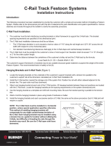
FIGURE 4–TROLLEY COMPONENTS
MAIN WHEELS
4.0" dia.–I-152
6.0" dia.–I-162
WHEEL
MOUNTING
PLATE
RUBBER
BUMPERS
SIDE GUIDE
ROLLERS
TOW ROPE
CONNECTION
SHACKLE
SHOCK
CORD
MOUNTING
PIN
INTERMEDIATE TROLLEY
SHOWN
ANTI–LIFT
ROLLERS
RETAINER
CLAMP PAD
SADDLE
TROLLEY INSTALLATION
There are three types of trolleys: End Clamps, Intermediate, and Tow. The END CLAMP is first on the storage end of the system. It is station-
ary, bolted to the track, and acts as the “bumper” to stop the trolleys when they are moved into storage. See Figure 1–Typical Installation.
INTERMEDIATE trolleys carry the cable or hose. Number and spacing of intermediate trolleys is determined by length of cable/hose and loop
depth. The TOW trolley is last in the string and is attached to the moving machine (crane, machine tool, etc.) serviced by the festoon system.
The Tow Trolley may be replaced by a Tow Clamp bolted directly to the moving machine.
CABLE INSTALLATION
Proper cable installation is the key to a successful festoon system. Refer to the guidlines below while following the cable installation procedure.
1. Check to make sure all trolleys are sized for I-beam installed
previously. Trolleys are furnished to fit a specific beam width.
Clearance between beam flange edge and main wheel flange or side
guide wheel (depending on type of wheel) must be .040" - .080"
on each side. This produces an overall lateral movement of
.080" - .160". All trolleys must roll total length of beam smoothly
with no binding. Trolleys can be adjusted during installation to
compensate for slight beam width variations as follows:
A. Remove wheel mounting assemblies (Fig 5).
B. Add or remove flat washers between the mounting
plate and the threaded boss as required to achieve
proper side clearance (Fig 5).
NOTE:
Quantity of washers must be equal on the same side and
within one from side-to-side on the same trolley.
C. Reinstall mounting plates using Loctite 242 on screw
threads. Torque to 45–50 ft lbs (61-68 Nm).
2. Temporarily position trolleys as they will be stored (Fig 1).
3. Position END CLAMP beneath I-beam. Mark mounting hole
locations and drill through beam flange. Secure with Grade 5
bolts or better. (Fig 6).
CABLE GUIDELINES
Bending Cables
It is best to follow the rule that “BIG BENDS ARE BEST” for
good service and long life. Cable manufacturers vary in apply-
ing a multiplier and we offer the following guide as typical.
Gleason uses the chart below.
Cable O.D. Variations
Variations should be kept to a minimum. Clamping is best
accomplished when all cables are same O.D. or close (Fig 9).
Wide deviation (Fig 10) makes clamping difficult and cable may
not remain in saddle.
CABLE
O.D. MINIMUM
RADIUS MINIMUM
SADDLE DIA.
Under 0.3 in.
Under 0.5 in.
Under 0.8 in.
3 x O.D.
4 x O.D.
5 x O.D.
6 x O.D.
8 x O.D.
10 x O.D.
LARGE BEST SMALL POOR
C
LC
L
FIGURE 9–BEST FIGURE 10–POOR
Balance in Loading Cable
This is important for smooth running, long wheel
bearing life and alignment of components. It is best
to distribute the cable evenly, with the heaviest cables
near the center.
C
L
C
L
FIGURE 11–BEST FIGURE 12–POOR
Flat Cable Stacking
A. Secure clamping
EXTREMELY IMPORTANT: At least 50% of cable
surface must be under clamp pressure.
B. Height consideration
Flat cable stacking best when
width is 3–4 times height, as in
Figures 14 & 15 above. High
stacking can work as long as
equal pressure is applied to all
cables. See Figure 17.
C. Configuration
BIG CABLE ON TOP provides
maximum bending radius,
improves heat dissipation and
takes pulling force when tow
cables are not used. See Fig. 18.
FIGURE 13 FIGURE 14 FIGURE 15
BEST GOOD POOR
100% clamping 50% clamping
FIGURE 16
OK
FIGURE 17
BEST
FIGURE 18–ALIGNING CABLE MARKS
INTERMEDIATE
TROLLEY
CABLE
SADDLE
MARK ON
CABLE
CABLE
FIGURE 5–TROLLEY WIDTH ADJUSTMENT
I–BEAM
.040"–.080"
EACH SIDE
Torque to
90-100 ft. lbs
(122-136 Nm)
Torque to
20-25 ft. lbs
(27-34 Nm)
Torque to
45-50 ft. lbs
(61- 68 Nm)
SIDE GUIDE
WHEEL
Crowned
wheels only
WHEEL
MOUNTING
ASSEMBLY
ADJUST WIDTH BY
ADDING FLAT
WASHERS BETWEEN
WHEEL MOUNTING
ASSEMBLY AND
THREADED BOSSES
4. Weld thrust bar to underside of I-beam (Fig. 6). Bar must be
snug against End Clamp to absorb impact forces.
FIGURE 6–END CLAMP & THRUST BAR
FIGURE 8–OPTIONAL TOW CLAMP
I–BEAM
CUSTOMER SUPPLIED
THRUST BAR
WELDED TO BEAM
END
CLAMP GRADE 5
BOLTS (6-8)
FIGURE 7–TOW ARM CLEARANCE
0.50" min. clearance
top and bottom. Never affix tow arm
rigidly to tow trolley.
0.10" min.
clearance
each side.
CUSTOMER
SUPPLIED
TOW ARM ON
MOVING
MACHINE
TOW
ARM TOW
TROLLEY
RECTANGULAR
TUBE ON
TOW TROLLEY
I–BEAM
TOW ARM
ON MOVING
MACHINE
0.50 min.
TOW
CLAMP
FIGURE 19–TIGHTENING CABLE CLIPS
6 mm,
40–50 in. lbs
(4-6 Nm)
Max.
8 mm,
90–100 in. lbs
(10-11 Nm)
Max.
10 mm,
160–180 in. lbs
(18-20 Nm)
Max.
FIGURE 20–FLAT CABLE LOOP ADJUSTMENT
0.66 x
CABLE
LOOP
DEPTH
CABLE
LOOP
DEPTH
FLAT
CABLE
ONLY –
1/4" SPACE
BETWEEN
CABLES
FLAT
CABLE
ONLY–
1/4" SPACE
BETWEEN
CABLES
NOTE:
When fully tightened,
if ends of clamp
bolts extend beyond
clamps, as shown
below, grind off bolts
until flush to prevent
damage to cables.
Values above are MAXIMUM torque for each size clip.
Some cables may not need to be tightened to
the maximum. Do not over tighten.
CAUTION
2 3
JAM
NUT
6. Install CABLE LOOP CLAMPS. Using one clamp per loop is not
recommended. When using two clamps per loop, clamps must be
staggered (Fig. 20) to prevent them from colliding during system
operation. Clamp tightness is determined by how much the cable or
hose distorts (each type of cable will react differently- 6–12 ft.lbs
[8–16Nm] average). Excessive tightness may damage cables.
IMPORTANT– All cables must be clamped evenly to prevent cables
from sliding in the loop clamps. It will be necessary to build up
smaller cables if they are clamped with larger cables. To do this, self
vulcanizing wrap (Gleason p/n 108578) is recommended.
7. Complete cable termination connections after loops have been
adjusted and loop clamps installed. Avoid connections or splices
at any loop between TOW trolley and FIXED trolley.
NOTE:
When using stacked flat cable, two loop clamps must be used
and loops must be adjusted so that there is space between bottoms
of individual cable loops. See Figure 20.
0.11 x
CABLE
LOOP
DEPTH
5. After cable loops are aligned, clamp cables in place using cable
clamps or clips depending on application. Clamp tightness is
determined by how much the rubber clamp pad distorts the cable or
hose (each type of cable will react differently). Approximately 15 ft.
lbs. (20Nm) is suitable with good quality cable or hose. Allowable
total distortion to get adequate clamping pressure must be determined
by the installer but excessive pressure may damage the cables.
Cable clips should be tightened to 40-50 in. lbs (4-6 Nm) maximum
for clips with 6mm threads, 90-100 in. lbs. (10-11 Nm) for clips
with 8mm thread and 160-180 in. lbs. (18-20 Nm) for clips with 10mm
threads (Fig 19). Tighten jam nut to secure.

Tow Trolley Installation:
System may have either a TOW TROLLEY or a TOW CLAMP. Tow
trolley rolls on beam. Tow clamp is supported by tow arm.
5a. Adjust width of trolley to fit beam as in step 1.
6a. Mount tow arm to moving machine with tow arm end inserted
through tow trolley (Fig 7). Tow arm must protrude through
trolley far enough to absorb any lateral movement. Check
throughout total travel to insure arm does not pull out of trolley.
Tow Clamp Installation:
5b. Check to make sure tow arm will support weight of clamp and
cables as well as horizontal forces imposed on it.
6b. Secure clamp to tow arm using Grade 5 bolts or better. Make
sure that tow clamp bumper lines up with intermediate trolley.
7. Roll all wheeled trolleys along entire length of track. Check
for binding or interference from hanging or joining hardware or
weld bead. Fix areas of concern. NOTE: Check gap in track
at boom hinge. Gap should not exceed 0.25"(6mm) when
boom is lowered and edges should be rounded or tapered to
avoid excessive wear to trolley wheels.
1. Remove all twist from round cable.
2. On cable, mark length required between TOW trolley and
termination junction.
3. Mark CABLE LENGTH LOOPS per General Arrangement
Drawing. Remaining cable is for hookup from FIXED
trolley to termination point.
4. Hang cable. All marks on cable must align with tops of
saddles (Fig 18). Arrange multiple cables per General Arrangement
Drawing or Cable Guidelines (Figs 9–17. above).
FIGURE 4–TROLLEY COMPONENTS
MAIN WHEELS
4.0" dia.–I-152
6.0" dia.–I-162
WHEEL
MOUNTING
PLATE
RUBBER
BUMPERS
SIDE GUIDE
ROLLERS
TOW ROPE
CONNECTION
SHACKLE
SHOCK
CORD
MOUNTING
PIN
INTERMEDIATE TROLLEY
SHOWN
ANTI–LIFT
ROLLERS
RETAINER
CLAMP PAD
SADDLE
TROLLEY INSTALLATION
There are three types of trolleys: End Clamps, Intermediate, and Tow. The END CLAMP is first on the storage end of the system. It is station-
ary, bolted to the track, and acts as the “bumper” to stop the trolleys when they are moved into storage. See Figure 1–Typical Installation.
INTERMEDIATE trolleys carry the cable or hose. Number and spacing of intermediate trolleys is determined by length of cable/hose and loop
depth. The TOW trolley is last in the string and is attached to the moving machine (crane, machine tool, etc.) serviced by the festoon system.
The Tow Trolley may be replaced by a Tow Clamp bolted directly to the moving machine.
CABLE INSTALLATION
Proper cable installation is the key to a successful festoon system. Refer to the guidlines below while following the cable installation procedure.
1. Check to make sure all trolleys are sized for I-beam installed
previously. Trolleys are furnished to fit a specific beam width.
Clearance between beam flange edge and main wheel flange or side
guide wheel (depending on type of wheel) must be .040" - .080"
on each side. This produces an overall lateral movement of
.080" - .160". All trolleys must roll total length of beam smoothly
with no binding. Trolleys can be adjusted during installation to
compensate for slight beam width variations as follows:
A. Remove wheel mounting assemblies (Fig 5).
B. Add or remove flat washers between the mounting
plate and the threaded boss as required to achieve
proper side clearance (Fig 5).
NOTE:
Quantity of washers must be equal on the same side and
within one from side-to-side on the same trolley.
C. Reinstall mounting plates using Loctite 242 on screw
threads. Torque to 45–50 ft lbs (61-68 Nm).
2. Temporarily position trolleys as they will be stored (Fig 1).
3. Position END CLAMP beneath I-beam. Mark mounting hole
locations and drill through beam flange. Secure with Grade 5
bolts or better. (Fig 6).
CABLE GUIDELINES
Bending Cables
It is best to follow the rule that “BIG BENDS ARE BEST” for
good service and long life. Cable manufacturers vary in apply-
ing a multiplier and we offer the following guide as typical.
Gleason uses the chart below.
Cable O.D. Variations
Variations should be kept to a minimum. Clamping is best
accomplished when all cables are same O.D. or close (Fig 9).
Wide deviation (Fig 10) makes clamping difficult and cable may
not remain in saddle.
CABLE
O.D. MINIMUM
RADIUS MINIMUM
SADDLE DIA.
Under 0.3 in.
Under 0.5 in.
Under 0.8 in.
3 x O.D.
4 x O.D.
5 x O.D.
6 x O.D.
8 x O.D.
10 x O.D.
LARGE BEST SMALL POOR
C
LC
L
FIGURE 9–BEST FIGURE 10–POOR
Balance in Loading Cable
This is important for smooth running, long wheel
bearing life and alignment of components. It is best
to distribute the cable evenly, with the heaviest cables
near the center.
C
L
C
L
FIGURE 11–BEST FIGURE 12–POOR
Flat Cable Stacking
A. Secure clamping
EXTREMELY IMPORTANT: At least 50% of cable
surface must be under clamp pressure.
B. Height consideration
Flat cable stacking best when
width is 3–4 times height, as in
Figures 14 & 15 above. High
stacking can work as long as
equal pressure is applied to all
cables. See Figure 17.
C. Configuration
BIG CABLE ON TOP provides
maximum bending radius,
improves heat dissipation and
takes pulling force when tow
cables are not used. See Fig. 18.
FIGURE 13 FIGURE 14 FIGURE 15
BEST GOOD POOR
100% clamping 50% clamping
FIGURE 16
OK
FIGURE 17
BEST
FIGURE 18–ALIGNING CABLE MARKS
INTERMEDIATE
TROLLEY
CABLE
SADDLE
MARK ON
CABLE
CABLE
FIGURE 5–TROLLEY WIDTH ADJUSTMENT
I–BEAM
.040"–.080"
EACH SIDE
Torque to
90-100 ft. lbs
(122-136 Nm)
Torque to
20-25 ft. lbs
(27-34 Nm)
Torque to
45-50 ft. lbs
(61- 68 Nm)
SIDE GUIDE
WHEEL
Crowned
wheels only
WHEEL
MOUNTING
ASSEMBLY
ADJUST WIDTH BY
ADDING FLAT
WASHERS BETWEEN
WHEEL MOUNTING
ASSEMBLY AND
THREADED BOSSES
4. Weld thrust bar to underside of I-beam (Fig. 6). Bar must be
snug against End Clamp to absorb impact forces.
FIGURE 6–END CLAMP & THRUST BAR
FIGURE 8–OPTIONAL TOW CLAMP
I–BEAM
CUSTOMER SUPPLIED
THRUST BAR
WELDED TO BEAM
END
CLAMP GRADE 5
BOLTS (6-8)
FIGURE 7–TOW ARM CLEARANCE
0.50" min. clearance
top and bottom. Never affix tow arm
rigidly to tow trolley.
0.10" min.
clearance
each side.
CUSTOMER
SUPPLIED
TOW ARM ON
MOVING
MACHINE
TOW
ARM TOW
TROLLEY
RECTANGULAR
TUBE ON
TOW TROLLEY
I–BEAM
TOW ARM
ON MOVING
MACHINE
0.50 min.
TOW
CLAMP
FIGURE 19–TIGHTENING CABLE CLIPS
6 mm,
40–50 in. lbs
(4-6 Nm)
Max.
8 mm,
90–100 in. lbs
(10-11 Nm)
Max.
10 mm,
160–180 in. lbs
(18-20 Nm)
Max.
FIGURE 20–FLAT CABLE LOOP ADJUSTMENT
0.66 x
CABLE
LOOP
DEPTH
CABLE
LOOP
DEPTH
FLAT
CABLE
ONLY –
1/4" SPACE
BETWEEN
CABLES
FLAT
CABLE
ONLY–
1/4" SPACE
BETWEEN
CABLES
NOTE:
When fully tightened,
if ends of clamp
bolts extend beyond
clamps, as shown
below, grind off bolts
until flush to prevent
damage to cables.
Values above are MAXIMUM torque for each size clip.
Some cables may not need to be tightened to
the maximum. Do not over tighten.
CAUTION
2 3
JAM
NUT
6. Install CABLE LOOP CLAMPS. Using one clamp per loop is not
recommended. When using two clamps per loop, clamps must be
staggered (Fig. 20) to prevent them from colliding during system
operation. Clamp tightness is determined by how much the cable or
hose distorts (each type of cable will react differently- 6–12 ft.lbs
[8–16Nm] average). Excessive tightness may damage cables.
IMPORTANT– All cables must be clamped evenly to prevent cables
from sliding in the loop clamps. It will be necessary to build up
smaller cables if they are clamped with larger cables. To do this, self
vulcanizing wrap (Gleason p/n 108578) is recommended.
7. Complete cable termination connections after loops have been
adjusted and loop clamps installed. Avoid connections or splices
at any loop between TOW trolley and FIXED trolley.
NOTE:
When using stacked flat cable, two loop clamps must be used
and loops must be adjusted so that there is space between bottoms
of individual cable loops. See Figure 20.
0.11 x
CABLE
LOOP
DEPTH
5. After cable loops are aligned, clamp cables in place using cable
clamps or clips depending on application. Clamp tightness is
determined by how much the rubber clamp pad distorts the cable or
hose (each type of cable will react differently). Approximately 15 ft.
lbs. (20Nm) is suitable with good quality cable or hose. Allowable
total distortion to get adequate clamping pressure must be determined
by the installer but excessive pressure may damage the cables.
Cable clips should be tightened to 40-50 in. lbs (4-6 Nm) maximum
for clips with 6mm threads, 90-100 in. lbs. (10-11 Nm) for clips
with 8mm thread and 160-180 in. lbs. (18-20 Nm) for clips with 10mm
threads (Fig 19). Tighten jam nut to secure.

I-152 & I-162 CONTAINER CRANE FESTOON
INSTALLATION AND MAINTENANCE INSTRUCTIONS
®
END
CLAMP
WELDED
TO BEAM
INTERMEDIATE
TROLLEYS*FIGURE 1
TYPICAL INSTALLATION
FIGURE 2–TROLLEY CLEARANCE
TOW
TROLLEY
SHOCK CORD
(optional)
TOW
ROPE
CABLES/
HOSES CABLE LOOP
CLAMP
(single)
CABLE
LOOP
CLAMP
(double)
FIXED
END
I–BEAM TRACK
Furnished
by customer.
*TRAVEL DISTANCE (ACTIVE TRAVEL) AND
LOOP DEPTH DETERMINE NUMBER OF
INTERMEDIATE TROLLEYS REQUIRED
I–BEAM TRACK INSTALLATION
NOTE:
Special beams with hardened and ground lower flanges should be
considered for high speed, high cycle operation.
1. Mount I–beam track to suitable framework that is strong
enough to support the entire weight of the festoon system (weight
of I–beam, hanging hardware, trolleys and cables or hoses which
will be carried by the festoon). Make sure hardware used for
hanging I–beam will not interfere with free trolley movement.
Refer to Figure 2-Trolley Clearance.
NOTE:
On previously installed track, check all joints and hangers
for clearances shown (Fig 2).
2. Special care should be taken in aligning the I–beam sections to the
crane or hoist support rails. I-beams must be parallel with rails.
ACCEPTABLE SYSTEM TOLERANCES:
HORIZONTAL PLANE: 0.02" per 1.0" across the lower flange width.
RISE/RUN RATIO: 1.0" per 10.0' along track length, maximum of
2.0" for entire SYSTEM LENGTH.
3. Join beams by welding, keeping clearances shown in Figs 2 & 3.
Grind welded joints smooth (Fig 3).
STORAGE DISTANCE ACTIVE TRAVEL
LOOP
DEPTH
OBSTRUCTION
UNDER FESTOON 5" MINIMUM
CLEARANCE
INTRODUCTION
The I-152 & I-162 Container Crane Festoon System was designed to run on a specified width I-beam. System trolleys must have been ordered
for the size I-beam intended for use or the trolleys will not fit.
Each standard installation includes one end clamp, one tow trolley or tow clamp, and a number of intermediate trolleys. Refer to Figure 1-
Typical Installation and Figure 4-Trolley Components and thoroughly familiarize yourself with this product and the terminology used prior to
beginning installation.
NOTICE: Safe and proper operation and long life of the festoon system depend on proper installation, maintenance, loca-
tion and environment. These instructions are intended as a guide but do not cover all possible situations that may arise.
Please refer any questions to Gleason Reel or its authorized representative or distributor.
I–BEAM
CROWNED
WHEELS
MIN. CLEARANCE
ABOVE WHEELS
0.50
INTERMEDIATE
OR
TOW TROLLEY
ANTI–LIFT
WHEELS
NO FASTENERS OR
SPLICE PLATES
ALLOWED ON TOP
OR BOTTOM FACES
OF LOWER FLANGE
FIG 3–WELDED JOINT
GRIND THESE
SURFACES SMOOTH
TOW
CLAMP
TOW ARM
FROM
MOVING
MACHINE
I-BEAM
OPTIONAL TOW CLAMP
1
FIGURE 21–TOW ROPE INSTALLATION
INSTALLING TOW ROPES
Tow ropes “pull” the festoon system along the track, minimizing wear to
and prolonging the life of electrical cables or hoses being carried.
Without tow ropes, the electrical cables are required to act as tension
members which can lead to separated conductors. On multiple cable
applications it is virtually impossible to adjust a festoon system so that all
cables are exactly the same length. Thus all force is directed to the short-
est cable, further compounding the problem. Tow ropes are slightly short-
er than the cables in each loop and no strain is put on the electrical cables
or hoses themselves. See Figure 1–Typical Installation.
1. Mount tow ropes with shackles supplied. See Figure 21.
INSTALLING SHOCK CORDS
Shock Cords are slightly shorter than tow ropes and are used in pairs...two
or four between each trolley. Spring loaded, their function is just as their
name implies; they act as shock absorbers when the festoon trolleys are
beginning to move, limiting undue stress on the tow ropes.
NOTE:
Do not use shock cords unless tow ropes are installed.
1. Mount shock cords on sleeves with M12 thru bolt, flat washers
and ESNA lock nut as shown in Fig 22.
2. Torque to 45-50 ft lbs (61-68 Nm). Metal ends on shock cords
must be free to rotate on sleeves.
TESTING
1. Slowly operate festoon system throughout the total travel.
A. Check for “smooth rolling wheels”, misaligned joints,
hanging or joining hardware interference, and interference of
cable loops with operating area.
B. Make sure tow rope gets tight before electrical cables or hoses.
Adjust length of cable or hose loop, as required.
C. Make sure shock cords are stretched before tow rope gets tight.
2. With festoon trolleys in STORAGE POSITION, check to see that
intermediate trolleys can move back and forth slightly. They must
not be packed “tight” when tow arm is at end of travel.
3. With festoon system FULLY EXTENDED, check each loop to
see that cables are suspended uniformly between trolleys and that
cable load is balanced in saddle.
4. Check all loop clamps. Make sure they are properly positioned,
that all cables are properly clamped, and that no bolts protrude
beyond clamp flanges.
5. Correct all problems before routine operation of crane or hoist.
MAINTENANCE
1. During normal equipment inspection, perform the following
checks and maintenance:
A. Check for wear on trolley wheels, side guides and anti-lift
rollers. Main wheels are supplied with sealed or regreasable
bearings. Sealed bearings do no require maintenance.
Regreasable bearings should be inspected every 500 hours of
operation and regreased if necessary using Chevron SR1#2 or
equal. Side guide and anti-lift rollers are sealed bearings and
do not require maintenance.
B. Check for loose fasteners and nuts, especially the bolts
holding the fixed trolley to the I-beam. Tighten if required.
C. Check for wear or fractured walls on the rectangular tube on
the tow trolley. Repair or replace as necessary. If undue wear
persists, check alignment of tow arm throughout entire travel.
Refer to TROLLEY INSTALLATION, Step 6a.
D. Check condition of bumpers, tow ropes and shock cords.
Replace as required.
E. Check for damaged cable and the tightness of cable
and loop clamps.
TOW ROPES
SHACKLE
TROLLEY
TOW
ROPE
SHACKLE PIN
AND
COTTER PIN
FIGURE 22–SHOCK CORD INSTALLATION
SHOCK
CORD
SHOCK
CORD
TROLLEY
FLAT
WASHER
M12
THRU
BOLT
SLEEVE
LOCK
NUT
®Gleason Reel Corp.
600 S. Clark St.
Mayville, Wisconsin 53050-0026
Phone 920-387-4120 • FAX 920-387-4189
PRINTED IN U.S.A. © COPYRIGHT GLEASON REEL CORP. 1997 BULLETIN 040670.b
HUBBELL
®
A Hubbell Company
4
/