Page is loading ...

INSTALLATION INSTRUCTIONS
STEEL TRACK FESTOON SYSTEM
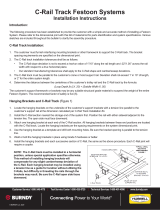
TRACK BRACKET –THREE PIECES
Supports track to cross arms
CROSS ARMS
Support festoon track
NOTE: Models with cross arms only
TRACK SPLICE
Lances in Track to align
with notches in coupler
TOW TROLLEY
(Cross Conductor Kit Only)
Last trolley on moving end of system
INTERMEDIATE
TROLLEYS
FIXED CABLE
CLAMP
Secures cable and
acts as stop on
“non-moving” end
JUNCTION BOX
TROLLEY
(Push Button Kits only)
Has twin trolleys. Used
with push button control
station at moving end of
festoon system
JUNCTION BOX
PENDANT
PUSH BUTTON
CONTROL STATION
(not included)
PENDANT
CABLE
(not included)
INSTALLATION
1. (Models with cross arms only.) Clamp cross arms to supporting I-beam. Spacing
between arms must not exceed 6’ (1.8m) on center. Securely tighten clamps.
2. Hang festoon rail sections from bottom of arms or other suitable support. Use
track splices to join track sections. Carefully level and align track. Securely
tighten all set screws on anchor brackets and splice brackets.
3. Insert end stop into end of track opposite cable xing end. Clamp tightly in place.
4. Insert tow trolley or junction box trolley into cable xing end of track followed by
intermediate trolleys. (See illustrations above.) Inset xed cable clamp into track.
Securely tighten in place.
5. Install cables. Stack with wider cable, if present, next to saddles at top of loop.
Kits assume 3’ loop depth (cable saddle to bottom of loop).
Bulletin No. 63017105.d
Gleason Reel Corp.
600 S. Clark Street
Mayville, WI 53050
www.hubbell-gleason.com
Workplace Solutions
CROSS
ARM
BEAM CLAMPS
Fasten cross arms to I-beam
Includes track nuts
/