Page is loading ...

NOTE:
IN ORDER TO ENSURE THE SAFE USE AND TO ACHIEVE THE
BEST PERFORMANCE, IT IS ESSENTIAL THAT THIS OPERATING
MANUAL IS CAREFULLY READ BEFORE THE RINK IS USED.
0948 English 933.120.412
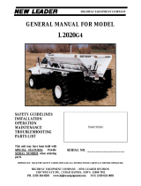
Operating and Parts
manual
RINK
Model 1520
Serial number:

2
T A B L E O F C O N T E N T S
Contents
Page
Safety regulations........................................................................ 3, 4
Short description......................................................................... 5
Technical data.............................................................................. 5
Initial Operating ........................................................................... 6
Operation.............................................................................................. 6
* Before every ride.........................................................................
6
* Coupling and taking off..............................................................
7
* Loading........................................................................................
7
* Spreading....................................................................................
8
Repair and Maintenance
* Lubricate spreader (every 50 operating hours)
...................... 9
* Oil change for conveyor belt gears (every 2 years)
................ 10
* Axle maintenance (every 100 hours)
...................................... 10
*
Adjust distance between the brush and belt
......................... 11
(according to requirements)
* Stretch conveyor belt (in case of slipping)
............................. 11
* Installing and removing the conveyor belt
............................. 12
* Stretching conveyor belt after assembly
................................ 12
* External hydraulic unit
#
........................................................................
13
Spare part list 14,15,16
Technical alterations reserved.
Parts marked with
#
are only available as additional equipment.

3
!
SAFETY REGULATIONS
!
(1) The
Topdresser 1520
is built solely for spreading small-grained, loose material
such as sand, small granular material or similar products.
Any other usage is not in accordance with the indicated use. The manufacturer
does not answer for any damage resulting from incorrect usage. The user alone
has to incur the risk.
Usage in accordance with the intended use also includes compliance with the
manufacturer’s conditions of operation, maintenance and repair.
(2) The spreader is built according to prior art and operationally reliable; however,
the spreader could put life and limb of the operator or of third persons at risk if it
is not used, maintained and repaired by persons who are familiar with it and have
been informed of the dangers.
(3) Any person who, in the plant of the user, is responsible for the operation,
maintenance and repair of the spreader, must have read and understood the
operating instructions and, in particular, this chapter,
Safety Regulations.
Detach the spreader from the towing vehicle during maintenance and service work.
Only use original spare parts from the manufacturer for repairs.
Alongside the references in these operating instructions, the general regulations
for safety and for prevention of accidents must be observed.
When using public roads, the corresponding provisions (e.g. StVZO) will be
in force.
Accompanying persons are not allowed !
(4) A spreader may only be towed along public roads once it holds the necessary
registration. Complete road-worthiness certificate, licensing permit and the
additional safety facilities necessary for this (Lighting set, wheel chocks)
#
are
obtainable on request of the customer.
(5) The operator is obliged to check the spreader for any external damage or
failure before putting it into operation. Any changes (including operating
performance) which might affect safety must immediately be remedied. Changes
to and rebuilding of the spreader (other than changes allowed by the
manufacturer) are, for reasons of safety, not allowed.

4
!
SAFETY REGULATIONS
!
(6) Before starting work, the operator must make himself familiar with all fittings and
controls as well as their functioning.
Spreaders must be properly attached (Risk of injuries !)
Before driving away, check the immediate vicinity and care for a good field of vision.
(7) Whilst spreading is in operation, no one is allowed to enter the loading ramp.
A label with this notice is stuck on both sides of the spreader. This notice must always
be well legible and has to be replaced if damaged!
(8) Whilst the spreader is in operation, do not enter the zone of danger of the spreader since
rotating parts and foreign flying particles might cause any injuries.
(9) Adjusting and repair work on axle (wheel bearings, tyres) must only be undertaken by
properly trained and authorised personnel.
(10) Before starting work on the hydraulic system, it is important that it is without pressure.
The hydraulic hose pipes must be regularly checked and replaced if damaged or worn
out. The replacement hose pipes must conform with the manufacturer’s technical
requirements.
(11) The authorized supporting load on the towing vehicle should be noted.
(12) A sound level of 74 dB (a) is emitted in the immediate vicinity of the brush roller on the
Topdresser 1520.
Used oil damages the environment; please dispose of carefully

5
SHORT DESCRIPTION
The Topdresser 1520 is used for spreading small-grained, loose material, such as sand,
small granular material or similar products. The spreading equipment of the Topdresser
is driven by a gear box with hydraulic motor for conveyor belt and a separate hydraulic
motor for the brush roll. The number of revolutions of the hydraulic system for the
conveyor belt can be continuously adjusted by means of a flow divider. Spreading
density or spreading amount can be determined by the spreader speed and conveyor belt
speed.
Technical Data
Dimensions 1520
L
ength............................................................................................ 3.80 m (150 “)
Width ............................................................................................ 1.87 m ( 74 “)
Height............................................................................................ 1.62 m ( 64”)
Loading capacity............................................................................... 1,9 m³ (2.5 cu yd)
Weights
Authorized total weight ................................................................. 3700 kg (8140 lbs)
Authorized axle load...................................................................... 3200 kg (7040 lbs)
Authorized supporting load........................................................... 500 kg (1100 lbs)
Empty weight............................................................................. ... 850 Kg ( 1870 lbs)
Spreading width................................................................................ 1.40 m ( 55”)
Tyre equipment................................................................................. 19.0 / 45- 17 10PR
Tyre pressure .................................................................................... 0.75- 1.0 bar (10-14 psi)
Speed limit ......................................................................................... 25 km/h (16 mph)
Towing capacity ................................................................................ min 18 Kw (25HP)
Spreading amount.............................................................................
continuously adjustable
Hydraulic connected load
Minimum conveying capacity towing vehicle 25 l/min (9 US gallon/min)
Minimum pressure towing vehicle 150 bar (2100 psi)
The typeplate is fastened onto the front right-hand side of the spreader

6
INITIAL OPERATING
The user is responsible for the transport of the Rink 1520 behind the tractor along the
public streets. Check on the national legislations.
* After the first ride with a full load
- Retighten wheel nuts.
- Check wheel hub clearance and have it adjusted, if necessary.
- Test tyre pressure.
OPERATION
Before every ride
- Check for any externally recognizable failures or damage and repair them.
- Check tyre pressure.
- Check lighting
#
.
- Check conveyor belt tread, reset if necessary. Conveyor belt must not
graze the sides.

7
OPERATION
Coupling and taking off
!
When the spreader has come to a stop, use the change lever brake
#
and secure spreader by means of wheel chocks to prevent it from
rolling away.
- Attach spreader to towing vehicle; for spreaders licensed by the Technical
Control Board, additionally apply the catchment loop around the coupling
mouth of the towing vehicle.
- Carry out hydraulic connection:
Pressure line on right in direction of travel, horizontal; return line on left in
direction of travel, horizontal. Oil circulation is required. In the factory, the
hydraulic system was filled with the hydraulic liquid CG 46.
- With External Oil Supply
#
, mount the plug-on pump on the PTO driver on the
tractor and secure against slippage using the mounted torque support.
(PTO speed 450 rpm).
To ensure optimum operation, the oil temperature should have reached a
temperature of around 25
0
C before starting work (see viewing window at the oil
tank). Check the oil level before starting work (centre of the oil viewing window).
- Adjust the extendable operating facility of the spreader forwards so that the
controls are accessible fron the driving seat.
- Plug the seven-pole plug
#
into towing vehicle.
!
Place brake lever and hydraulic hoses in such a way that they
do not drag to the ground or chafe at the towing vehicle.
- Crank up support tyre lifting the safety flap.
- Disengage change lever brake
#
from the towing vehicle.
Taking off the spreader is carried out in an analogous way.
Loading
- Pay attention to the desired maximum ground pressure.
- When loading, pay attention for the authorized total weight.
- Check for even loading.

8
SPREADING
Controls:
1 Regulator for adjusting the number of revolutions of the brush roll:
Scale distribution 0 to 10
2 Brush roll shift lever:
Middle setting: Drive of the brush roll OFF
Front setting (A): Brush roll spreads at the bottom side
Rear setting (B): Brush roll spreads at the top side
3 Regulator for setting the speed of the conveyor belt:
Scale distribution 0 to 10
4 Conveyor belt shift lever
Middle setting: Drive of the conveyor belt OFF
Front setting (A): Drive of the conveyor belt ON
Rear setting (B): Brief reversing operation of the conveyor belt
Adjusting spreading thickness:
The spreading thickness (mm) is dependent on
- the speed of the towing vehicle
- the speed of the conveyor belt (regulator)
Set the required spreading thickness on a firm surface before starting work.
Adjust the conveyor belt regulator to the desired value.
Adjust the brush roll regulator to the desired value.
Switch on the drive of the brush roll.
Switch on the drive of the conveyor belt.
Switch off the drive takes place in reverse order

9
REPAIR AND MAINTENANCE
Lubricate spreader (every 50 operating hours)
Lubricate with multi-purpose grease:
1 Bearings on both sides of the brush roll
2 Bearings on both sides of the rear conveyor shaft
3 Bearings on both sides of the front conveyor shaft
Bearings without a lubricating nipple require no greasing.

10
REPAIR AND MAINTENANCE
Oil change for conveyor belt gears (every 2 years)
- Unscrew filler screw (1).
- Loosen drain plug (2) from the below inside area and drain off oil.
- Screw on drain plug.
- Add oil SAE 120 to 140 right up to the level of the filler screw (1).
- Screw on filler screw.
.
Axle maintenance (every 100 operating hours)
!
Maintenance work on the axle (brakes, hub clearance etc.) should
only be carried out by fully trained and authorised personnel.
- Retighten wheel nuts.
- Check wheel hub clearance, hub clearance of the brake drum and have it
adjusted, if necessary.
- Check brake setting.
- Test brake lining thickness (min. 3 mm) and, if necessary, have brake
lining replaced.

11
REPAIR AND MAINTENANCE
Adjust distance between the brush rolls (according to requirements)
- Loosen the two screws (4) on both sides of the brush roll.
- Move the brush roll until it slightly contacts the conveyor belt.
- Retighten screws (4).
- Loosen screws (2) and (3) on both sides of the protective plate (1).
- Lower protective plate and set a distance of 30 mm between protective
plate and brush roll.
- Retighten screws (2) and (3).
Stretch conveyor belt (in case of slipping)
-Loosen counternut (1).
-Turn nut (2) once clockwise.
-Tighten counternut.
!
Excessive stretching can reduce the life span of the conveyor belt
.

12
REPAIR AND MAINTENANCE
Installing and removing the conveyor belt
- Remove both triangular plate and lateral cover plate ( A & B).
- Release tension in conveyor belt, evenly loosen the tension bolt (1) on both sides.
- Take off conveyor belt gear, loosen screw (6) frontside.
- Take off eccentric ring (8) at the flange bearing (9) on both sides and unscrew
flange bearing on both sides.
- Remove eccentric bearing (11) at the flange bearing (12) on both sides.
- Use tension bolt (1) to dismantle the flange bearing (12) on the right side.
- Loosen right-sided screws (10) and dismantle the intermediate roller bearings (3).
- Loosen left-sided screws (10).
- Remove front (2) and rear (5) strip roller as well as the intermediate rolls (4).
- Drive out conveyor belt towards the back.
The reassembly takes place in reverse order.
Stretching conveyor belt after assembly
- Once tension has been released in the conveyor belt mark out length
of 1000 mm ( 39.37 “)on both sides.
- Evenly stretch both sides of the conveyor belt with the two tension bolts,
until the marked length reaches 1003 mm (39.49”).
- Leave the conveyor belt to run in for approx. 30 min until it runs in the middle
without grazing the sides, readjust if necessary.
The conveyor belt should not graze the sides. If readjustment is
necessary increase tension on the side which is doing grazing.
Too much tension will reduce the life span of the conveyor belt.

13
REPAIR AND MAINTENANCE
External hydraulic unit
#
Oil change for the hydraulic pump (every 100 operating hours)
- Unscrew filler screw (1).
- Loosen drain plug (2) and drain off oil.
- Screw on drain plug with new gasket.
- Add oli SAE 90 right up to the level of the control screw (3).
- Screw on filler screw with new gasket.
Oil change for the hydraulic tank (according to requirements)
- Unscrew the filling nozzle (1A).
- Release the suction hose (2A) and drain off the oil.
- Screw the suction hose back into place.
- Top up with Bio-Hydraulic oil CG 46 until the level reaches the centre of the
viewing window (3A).
- Screw the filling nozzle back on.
Please note:
!
This is a closed hydraulic circuit. In order to prevent the
ingress of contaminants, the runback filter (4A) must be
replaced every 100 operating hours.

14
Parts list
RINK 1005/ 1010
( Only most important parts are mentioned)
Ordering spare parts
To ensure that your spare parts order can be processed quickly, always
specify the following data when ordering.
- Chassis number / Ident. number
- Model (year of construction if available)
- Part number from respective spare parts list
- Designation
- Order number
Ordering example:
529413 1994 13 Conveyor belt 10524
Chassis number Model Part no. Designation Order no.
/