Altronix 6062 User manual

Type
User manual

Altronix 6062 is a versatile programmable timer designed for various functions requiring timed operations, such as access control, siren cut-off, and guard tour supervision. It features a wide timing range from 1 second to 60 minutes, adjustable via a trimpot. The timer offers flexible relay activation options, allowing the relay to energize at the start or end of the timing cycle. Additionally, it includes a momentary relay activation feature, eliminating the need for multiple timers.

Altronix 6062 is a versatile programmable timer designed for various functions requiring timed operations, such as access control, siren cut-off, and guard tour supervision. It features a wide timing range from 1 second to 60 minutes, adjustable via a trimpot. The timer offers flexible relay activation options, allowing the relay to energize at the start or end of the timing cycle. Additionally, it includes a momentary relay activation feature, eliminating the need for multiple timers.

Overview:
Model DTMR1 programmable timer is suitable for many functions that require a timed operation e.g. Access Control Applications,
Siren/Bell Cut Off Module, Dialer Delay, Guard Tour Supervisory Timer, etc. Some optional functions include: One Shot, Delayed
Release, Delayed Operate, Delayed Pulse and Pulser/Flasher. A new feature has been added which provides a momentary relay activation
at the end of a desired timing cycle. This feature eliminates the need for having to use two (2) timers to achieve this function. Another new
feature will cancel (interrupt) timing cycle and reset timer if desired.
Specifications:
12 or 24VDC operation is selectable.
Quick and extremely accurate time range adjustment
from 1 sec. to 60 min.
LED indicates relay is energized.
Form "C" relay contacts are 8 amps at 120VAC/28VDC.
Current Draw: Stand-by 3mA, Relay Energized 40mA.
Triggers via positive DC (+) voltage, dry contact closure,
or removal of contact closure.
Selectable relay activation at the start or end of the timing cycle.
One (1) second momentary relay activation at the end of
the timing cycle (eliminates the need to use two (2) timers for this function).
Built-in reset feature which cancels timing cycle.
Repeat (pulser/flasher) mode.
Includes Snap Trac (order Altronix model #ST3)
Board dimensions: 3"L x 2.5"W x .75"H
Installation Instructions:
1. Mount DTMR1 in desired location/enclosure.
2. Set proper DC Input Voltage Dip Switch 3: 12VDC ON, 24VDC OFF.
3. Refer to Dip Switch Selection and Jumper Selection Tables for desired functions (e.g.: Timing, Trigger, Pulse).
4. Measure and verify DC input voltage before powering device to ensure proper operation.
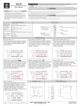
5. Refer to Terminal Identification Table and Typical Applications Fig. 1 thru Fig. 8. for desired wiring connections.
Note: When triggering via a N.O. (normally open), momentary or maintained trigger, connect the
dry contact trigger to Pos (+) and TRG terminals.
When triggering via a N.C. (normally closed), momentary or maintained trigger, connect the trigger to Neg. (-) and TRG
terminals and install a 1K (1,000 ohm) resistor between the Pos (+) and TRG terminals (fig. 8).
Dip Switch Selection Table:
Dip # Off On
1 Relay energizes at start of timing cycle.* Relay energizes at the end of timing cycle.*
2 1-60 minutes timing range. (adjust trimpot) 1-60 seconds timing range. (adjust trimpot)
3 24VDC operating voltage. 12VDC operating voltage.
4Timing begins immediately upon trigger input. Timing starts after removal of trigger input.
* When relay energizes (LED is on) [N.O. & C] switch from open to close and [N.C. & C] switch from close to open.
Jumper Selection Table:
Number Function/Description
J1 Cutting J1 selects the pulser/flasher mode. Relay will flip ON and OFF
continuously in equally set timed intervals when timer is powered up.
J2 Cutting J2 puts timer in delayed output mode. Relay will pulse for 1 second at
the end of a preset timing cycle. *Dip Switch 1 must be ON for this function.
J3 DTMR1 will go through an initial timing cycle when first powered up unless J3 is cut.
If J3 is cut, timing can only be initiated via TRG terminal
Terminal Identification:
Terminal Function/Description
Legend
TRG Applying a positive voltage will activate timing cycle.
Trigger voltage range: 7-12VDC at 12 volt setting, 15-24VDC at 24 volt setting.
-- , + Connect 12 or 24VDC filtered and regulated voltage. Refer to Dip Switch Selection Table for voltage setting.
N.O., C, N.C. Dry form "C" relay contacts are rated 8 amp at 120VAC/28VDC.
DTMR1 - Multi-purpose Timer
Rev. 101501
3.4375
2.75
2.6875
.875
.125
.3125
3.25
.625
ST3 Mechanical Drawing
CUT JI FOR REPEAT J1
MADE IN USA
BKLYN, NY 11220
1 2 3 4
ON
6062
TIMER
TRIG CONTROL 4
12V / 24V 3
SEC. / MIN. 2
RELAY CONTROL 1
TRG --- + NO C NC
1
ALTRONIX CORP.
ON OFF
15
CUT J3 FOR RESET
ON POWER-UP
J3
CUT J2 FOR DELAY PULSE J2
45
60
DTMR1 Typical Applications
Fig. 1 - Timed Door Annunciator:
For this application Switch #1 and Switch #4 should be
in the OFF position.
Fig. 5 - Timed Door Strike:
For this application Switch #1 should be in the OFF
position and Switch #4 should be in the ON position.
Fig. 2 - Guard Tour Supervisory Timer:
For this application Switch #1 and Switch #4 should be
in the OFF position.
Fig. 6 - Timed Shunt for a Door: Use to bypass alarm
contacts.
For this application Switch #1 should be in the OFF
position and Switch #4 should be in the ON position.
CHIME
Pos (+) and Neg (-)
terminals constant 12
or 24VDC
+
--
Normally open door contacts
CUT JI FOR REPEAT J1
MADE IN USA
BKLYN, NY 11220
1 2 3 4
ON
6062
TIMER
TRIG CONTROL 4
12V / 24V 3
SEC. / MIN. 2
RELAY CONTROL 1
TRG --- + NO C NC
1
ALTRONIX CORP.
ON OFF
15
CUT J3 FOR RESET
ON POWER-UP
J3
CUT J2 FOR DELAY PULSE J2
45
60
DIALER OR
TRANSMITTER
Pos (+) and Neg (-)
terminals constant 12
or 24VDC
+
--
Normally open switch contacts
CUT JI FOR REPEAT J1
MADE IN USA
BKLYN, NY 11220
1 2 3 4
ON
6062
TIMER
TRIG CONTROL 4
12V / 24V 3
SEC. / MIN. 2
RELAY CONTROL 1
TRG --- + NO C NC
1
ALTRONIX CORP.
ON OFF
15
CUT J3 FOR RESET
ON POWER-UP
J3
CUT J2 FOR DELAY PULSE J2
45
60
Pos (+) and
Neg (-) termi-
nals constant
12 or 24VDC
+
--
Normally open door contacts
Door Strike
CUT JI FOR REPEAT J1
MADE IN USA
BKLYN, NY 11220
1 2 3 4
ON
6062
TIMER
TRIG CONTROL 4
12V / 24V 3
SEC. / MIN. 2
RELAY CONTROL 1
TRG --- + NO C NC
1
ALTRONIX CORP.
ON OFF
15
CUT J3 FOR RESET
ON POWER-UP
J3
CUT J2 FOR DELAY PULSE J2
45
60
Pos (+) and Neg (-)
terminals constant 12
or 24VDC
+
--
Normally open switch contacts
Door Contacts
Protective Circuit
+
--
+
--
Fig. 3 - Swinger Eliminator:
For this application Switch #1 should be in the OFF
position and Switch #4 should be in the ON position.
Fig. 7 - Bell Cut Off Timer:
For this application Switch #1 should be in the ON posi-
tion and Switch #4 is not used in this application.
CUT JI FOR REPEAT J1
MADE IN USA
BKLYN, NY 11220
1 2 3 4
ON
6062
TIMER
TRIG CONTROL 4
12V / 24V 3
SEC. / MIN. 2
RELAY CONTROL 1
TRG --- + NO C NC
1
ALTRONIX CORP.
ON OFF
15
CUT J3 FOR RESET
ON POWER-UP
J3
CUT J2 FOR DELAY PULSE J2
45
60
Control Panel
12 or 24VDC
BELL
OUTPUT
BELL OR
SIREN
CUT JI FOR REPEAT J1
MADE IN USA
BKLYN, NY 11220
1 2 3 4
ON
6062
TIMER
TRIG CONTROL 4
12V / 24V 3
SEC. / MIN. 2
RELAY CONTROL 1
TRG --- + NO C NC
1
ALTRONIX CORP.
ON OFF
15
CUT J3 FOR RESET
ON POWER-UP
J3
CUT J2 FOR DELAY PULSE J2
45
60
Pos (+) and Neg (-)
terminals constant 12
or 24VDC
+
--
Protective
Circuit
Closed Circuit
Zone on Control Panel
+
--
Fig. 8 - Closed Circuit Trigger Option:
TRG --- +
Power
Supply
+
--
closed
circuit contact
Fig. 4 - Delay Timer: Use for Door Ajar Alarm,
Delayed Activation of Digital Dialer, Defrost Cycle
Timer, etc...
For this application Switch #1 should be in the ON
position and Switch #4 is not used in this application.
CUT JI FOR REPEAT J1
MADE IN USA
BKLYN, NY 11220
1 2 3 4
ON
6062
TIMER
TRIG CONTROL 4
12V / 24V 3
SEC. / MIN. 2
RELAY CONTROL 1
TRG --- + NO C NC
1
ALTRONIX CORP.
ON OFF
15
CUT J3 FOR RESET
ON POWER-UP
J3
CUT J2 FOR DELAY PULSE J2
45
60
Pos (+) and Neg (-)
terminals constant
12 or 24VDC
+
--
Use appropriate contacts to reporting devices
Normally open triggering device
1K resistor
For this application a 1K (1,000 ohm) resistor must be
installed as shown. (resistor not supplied)
Altronix is not responsible for any typographical errors.
140 58th Street, Brooklyn, New York 11220 USA, 718-567-8181, fax: 718-567-9056
website: www.altronix.com, e-mail: [email protected], Lifetime Warranty, Made in U.S.A.
IIDTMR1 J30C
MEMBER
  • Page 1 1
  • Page 2 2

Altronix 6062 User manual

Type
User manual

Altronix 6062 is a versatile programmable timer designed for various functions requiring timed operations, such as access control, siren cut-off, and guard tour supervision. It features a wide timing range from 1 second to 60 minutes, adjustable via a trimpot. The timer offers flexible relay activation options, allowing the relay to energize at the start or end of the timing cycle. Additionally, it includes a momentary relay activation feature, eliminating the need for multiple timers.

Ask a question and I''ll find the answer in the document

Finding information in a document is now easier with AI