Specifications:
• 12VDC to 24VDC operation.
• Positive (+) or negative (–) ultra sensitive trigger
(3VDC to 24VDC @ 20mA minimum).
• DPDT contacts rated at 2A/120VAC/28VDC.
• Relay status LED.
• Remote LED status output.
• Snap track mountable (order part # ST3).
Board dimensions (W x L x H):
2.5”x 3” x 1” (63.5mm x 76.2mm x 25.4mm)
Applications:
• Use with PGM alarm control panel outputs.
• Electronically shunt-alarm zones,
door control or keypads.
• Interfaces with wireless receivers.
• Converts momentary to maintained contacts.
Installation Instructions:
1. Connect aux power to terminals marked [POS (+)] and [NEG (–)].
2. The relay will change state to latch ON or OFF by the application of a positive momentary trigger
voltage to the terminals marked [TRG +] and [POS (+)] or negative momentary trigger voltage to
terminals marked [TRG –] and [NEG (–)].
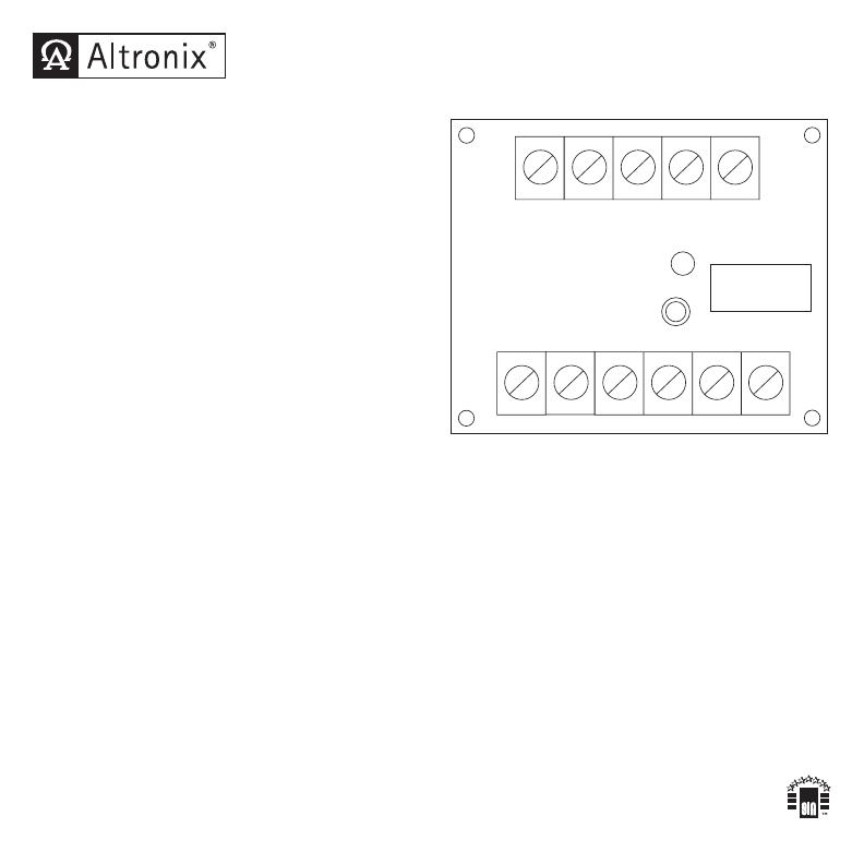
3. Relay status LED is lit when relay is energized. To use a remote LED, connect negative lead of
remote LED to terminal marked [LED], connect positive lead of LED to [POS (+)].
LED TRG -- NEG (-- ) CNO NC
NC
NO
C
POS (+)
TRG +
RBR1224
Electronic Toggle/Ratchet Relay
Altronix is not responsible for any typographical errors. Product specifications are subject to change without notice.
–––––––––––––––––––––––––––––––––––––––––––––––––––––––––––––––––––––––––––––––––––––––––––––––––––––––––––––––––––––––––––––
140 58th Street, Brooklyn, New York 11220 USA | phone: 718-567-8181 | fax: 718-567-9056
IIRBR1224 - Rev. 10803 F21U MEMBER

