Page is loading ...

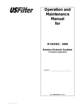
OSMONICS
E4, E4LE, EZ4 SERIES
TM
WATER PURIFICATION
MACHINES
INSTALLATION, OPERATION,
AND MAINTENANCE
MANUAL
GE Infrastructure
Water & Process Technologies


INSTALLATION, OPERATION AND
MAINTENANCE MANUAL
E4, E4LE, AND EZ4 SERIES
WATER PURIFICATION MACHINES
T
ABLE OF CONTENTS
Page
2.0 INSTALLATION 1
2.1 Mounting the Unit 1
2.2 Plumbing 1
2.3 Installing Clean-In-Place Valves 2
2.4 Concentrate Outlet Connections 2
2.5 Feed Water Requirements 2
2.6 Transporting Pure Water (Permeate) to Point-of-Use 3
2.7 Pressure Correction Factors 4
2.8 Electrical 5
2.8.1 Single-Phase Electrical 5
2.8.2 Three-Phase Electrical 5
2.9 Machine Control 6
2.9.1 Economy Model 6
2.9.2 Deluxe Model 6
2.10 Pretreatment for Water Purification 7
2.11 Machine Start-Up Preparation 7
2.12 Machine Start-Up 7
2.13 Temperature Correction Factors 9
2.14 Recovery 10
2.15 Autoflush Timer 11
2.15.1 Programming the Autoflush Timer 11
2.15.2 Setting-Up the Autoflush Timer Clock 11
2.15.3 Programming the Autoflush Timer Clock 12
2.15.4 Programming Twenty-Four Hour or Seven Day Schedules 13
2.15.5 Changing a Program 13
2.15.6 Deleting a Program 13
2.15.7 Troubleshooting the Autoflush Timer 14
2.16 Calibrating the Conductivity Probe 15

Page
2.17 Operation and Maintenance 16
2.17.1 Daily Flushing for the Economy Model 16
2.17.2 Daily Flushing for the Deluxe Model 16
2.18 Pre-Filter Cartridge 17
2.19 Membrane Element Cleaning 17
2.19.1 Step Wise Cleaning 17
2.19.2 Procedure to Clean with a CIP Pump 17
2.20 Suction Cleaning 19
2.21 Changing Out Membrane Elements 20
2.22 Troubleshooting 22
LIST OF FIGURES
Figure Description
2.1 Three-Phase Allen Bradley Motor Starter 6
2.2 Setting-Up the Correct Time on the Autoflush Timer 11
2.3 Programming the Timer 13
2.4 Conductivity Probe Display 15
2.5 Clean-In-Place Pump and Tank Hook-Up 18
LIST OF T
ABLES
Table Description
2.1 Connections 1
2.2 E-Series Feed Water Requirements 3
2.3 Pressure Correction Factors 4
2.4 Flow Specifications for E4-Series Machines 10


1
2.0 INSTALLATION
2.1 Mounting the Unit
When installing your new GE Infrastructure Water & Process Technologies reverse
osmosis (RO) machine, allow at least 45-inches (114 cm) above the machine for mem-
brane element removal and loading. If space is not available, the entire membrane
element housing can be removed for membrane element change outs. If the mem-
brane element housings are to be removed to change out the membrane elements,
at least 6-inches (15.2 cm) is required at the end of each membrane element housing
and 24-inches (61 cm) behind the machine.
2.2 Plumbing
The feed water source must be able to provide water quantity and pressures to main-
tain an operating feed water pressure of 30 - 60 psig (2.1 - 4.1 barg). If the feed water
pressure with the machine is in excess of 60 psig (4.1 barg) or fluctuates by more than
5 psig (0.34 barg) a pressure regulator should be installed up stream of the machine
Inlet. If proper water pressure cannot be maintained to the RO, a booster pump may
need to be installed in front of the pretreatment to provide the proper water quantity
and pressure for the operation of the machine.
Table 2.1
Connections
* Low Energy Membrane Elements
INLET
inches (cm)
0.75 (1.90)
0.75 (1.90)
0.75 (1.90)
0.75 (1.90)
0.75 (1.90)
0.75 (1.90)
E4/EZ4/E4LE*
MACHINE
2200
4400
6600
8800
11000
13200
PERMEATE
inches (cm)
0.50 (1.27)
0.50 (1.27)
0.50 (1.27)
0.75 (1.90)
0.75 (1.90)
0.75 (1.90)
CONCENTRATE
inches (cm)
0.50 (1.27)
0.50 (1.27)
0.50 (1.27)
0.75 (1.90)
0.75 (1.90)
0.75 (1.90)

2.3 Installing Clean-In-Place Valves
NO
TE: Clean-In-Place (CIP) valves are not included with the machine. The CIP
valves must be purchased and installed by the customer.
When installing the CIP valves, a three-way valve should be installed in the inlet feed
stream of the machine. The tees on the permeate and concentrate lines should be
installed with two-way valves. All valves should be installed in a manner that will
allow circulation of the cleaning chemicals through the machine and back to the CIP
container during cleaning.
CA
UTION: If CIP valves are not installed when machine is installed, provisions
must be made to bypass permeate and concentrate to drain for flush-
ing at start-up.
W
ARNING: NEVER OPERATE THE MACHINE WITH THE CONCENTRATE OR PER-
MEATE LINES BLOCKED. SEVERE DAMAGE TO THE UNIT MAY RESULT.
2.4 Concentrat
e Outlet Connections
Connect proper size drain line to the concentrate outlet (Table 2.1) and run to an open
drain. The drain capacity needs to be large enough to properly drain the feed water
flow of the RO. The maximum concentrate back pressure is 60 psig (4.1 barg) for the
RO machine.
CAUTION: Operation above 60 psig (4.1 barg) concentrate back pressure may
damage the machine.
2.5 Feed W
ater Requirements
The following feed water requirements must be met before installing your new E4
machine to ensure quality permeate and extended membrane element life. Refer to
Table 2.2 (E-Series Feed Water Requirements) for feed water information.
2

Table 2.2
E-Series
Feed Water Requirements
* American Standard for Testing Materials
2.6 Transporting Pure Water (Permeate) to Point-of-Use
The pure water, or permeate, is in an aggressive state and should only be transport-
ed from the machine to the point-of-use in food grade flexible nylon, stainless steel
(SS) tubing, or polyvinyl chloride (PVC) material for the inlet, permeate, and concen-
trate piping sizes. Refer to Connections (Table 2.1) for inlet, permeate, and concen-
trate piping sizes.
W
ARNING
: MACHINE DAMAGE MAY OCCUR IF PERMEATE BACK PRESSURE
EXCEEDS 60 PSIG (4.1 BARG) DURING OPERATION.
3
Temperature
Inlet Pressure
Chlorine
(continuous feed)
Operating pH
Silt Density
Index (SDI)
Typical: 50° - 85°F (10° - 29°C)
Limits: 33° - 104°F (0.16° - 40°C)
Minimum: 30 psig (2.1 barg)
Maximum: 60 psig (4.1 barg)
0 parts per million (ppm)
5.5 - 8.5
Less than or equal to 5 to minimize
membrane element fouling and
extend cleaning intervals.
Refer to ASTM* standard D4189.

2.7 Pressure Correction Factors
It is often necessary to operate RO machines with permeate back pressure. Permeate
back pressure will decrease permeate production. See Table 2.3 (Pressure Correction
Factors) to calculate loss of permeate.
Table 2.3
Pressure Correction
Factors
W
ARNING: IF PERMEATE BACK PRESSURE EXCEEDS 60 PSIG (4.1 BARG)
MACHINE DAMAGE MAY OCCUR.
W
ARNING: INSTALLING A CHECK VALVE WILL PREVENT REVERSE FLOW
THROUGH THE MEMBRANE ELEMENT WHEN THE MACHINE IS NOT
IN OPERATION. REVERSE FLOW, WHEN THE MACHINE IS NOT IN
OPERATION, CAN SEVERELY DAMAGE THE MEMBRANE ELEMENTS.
4
BACK PRESSURE
10 psig (0.7 barg)
20 psig (1.4 barg)
30 psig (2.0 barg)
40 psig (2.7 barg)
50 psig (3.4 barg)
60 psig (4.1 barg)
% LOSS OF
PERMEATE FLOW
E4/EZ4 E4LE
5% 10%
10% 20%
15% 30%
20% 40%
25% 50%
30% 60%
PRESSURE
CORRECTION
FACTOR (PCF)
E4/EZ4 E4LE
0.95 0.90
0.90 0.80
0.80 0.70
0.70 0.60
0.60 0.50
0.50 0.40

2.8 Electrical
This RO machine requires two supply voltages; the control voltage and the
pump motor voltage.
2.8.1 Single-Phase Electrical
The control voltage can be connected to either a 115 VAC, 60 Hertz or
220 VAC, 50 Hertz single-phase power supply. The RO control circuit
should always be installed on at least a 15 Amp, single-phase dedi-
cated circuit. Reverse osmosis machines with 115 VAC, single-phase
control voltage include an eight-foot (2.4 m) cord which plugs into a
three-prong grounded receptacle. All machines shipped with a
220 VAC, single-phase control circuit are shipped with an eight-foot
electrical cord, but customers must provide electrical plug.
2.8.2 Three-Phase Electrical
The three-phase pump motor requires a 15 AMP dedicated circuit.
Always verify correct voltage and Amp rating by checking voltage tag
on the starter box or by checking electrical specifications on the
pump. The motor is wired for 460 Volts, 60 Hertz, three-phase voltage
from the factory (Figure 2.1, Three-Phase Allen Bradley Motor Starter).
The pump motor can be rewired to 208 or 230 Volts. If this is done, a
wiring change must be made internally in the pump motor and a
higher amperage relay and starter may need to be installed. All field
wiring must comply with applicable local and national electrical
codes.
After checking the voltage tag on the motor starter to ensure the
available voltage and amperage are correct, connect the provided
three-phase power to the motor starter (Figure 2.1). This can be done
by connecting the three phase power to the top of the starter relay
terminals: L1, L2, and L3. A separate, fused disconnect for the motor
wiring with proper protection for the Horsepower and Amp draw of
the motor is recommended. All field wiring must comply with applic-
able local and national electrical codes. See Figure 2.1 for three-
phase Allen Bradley Starter Hook-Up.
5

Figure 2.1
Three-Phase
Allen Bradley Motor Starter
2.9 Machine Control
2.9.1 Economy Model
To remotely control the Economy Model (ECN) with float switches and/or pre-
treatment lockout, remove the jumper between terminals 4 and 5 and wire in
the float switches or pretreatment components in series. After all field wiring
is complete and complies with local and national electrical codes, move onto
Section 2.10 (Pretreatment for Water Purification).
NO
TE: External control contacts are normally closed, dry contacts.
2.9.2 Deluxe Model
To remotely control the Deluxe Model (DLX), with float switches and/or pre-
treatment lockout, remove the jumper between terminals 2 and 3 and wire in
the float switches and pretreatment in series. After all field wiring is complete
6

7
and complies with local and national electrical codes, move onto Section 2.10
(Pretreatment for Water Purification).
NO
TE: External control contacts are normally closed, dry contacts.
2.10 Pretreatment for W
ater Purification
A water analysis of your feed water should have been performed, as part of the plan-
ning and engineering that went into developing your RO system.
The water analysis will provide information on what type of pretreatment may be
required and what recovery the machine can be run at on the feed water provided. If
the machine is moved to a different water source, a new water analysis should be
taken before operating the machine.
Your RO is designed to operate on tap feed water with an SDI) of 5 or less. The pH
should be in a range of 5.5 - 8.5. Exposure to any levels of chlorine may cause irre-
versible damage to the Thin-layer composite (TLC) polyamide (PA) membrane ele-
ments in your machine. Daily water checks are recommended to ensure the integri-
ty of your pretreatment and RO system.
2.11 Machine S
tart-Up Preparation
Check the function and integrity of your pretreatment equipment. Ensure that your
water softener and activated carbon filters have been leaked checked and properly
flushed, before starting up your RO machine.
CA
UTION: Improperly flushed pretreatment may cause serious RO machine
problems at start-up.
2.12 Machine S
tart-Up
STEPS
1. Turn the feed water supply ON, while checking for leaks in the pretreatment
and inlet feed water lines.
2. Check to ensure power to the motor is de-energized and the ON/OFF button
on the machine is in the OFF position.
3. Plug in the factory-supplied power for the control voltage.
4. For initial start-up, redirect the permeate and concentrate lines to the drain.
5. Open the concentrate and recycle flow control valves two complete turns.
These valves are positioned on the flow control plumbing in the top right rear
section of the machine.

6. Turn the ON/OFF button on the machine ON. System will open allowing water
to flow through the machine to the drain through the permeate and concen-
trate CIP valves.
Let the machine run to drain for 5 - 10 minutes. This provides a wet start-up
of the pump and removes any air in the system.
7. Turn the ON/OFF button on the machine to the OFF position.
8. Re-energize the pump power and trigger the ON/OFF button on the machine
to check rotation of the pump motor. Observing from the back of the pump
motor, pump rotation should be clockwise. If rotation is wrong, de-energize
the pump voltage from the source and switch any two of the three-phase
wires coming in on top of the three-phase starter. Re-energize the pump volt-
age and re-check, to ensure correct rotation for the start-up and operation of
your machine.
W
ARNING: IF THE RO PUMP IS STARTED WITH INCORRECT ROTATION
(i.e., BACKWARDS), A NOTICEABLE DROP IN FLOWS AND
PRESSURES WILL RESULT. IF PUMP MOTOR OPERATES BACK-
WARDS FOR ANY LENGTH OF TIME, PUMP DAMAGE MAY
RESULT.
After correct rotation has been verified, you are now ready to start the
machine and set the flows and pressures.
9. With the recycle and concentrate orifices still two (2) turns open and ade-
quate feed water available, start the machine by turning the ON/OFF button
to the ON position.
10. As the pump starts to build pressure, begin to adjust the orifices in the follow-
ing manner: start by slowly closing the concentrate orifice while slowly open-
ing the recycle valve.
Primary Pressure for Normal Operation at 77°F (25°C)
E4-Series: 220 psi (15.2 bar) at 77°F (25°C)
EZ4/E4LE-Series: 115 psi (7.9 bar) at 77°F (25°C)
While you are doing these valve adjustments, to obtain correct flows and
pressures, observe the primary or pump pressure. The pump pressure, while
adjusting the orifices, should never operate outside of these ranges:
E4-Series Range: 190 - 275 psi (13.1 - 19.0 bar)
EZ4/E4LE-Series Range: 100 - 140 psi (6.9 - 9.6 bar)
8

The concentrate valve is drilled, and when completely closed the machine is
running at the correct concentrate flow for a 75% recovery (Table 2.4, Flow
Specifications for E4-Series Machines).
If the temperature of the inlet feed water is not 77°F (25°C) use the
Temperature Correction Factor Table (Technote 113). The proper adjustment
of the recycle and concentrate valves are critical to the correct operation of
the machine.
CA
UTION: Optimum recovery will vary according to water quality.
2.13 Temperature Correction F
actor
If the temperature of the inlet feed water is not 77°F (25°C), refer to Technote 113 for
Temperature Correction Factors.
NOTE: Optimum recovery will vary according to water quality.
9

2.14 Recovery
The machine flow specifications listed below are based on 25°C (77°F).
Table 2.4
Flow Specifications for
E4-Series Machines
10
2200
50-75%
LPM/GPM
5.8/11.6
5.8/11.6
1.9/0.5
11.5/3.0
7.7/2.0
4400
50-75%
LPM/GPM
11.6/3.06
11.6/3.06
3.9/1.0
23.2/6.1
15.4/4.1
E4-Series
Recovery
Units
Permeate Rate
Concentrate
Rate
(50%)
Concentrate
Rate
(75%)
Feed Rate
(50%)
Feed Rate
(75%)
6600
50-75%
LPM/GPM
17.3/4.6
17.3/4.6
5.8/1.5
34.7/9.2
23.1/6.1
8800
50-75%
LPM/GPM
23.1/6.1
23.1/6.1
7.7/2.0
46.2/12.2
30.8/8.2
11000
50-75%
LPM/GPM
28.9/7.6
28.9/7.6
9.6/2.5
57.8/15.3
38.5/10.2
13200
50-75%
LPM/GPM
34.7/9.2
34.7/9.2
11.6/3.06
69.4/18.3
46.2/12.2

11
2.15 Autoflush Timer
2.15.1 Programming the Autoflush Timer
The Autoflush timer clock operates and displays in real time, but the Autoflush
feature will only work when the RO machine is operating. When the machine
is operating in the Autoflush Mode, the total flow through the machine is
increased. This provides extra cross flow which flushes the loose foulants
from the surface of the membrane elements. When the machine is operating
in the Autoflush Mode a slight drop in permeate production, as well as a
decrease in the primary and final pressures may be observed. An ideal way
to set the timer up is to program ten Autoflush sequences, with a 10 to 15
minute duration, per 24 hours. To do this, follow the procedure below.
2.15.2 Setting Up the Autoflush Timer Clock
IMP
ORTANT: Before proceeding with setting the timer and programming
the unit, press the RESET KEY to clear all data. After press-
ing the RESET KEY, the display may show
A.M., this is in mili-
tary time mode.
If the machine is in Military Time, do the following:
Figure 2.2
Setting-Up the Correct Time
on the Autoflush Timer
SELECTING AM/PM OR MILITARY TIME
After pressing reset, the display may show
A.M.(right). The numbered day symbols will be flash-
ing ON and OFF.
If the display does not show A.M., it is in military time
mode (24:00 hr.). To change to A.M./P.M. mode, press
and hold the h Key and press the
± 1h Key once, A.M. will appear in the display.
If display is in A.M.. mode and military mode is
desired, press and hold the h Key, press the
± 1h Key once.

STEPS
1. While holding down the Clock Key (
⊗
), press the h key to advance to
the current minute.
2. While holding down the Clock Key (
⊗
), press the h key to advance to
the current minute.
3. While holding down the Clock Key (
⊗
), press the h key to advance to
the current minute.
NO
TE: If the h and m keys are held down for longer than 2 seconds,
the numbers will advance rapidly.
If the days are flashing, it indicates the day of the week was not set
when setting the time. The timer cannot be programmed unless the
day of the week is entered. Each year, in the spring, press the Button
to advance the time one hour (Daylight Savings Time). In the fall,
press the button to set the timer back one hour (Daylight Savings
Time).
2.15.3 Programming the Autoflush Timer Clock
This timer will accept up to 20 programs. Each program consists of the fol-
lowing:
1. ON/OFF Command
2. Time of Day (hours and minutes)
3. Single day or multiple days
IMP
ORTANT: The current time of day and day of the week must be set
prior to programming the timer. See Section 2.15.3 (Setting
Up the Autoflush Timer).
12

2.15.4 Programming Twenty-Four Hour or Seven Day Schedules
NOTE: It is helpful to write out the program schedules before programming
the time.
Example:
Figure 2.3
Programming the Timer
2.15.5 Changing a Program
Select the program to be changed with the Prog. Key. A new set of days may
be selected with the Day Key just as in the initial programming. Hour and
minute can be changed with the h and m Keys.
2.15.6 Deleting a Program
To delete one or a few programs: Press the Prog. Key until the desired pro-
gram is displayed:
1. Press the m Key to :59 and press once again to blank out.
2. Press h Key to 11
P.M. and press once again to blank out.
3. Press the Clock Key, (
⊗
) display will flash for several seconds and then
enter the Run Mode.
4. Using the Reset Key will delete ALL programs, the time of day, and day
of the week.
13

2.15.7 Troubleshooting the Autoflush Timer
14
PROBLEM: Days are flashing, pressing any Key does nothing except
“Hand” Key turns output ON and OFF.
SOLUTION: Time of Day and Day of Week have not been set.
See Section 2.15.3 (Setting-Up the Autoflush Timer Clock).
PROBLEM: Time of day was set while holding the Clock Key down, but
days are still flashing.
SOLUTION: Current day of week was not set while holding down
the Clock Key. See Setting-Up the Autoflush Timer Clock
(Section 2.15.2).
PROBLEM: It is 10
A.M. and a ON program for 8 A.M. was entered, but
the output is not ON.
SOLUTION: The ON or OFF was not entered as part of the program.
ON or OFF must be selected.

2.16 Calibrating the Conductivity Probe
STEPS
1. Make sure the calibration meter is in Measure Mode (with the MEAS LED
light ON).
2. Immerse the Conductivity Probe in a 13.00 microSiemens (mS) prepared solu-
tion.
3. Immerse and agitate Conductivity Probe, and wait for the reading to stabilize.
4. Calibrate the meter by adjusting the CAL adjustment screw until the Liquid
Crystal Display (LCD) display reads 13 mS of the solution.
The meter is now calibrated
NO
TE: The alarm function on the conductivity meter is not used on E4/EZ4/E4LE-
Series machines.
Figure 2.4
Conductivity Probe Display
15
/