Page is loading ...

GE OSMONICS
Z SERIES REVERSE OSMOSIS SYSTEM
Operation
and Maintenance Manual
P/N: 1238339 REV. B 16-OCT-03


Z SERIES REVERSE OSMOSIS SYSTEM
Installation, Operation and Maintenance Manual
TABLE OF CONTENTS
Page
CHAPTER ONE: GENERAL INFORMATION 1-1
Section 1.1 The Manual 1-3
1.2 Safety Summary 1-3
1.3 Applications 1-4
1.4 Contraindications 1-4
1.5 Environmental Considerations 1-4
1.6 Theory of Operation 1-6
1.7 Fluid Components 1-6
1.8 Monitors and Controls 1-9
1.9 Optional Equipment 1-12
1.10 Pre Treatment and Other Device RO Interlocks 1-14
1.11 Specifications 1-14
1.11.1 Input Water Requirements 1-14
1.11.2 Flow Rates 1-15
1.11.3 Electrical Requirements 1-15
1.11.4 Dimensions & Weights 1-16
1.11.5 Membrane Performance Characteristics 1-16
1.11.6 Environmental Requirements 1-16
1.12 Disposal 1-17
1.13 Electromagnetic Interference 1-17
1.14 Service Assistance 1-17
1.15 Return Goods Authorization (RGA) 1-18
1.16 Symbols and Abbreviations 1-19
CHAPTER TWO: INSTALLATION GUIDELINES AND INITIAL
SYSTEM START UP
2-1
Section 2.1 Installation Considerations 2-3
2.2 Installation Procedures 2-4
2.3 First Time Start-Up Procedures 2-6
2.3.1 RO Unit 2-6
2.3.2 Rotation Verification (For 3 Phase Motors Only) 2-7
2.3.3 Balance 3 Phase Power 2-7
2.4 Product Water Analysis Procedure 2-8
1238339b
A
A 16 Oct 2003

CHAPTER THREE: SYSTEM OPERATION 3-1
Section 3.1 Daily Start-Up Procedure 3-3
CHAPTER FOUR: ROUTINE MAINTENANCE 4-1
Section 4.1
4.1.1
Routine Maintenance of Z-Series RO System
Daily Maintenance
4-3
4-3
4.1.2 Monthly Maintenance 4-4
4.1.3 Quarterly Maintenance 4-4
4.1.4 Semi-Annual Maintenance 4-5
4.1.5 Annual Maintenance 4-5
4.2
4.2.1
Specific Maintenance Procedures and Instructions
Pump Lubrication Procedure
4-6
4-6
4.2.2 Product Water Divert Verification 4-6
4.2.3 Temperature Setting and Function Test 4-7
4.2.4 Pre-filter Cartridge Replacement Procedure 4-8
4.2.5 Threaded Connection Leak Repair 4-8
4.3 Z-Series Cleaning Indications 4-9
4.3.1 Cleaning Preparation 4-10
4.3.1.1 Cleaning Procedure 4-11
4.3.1.2 Post Cleaning Rinse Procedure 4-12
4.3.1.3 BIOSAN™ (Low pH Cleaner) Cleaning Procedure 4-13
4.4 Disinfection Procedure 4-15
4.4.1 Formaldehyde Disinfection Preparation 4-16
4.4.1.1 Formaldehyde Disinfection Procedure 4-17
4.4.1.2 Post Formaldehyde Disinfection Rinse Procedure 4-19
4.4.2 Peracetic Acid/Peroxide Based Compound
(Renalin®) Disinfection Preparation
4-20
4.4.2.1 Renalin® Disinfection Procedure 4-22
4.4.2.2 Post Renalin® Disinfection Rinse Procedure 4-24
4.5 Product Water Culture 4-25
4.5.1 Product Water Culture Procedure 4-25
4.6 System Storage 4-26
4.6.1 Formaldehyde Storage Procedure 4-26
4.6.2 BIOSAN™ Storage Procedure 4-27
1238339b
B
B 16 Oct 2003

CHAPTER FIVE: TROUBLESHOOTING 5-1
Table of Contents 5-3
Section 5.1 RO Fails to Run 5-5
5.2 RO Runs Intermittently 5-6
5.3 Motor Runs Hot 5-6
5.4 Water Produced While RO is Off 5-7
5.5 Low Waste Pressure 5-7
5.6 Pressure Gauge Vibrates Erratically 5-7
5.7 Excess Product Pressure 5-8
5.8 Product Flow Too Low 5-8
5.9 Product Flow Too High 5-9
5.10 Poor Apparent Water Quality 5-9
5.11 TDS Reading Too High 5-10
5.12 RO Pump Leaks at Inlet End 5-10
5.13 Leaks 5-10
5.14 RO Fails to Draw Disinfectant 5-11
5.15 Product Divert Controller and Valve Malfunction 5-11
CHAPTER SIX: DRAWINGS 6-1
CHAPTER SEVEN: SPARE PARTS LIST 7-1
1238339b
C
C 16 Oct 2003

This page intentionally left blank
1238339b
D
D 16 Oct 2003

Z Series RO System by GE Osmonics
Z Series RO System
CHAPTER ONE:
GENERAL INFORMATION
1238339b – 16Oct03 1 - 1 General Information

Z Series RO System by GE Osmonics
This page intentionally left blank.
1238339b – 16Oct03 1 - 2 General Information

Z Series RO System by GE Osmonics
1.1 The Manual
This manual has been prepared to provide the operator with information and instructions
regarding the installation, use, maintenance, and troubleshooting of the GE Osmonics Z
Series Reverse Osmosis System.
CAUTION:
When used as a medical device, Federal law restricts this device to sale by or on the order
of a physician per CFR 801.109(b)(1).
The manual has been written in narrative form supplemented with schematics and
drawings for clarification. The operator can perform most procedures mentioned in this
manual. Any exceptions will be clearly identified by a qualifying statement.
1.2 Safety Summary
Words in BOLD CAPITAL letters are used to identify key safety or qualifying
statements. A list of all symbols and abbreviations is located at the end of this chapter.
This safety summary does not contain all of the safety statements in the manual. Other
safety statements are included within the manual text and are enhanced and defined as
follows:
WARNING:
Statements identifying conditions or practices that could result in personal injury or loss
of life.
CAUTION:
Statements identifying conditions or practices that could result in equipment or other
property damage.
NOTE:
Statements that provide further clarification.
READ THIS MANUAL:
Prior to operating or servicing this device, this manual must be read and understood.
Keep this and other associated manuals for future reference and for new operators or
qualified service personnel. A note sheet is provided at the end of each chapter for
operators to make notations that may be valuable to other users.
DO NOT REMOVE COVERS OR PANELS:
To avoid electrical shock hazard, do not remove covers or panels when power is supplied
to the device. Do not operate the device when covers or panels are removed.
SHOCK HAZARD:
Connect this device to a proper ground connection in accordance with the National
Electrical Code. DO NOT under any circumstances remove the ground wire or ground
prong from any power plug. DO NOT use an extension cord with this equipment. Keep
the surface under the RO free of water.
1238339b – 16Oct03 1 - 3 General Information

Z Series RO System by GE Osmonics
USE PROPER POWER CONNECTIONS:
Use proper wiring and connection methods to satisfy hospital electrical codes.
DEVICE LABELING:
Do not under any circumstances; remove any Caution, Warning or any other descriptive
labels from the devices until the conditions warranting the label are eliminated.
DO NOT OPERATE IN A FLAMMABLE ATMOSPHERE:
To avoid fire or explosion, do not operate this device in an explosive environment or near
flammable anesthetics.
1.3 Applications
The Z Series Reverse Osmosis (RO) System is designed to purify water by forcing water
through a semi-permeable RO membrane. Water purified by reverse osmosis has had
approximately 95% of the dissolved ions and approximately 99% of most other
contaminants removed. The purified water, referred to as product water or permeate, is
suitable for hemodialysis applications when the quality is equal to or exceeds AAMI
standards.
1.4 Contraindications
WARNING:
GE Osmonics RO systems are not designed, sold, or intended for use in producing
water for injection.
Furthermore, GE Osmonics RO systems are not intended to be used outside of the device
specifications and limitations, as outlined in this manual and other related materials.
1.5 Environmental Considerations
Prior to the installation of the Z-Series RO System, it will be necessary to provide
utilities and create an environment suitable for the trouble free operation of the RO
system and its accessories.
POWER:
The Z-Series unit operates on either single-phase or three-phase power with a variety of
voltages being available. Histories of power failure, power surges, and low line voltages
should be noted and reported to the manufacturer or their agent as they may create
adverse conditions for the operation of equipment.
DRAIN:
A drain outlet is required by the RO system. The drain must have a minimum capacity of
nine gallons per minute of continuous flow for as long as and as often as the RO is
operating. A 2” pipe with a 1/8” per foot slope and a 1” minimum air gap normally
satisfies the waste flow requirement.
1238339b – 16Oct03 1 - 4 General Information

Z Series RO System by GE Osmonics
WATER:
Reverse osmosis systems require a reliable water source. Additionally, it is necessary to
have adequate flow rates and pressure. The Z-Series RO is equipped with safety devices
to shut down the unit when the pressure falls below 10 PSI. If flow rates drop below the
required level the pressure will drop as well, causing the RO to shut down.
It is important to run water at the design flow rate when testing water pressure rather than
reading static pressure. The system automatically restarts when the water pressure is
restored. A brief time delay has been incorporated to prevent telegraphing (short cycling)
caused by the unit rapidly shutting OFF and ON while attempting to operate on marginal
water pressure. During the delay period water will flow through the unit at line pressure
with water being produced at a lesser rate.
TEMPERATURE:
The performance specifications of the RO are based on 77°F (25°C) feed temperature.
Each degree Fahrenheit the feed water temperature falls, the RO product flow decreases
approximately 1.5%, and each degree Celsius drop, the product flow is reduced by 3%
(See Technote 113 for the “Temperature Correction Factors” chart). In climates where
the winter water temperature drops significantly below 77°F it may be necessary to
temper (heat) the water or increase the number of membranes in the RO unit.
WARNING:
The temperature of the tempered water should be monitored closely with a thermometer as
high temperatures can damage the RO membranes and possibly harm the patient. Refer to
the inlet water requirements (Section 1.11.1) for the maximum operating temperature for
the RO.
CAUTION:
It is necessary to keep the RO from freezing to prevent serious damage to the RO unit.
NOISE:
The RO unit does not generate significant noise levels. However, it is advisable to locate
the system in a mechanical room. Hard walls may reflect noise and will make the RO
seem louder.
WATER PURITY:
Plumbing materials can significantly contribute to the contamination of the water.
Metallic pipes (with the exception of ASTM 316 stainless steel) must be eliminated once
the purification process has begun. Schedule 40 or 80 PVC pipes, polypropylene, PVDF,
and other FDA recommended materials are suitable for most grades of purified water.
Care must also be exercised in the choice of a thread sealant. Teflon tape is suitable for
all threaded connections in this system.
WARNING:
Ordinary pipe dope must be avoided since it may leach objectionable and potentially
dangerous impurities into the water.
1238339b – 16Oct03 1 - 5 General Information

Z Series RO System by GE Osmonics
1.6 Theory of Operation
The Z-Series RO is an open-frame mounted reverse osmosis unit which is fully
monitored for pressure, percent rejection and output TDS. The unit includes pre-
filtration to remove gross particles capable of fouling membranes and damaging the high-
pressure pump. The RO pump provides the pressure required to drive water through the
membranes at economical flow rates and improves the membrane's rejection
performance. The fluid controls provide a means of managing required flow rates and
pressures. The following paragraphs detail the function of the components that are used
within the unit.
NOTE:
The Z-Series RO is available in two versions. One is a Direct Feed version that sends
the product water directly to the patient loop. The second is an Indirect Feed version
that feeds a storage tank. Indirect Feed RO units are controlled by tank level controls.
The standard control is a float switch. On high level, an indicator lamp is illuminated on
the front panel of the controller assembly.
1.7 Fluid Components
Temperature Alarm Monitor Probe:
The temperature probe is installed in the direct flow of feed water in the run of a 1” or
larger piping tee after the first piece of pre-treatment equipment before the RO unit. The
probe is used to measure the feed water temperature and is connected to the temperature
switch inside the alarm monitor.
Carbon Filtration:
Carbon Filtration is a required component of a water purification system. Two carbon
filters must be used in series. The carbon tanks are used to remove chlorine / chloramine
from the feed water. When chlorine / chloramine breakthrough is noted after the first
carbon tank, the first tank must be removed, the second put in its place, and a new tank
installed in the second position. Refer to the Carbon Tank Manual for specific operation
and maintenance instructions.
Pre-filters:
The fluid path flows into two Pre-filters, located in the housings on the front of the Z-
Series. They are cartridge type filters with nominal ratings of 5 microns. The purpose of
these elements is to collect any particles larger than 5 microns that may be detrimental to
product water quality and subsequent components in the system. The pressure drop
across the filters is monitored on the inlet and outlet by 0 to 100 PSI panel mounted
gauges.
Pressure Switch:
The low feed water Pressure Switch will shut off the RO pump and turn on an indicator
lamp when the feed water supply is inadequate. The switch automatically resets once the
pressure is restored.
1238339b – 16Oct03 1 - 6 General Information

Z Series RO System by GE Osmonics
Inlet Water Sensor:
The Inlet Water Sensor monitors the quality of the feed water. Input water quality is
compared to the output (product) water and is displayed as "percent rejection" on the
front panel.
Disinfect Inlet Valve:
The Disinfect Inlet Valve is a 1/4 turn ball valve which connects to the input water side
of the pump. The valve is used whenever cleaners or disinfectants are introduced to the
unit. The valve can also be used as a sample port for testing input water for chlorine or
for hardness.
WARNING:
Water from this port is not RO product water and should not be used for dialysis
solutions.
NOTE:
This port is also a good source of pretreated filtered water to fill containers for cleaner or
disinfectants if the RO product water is not available.
High Pressure Pump:
High-Pressure Pump boosts input water pressure to the Reverse Osmosis Membrane
Assembly (ROMA) by as much as 250 PSI. Two types of pumps are available on the Z-
Series units. Both pump styles are multi-stage centrifugal. The standard is of
submersible style; the option has an open drip proof motor. The RO pump discharge
pressure is displayed as membrane supply on a 0 to 600 PSI panel mounted gauge.
Submersible style multi-stage pumps are enclosed in a stainless steel housing. The Air
Bleed Valve is used to purge air from the housing.
Reverse Osmosis Membrane Assembly (ROMA):
Three to six ROMA’s may be included in the Z-Series. Each thin film (TFC) membrane
provides up to 2000 gallons per day for Direct Feed units and 2400 gallons per day of
product water for Indirect Feed units dependent upon feed water quality and
temperature. The product water flow is read on a panel mounted flow meter.
Waste Pressure:
The Waste Pressure is displayed on a 0 to 600 PSI panel mounted gauge as Membrane
Waste. The differential pressure of the supply and the waste is used to determine the
need for cleaning the membranes.
Pressure Regulator Valve:
The Pressure Regulator Valve is an adjustable relief type valve. This valve is located off
of the RO waste stream, and relieves excess waste pressure. The relieved water is then
passed through the Waste Recirculation Flow Meter and fed into the feed water side of
the RO pump.
1238339b – 16Oct03 1 - 7 General Information

Z Series RO System by GE Osmonics
Waste Recirculation Flow Meter:
The Waste Recirculation Flow meter displays the amount of recycled waste water
returned to the inlet of the high-pressure pump. The flow is displayed in a panel mounted
flow meter.
Automatic Flush:
The Automatic Flush feature is intended to reduce the concentrations of suspended solids
at the RO membrane surface, thereby reducing the accumulation of scale. This is
accomplished by forcing water at a high velocity along the membrane surface, diluting or
removing existing concentrations of scale-forming contaminants.
Total Dissolved Solids (TDS) Sensor:
Samples the product water quality via the sensor probe, and the final quality of the
product water is indicated on a digital display on the front panel as TDS in mg/L and
ppm. The monitor is temperature compensated to adjust the display value to changing
water temperature.
Waste Flow Valve:
The Waste Flow Valve is a stainless steel needle valve that controls the waste water flow
to drain. The valve is used to control the ratio of waste water to permeate (% recovery)
and to accelerate the rinse-out of cleaners or disinfectants from the unit. Waste flow is
displayed in a panel-mounted flow meter.
Water Quality Monitoring:
Water Quality Monitoring is monitored in percent rejection and product output TDS.
Percent rejection is a comparison of the inlet water sensor and the product water sensor
and is displayed in a 5 LED array on the front panel. The product water TDS is
monitored with a digital display on the front panel and is temperature compensated. The
high TDS alarm level can be set by a five-position alarm set selector switch. A TDS
exceeding the TDS alarm level selector switch setting will sound an audible alarm, show
a visual alarm indicator on the front panel, and initiate the product divert to drain feature.
Product Water Sensor:
The Product Water Sensor monitors the quality of the product water. This quality is
compared to the input water and is displayed as "percent rejection" on the front panel.
Product Water Flow:
The Product Water Flow is read on a panel mounted flow meter.
Product Divert:
The Product Divert Controller and Valve Assembly is intended to reduce the possibility
of exposure to low quality RO water that may contain excessively high total dissolved
solids (TDS). The valve assembly is located on the product water line after the RO unit
and prior to the next piece of equipment.
RO Bypass Valve:
The RO Bypass Valve is a 1/4-turn ball valve which allows pretreated and pre-filtered
water to feed an optional stand by treatment system.
1238339b – 16Oct03 1 - 8 General Information

Z Series RO System by GE Osmonics
Inlet Solenoid Valve:
The Inlet Solenoid Valve is located on the riser pipe of the Z Series RO and serves to
shut off the water supply to the RO system. It is actuated open when the power switch is
placed in the ON position.
Inlet Water Valve:
The Inlet Water Valve is located after the inlet manifold and before the pre-filter. The
valve allows manual shut off of the water supply to the unit. This valve is also used to
shut off the water for pre-filter changes.
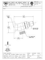
Product Return Valve:
The Product Return Valve is a spring loaded check valve that is set to open at about 2 PSI
over the inlet water pressure. If the Z-Series RO is used to supply water under pressure,
all excess product water will be diverted back to the inlet water line through this valve.
The valve prevents pressurized untreated inlet water from entering the product return
line.
1.8 Monitors and Controls
Power Switch:
The Power Switch is mounted on the front of the control panel. The switch is used when
normal operation of the RO system is desired.
System On Lamp:
The System On indicator lamp is lit whenever the power switch is in the ON position.
Low Feed Pressure Lamp:
The Low Feed Pressure indicator lamp is lit whenever the input water pressure drops
below the inlet pressure switch setting (approximately 10 PSI). The indicator will go out
when the water pressure returns above the pressure switch setting.
Pump Pressure Gauge:
The Pump Pressure Gauge reads the pump discharge pressure from 0 to 600 PSI. It is
used for monitoring during operation and when adjusting the pump pressure. It is used in
conjunction with the waste pressure gauge to evaluate the need to clean the membranes.
Waste Pressure Gauge:
The Waste Pressure Gauge indicates the waste pressure (post membrane) from 0 to 600
PSI. It is used as a reference when adjusting the pump pressure and flow controls. It is
used in conjunction with the pump pressure gauge to evaluate the need to clean the
membranes.
Pre-filter Pressure Gauges:
Pre-filter Pressure Gauges indicate the input water pressure from 0 to 100 PSI. The input
gauge indicates the raw water pressure available to the unit. The output gauge indicates
the pressure available after the pre-filter. The difference (delta) is used to determine
when the filter must be changed.
1238339b – 16Oct03 1 - 9 General Information

Z Series RO System by GE Osmonics
Percent Rejection Display:
The Percent Rejection Display is a 5 LED panel mounted array that indicates how the RO
membranes are performing. The lights correspond to 99%, 95%, 90%, 85%, and >70%
rejection. The 99% light, when illuminated, indicates a need to evaluate the RO system
performance.
CAUTION:
RO units do not normally perform in excess of 99%; verify this reading with an
independent meter and take corrective action if indicated. Some RO membranes will
achieve this level of performance under optimum conditions.
Product Water Total Dissolved Solids (TDS):
The Product Water Total Dissolved Solids (TDS) digital display indicates product water
purity in mg/L (ppm). It is temperature compensated to adjust the value of the display
with changing water temperature for better accuracy.
Less Than 0.5 mg/L Check System Lamp:
The Less Than 0.5 mg/L Check System lamp illuminates when the TDS reading is 0.5
mg/L or less. This indicates a need to evaluate the RO system performance.
CAUTION:
RO units do not normally have TDS less than 0.5 mg/L. Verify this reading with an
independent meter and take corrective action if required. RO membranes may achieve
this level of performance under optimum conditions (good feed water).
Tank Level Controls:
The standard control is a float switch system. An indicator lamp is lit on the controller
assembly and the RO shuts off during a high tank level condition.
NOTE:
Tank Level Controls are used on the Indirect Feed style of RO. However, the Direct
Feed RO can be converted to operate off of a storage tank. Contact GE Osmonics
Technical Service department for details.
Override Switch:
The override switch is used to initiate RO unit operation during a high tank level
condition.
Auto Flush Timer:
The Auto Flush Timer is used to time the length of the automatic flush cycle. The timer
can be adjusted to increase and decrease the length of each cycle.
Alarm Set:
The Alarm Set switch allows the operator to set the TDS levels at which an audible
sounds and product water diverts to drain. The alarm should be set at twice the initial
TDS reading.
1238339b – 16Oct03 1 - 10 General Information

Z Series RO System by GE Osmonics
RO Interlock:
The RO Interlock circuit, when activated, will not allow the RO unit to operate (run). An
electric signal is sent from the RO unit control box (panel) to a normally open micro
switch on the device. These devices are typically part of the pretreatment system. When
the micro switch is closed, the signal returns to the RO unit control box activating the RO
interlock circuit thus disabling RO operation. When the contact is reopened and the
signal no longer is returning to the RO unit control box, the RO interlock circuit is
deactivated and the RO unit will revert to its operational status prior to the lockout. The
devices are connected in series so that if any of the micro switches close, it would
activate the RO interlock circuit and shut down the operation of the RO.
The interlock circuit is also connected to the Temperature Alarm Monitor and will
activate with an alarm condition.
Alarm Mute:
An Alarm Mute switch allows the operator to immediately mute the audible alarm and
address an alarm condition within several minutes before re-sounding occurs. Pressing
the Alarm Mute switch will not mute the audible disinfect alarm produced during
disinfection with a Disinfect Alarm Monitor.
Disinfect key switch:
The Disinfect key switch is used to start the unit for the introduction of
disinfectant/cleaner into the unit. The key switch locks out the inlet solenoid and low-
pressure switch.
CAUTION:
Ensure the RO Unit is prepared for disinfection operations prior to engaging the Disinfect
key switch.
Temperature Alarm Monitor:
The Temperature Alarm Monitor monitors feed water temperature and will shut down the
RO unit if the reading is greater than the alarm set point. The alarm set point is factory
set at 90
o
F and can be adjusted by the user. If high feed water temperature occurs, visual
alarms will illuminate and activate the interlock circuit shutting down the RO unit. The
RO unit will resume operation when the temperature alarm condition is removed.
WARNING:
The monitor is equipped with an override switch to bypass the alarm condition and allow
the RO unit to operate. The override switch is provided for emergency operation only.
When the monitor is alarming and has been overridden, the monitor provides the visual
indication that it is in the override position and is in the alarm mode. When the
temperature returns to below the 90°F limit, the RO unit will revert to its operational
status prior to the alarm and RO lockout. All equipment should be checked for correct
operation prior to resuming normal operation.
1238339b – 16Oct03 1 - 11 General Information

Z Series RO System by GE Osmonics
Product Divert System:
The divert valve rotates open directing water to drain during RO system start-up and/or a
high TDS alarm condition. The opening of the divert valve is communicated with the
illumination of an indicator on the product divert controller. The open divert valve directs
product water to drain and will remain open as long as an alarm condition exists and
close after an approximate two-minute start-up delay or one-minute alarm removal delay.
1.9 Optional Equipment
GE Osmonics offers a number of optional items to adapt the equipment to meet specific
needs. Options are available to increase the volume of water produced or to increase the
quality of the water produced. Options are also available to add control features not
available on the standard systems. Frequently requested options are briefly described in
the following paragraphs. If more information is needed, or if other options are desired,
please consult the factory.
Sanitizing System:
A polyethylene solution tank with a flexible manifold is available for use in
sanitizing/cleaning an RO system. The polyethylene solution tank will handle a wide
range of chemicals and its drop tube design minimizes fumes. The flexible manifold
enables quick and easy connection of the system.
Remote Monitoring
An RO Status Monitor is available in either an external surface mount housing or flush
mount panel for junction box installation, with a variety of monitoring options that
include water quality, storage tank level, distribution loop flow, and disinfect operation.
Normal operation is communicated with the illumination of an In Service and Below
TDS Set Point indicator. Each alarm condition is displayed with the continuous
illumination of the applicable alarm indicator and sounding of an audible alarm. An
Alarm Mute switch allows the operator to immediately mute the audible alarm and
address the alarm condition within several minutes before re-sounding occurs.
The RO Status Monitor reduces the possibility of patient and equipment exposure to
disinfectants with an optional safety feature that requires both the monitor and RO
controller disinfect switches be intentionally and deliberately set for disinfect operations.
An audible alarm sounds when only one of either Disinfect key switches are set to the
disinfect operation and discontinues when both switches are set to disinfect or normal
operation position.
1238339b – 16Oct03 1 - 12 General Information

Z Series RO System by GE Osmonics
Disinfect Alarm Monitor (DAM)
The Disinfect Alarm Monitor reduces the possibility of patient and equipment exposure
to disinfectants. The monitor provides a dependence requiring that Disinfect key
switches, located on the RO Controller and RO Status Monitor, are purposely engaged
prior to introducing disinfectants or cleaning agents into the loop piping. The key switch
dependency ensures that disinfect operations are an intentional and deliberate act.
A disinfect alarm timer controls the duration of the immutable audible disinfect alarm
and prevents RO use for a preset duration (set for 10 minutes upon shipment).
Softener
A water softener system removes calcium, magnesium, and other scale producing
contaminants from the feed water. It is an ion exchange device that substitutes sodium
for larger and more highly charged cations in the feed stream. Their removal reduces the
buildup of scale on the membrane surface. The control valve will initiate the
regeneration of the device and will extract the hardness ions with a brine solution and
rinse the ion exchange bed afterwards. The control valve is normally governed by a time
clock; alternate controls are available from the factory. Scale control by chemical
treatment is also available.
Storage Tank
A storage tank is used to collect RO product water and store it until needed. The reservoir
system has internal features that, with the distribution pump running, continuously wash
the sidewalls and top. Reservoir systems are available with level controls and low-level
alarm monitoring.
Distribution Pumps
Distribution pumps are used to pressurize the RO water for delivery to the point of use.
The pumps, available in both single and multi-staged centrifugals, run continuously to
prevent stagnation of the system. The moving water prevents planktonic microorganisms
from colonizing and results in increased efficiency of disinfection efforts.
Earthquake/Shock Restraints
Shock restraints are available for locations where they may be required by local codes.
Ultraviolet Sterilizers
UV sterilizers are used to kill planktonic (free floating) microorganisms without adding
chemicals to the water. UV Bulbs produce germicidal rays that are 99% efficient at
inactivating microorganisms.
1238339b – 16Oct03 1 - 13 General Information

Z Series RO System by GE Osmonics
Ultra Filters and Sub-micron Filters
Ultra and Sub-micron filters are used to remove undesirable solids from the water.
Normally these filters are used in the distribution loop to remove microorganisms and
media fines. In some instances ultra filters are used in front of RO units to remove
harmful colloids. In these circumstances the ultra filter is employed in a unit similar to
an RO. Most frequently, filtration devices are used in the distribution plumbing. Sub-
micron filters remove particles larger than 0.1 microns; ultra filters remove particles to
0.001 microns and remove endotoxins as well.
1.10 Pre Treatment and Other Device RO Interlocks
1. Pre-treatment provided by a company other than GE Osmonics must come
equipped with a micro switch that is closed when the device goes into
regeneration or backwash. This is required to be able to connect the RO interlock
circuitry to the equipment.
2. Any device provided by another company that is required to be interlocked to the
RO unit so it does not operate (run) during a specific period of the devices
operation must have a normally open micro switch that when activated (closed)
can return a 24VAC signal to the RO unit controller.
1.11 Specifications:
1.11.1 Input Water Requirements
NOTE:
Input water flow rate is dependant upon the size of each RO. In order to determine the
minimum required flow rate of an RO measure in GPM, find the Product flow rate in the
chart below, divide by % recovery, and add 5 GPM.
NOTE:
The maximum water temperature of 38C (100F) is for short-term operation only.
Minimum Maximum
Dynamic Pressure 30 PSI (Typical) 100 PSI
Temperature 1.7°C (35°F) 38°C (100°F)
pH Levels
pH (operating) TF Membranes 4.0 11.0
pH (cleaning) TF Membranes 2.0 11.5
pH w/ chloramines present
(operating) TF Membranes 4.0 8.5
1238339b – 16Oct03 1 - 14 General Information
/