Page is loading ...

User Guide
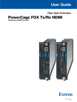
PowerCage 1600 Enclosure
Fiber Optic Products
Modular Power Enclosure for Fiber Optic and Twisted Pair Extenders
68-1717-01 Rev. E
01 19

Safety Instructions
Safety Instructions • English
WARNING: This symbol, , when used on the product, is intended to
alert the user of the presence of uninsulated dangerous voltage within
the product’s enclosure that may present a risk of electric shock.
ATTENTION: This symbol, , when used on the product, is intended
to alert the user of important operating and maintenance (servicing)
instructions in the literature provided with the equipment.
For information on safety guidelines, regulatory compliances, EMI/EMF
compatibility, accessibility, and related topics, see the Extron Safety and
Regulatory Compliance Guide, part number 68-290-01, on the Extron
website, www.extron.com.
Sicherheitsanweisungen • Deutsch
WARNUNG: Dieses Symbol auf dem Produkt soll den Benutzer
darauf aufmerksam machen, dass im Inneren des Gehäuses dieses
Produktes gefährliche Spannungen herrschen, die nicht isoliert sind und
die einen elektrischen Schlag verursachen können.
VORSICHT: Dieses Symbol auf dem Produkt soll dem Benutzer in
der im Lieferumfang enthaltenen Dokumentation besonders wichtige
Hinweise zur Bedienung und Wartung (Instandhaltung) geben.
Weitere Informationen über die Sicherheitsrichtlinien, Produkthandhabung,
EMI/EMF-Kompatibilität, Zugänglichkeit und verwandte Themen finden Sie in
den Extron-Richtlinien für Sicherheit und Handhabung (Artikelnummer
68-290-01) auf der Extron-Website, www.extron.com.
Instrucciones de seguridad • Español
ADVERTENCIA: Este símbolo, , cuando se utiliza en el producto,
avisa al usuario de la presencia de voltaje peligroso sin aislar dentro del
producto, lo que puede representar un riesgo de descarga eléctrica.
ATENCIÓN: Este símbolo, , cuando se utiliza en el producto, avisa
al usuario de la presencia de importantes instrucciones de uso y
mantenimiento recogidas en la documentación proporcionada con el
equipo.
Para obtener información sobre directrices de seguridad, cumplimiento
de normativas, compatibilidad electromagnética, accesibilidad y temas
relacionados, consulte la Guía de cumplimiento de normativas y seguridad
de Extron, referencia 68-290-01, en el sitio Web de Extron, www.extron.com.
Instructions de sécurité • Français
AVERTISSEMENT : Ce pictogramme, , lorsqu’il est utilisé sur le
produit, signale à l’utilisateur la présence à l’intérieur du boîtier du
produit d’une tension électrique dangereuse susceptible de provoquer
un choc électrique.
ATTENTION : Ce pictogramme, , lorsqu’il est utilisé sur le produit,
signale à l’utilisateur des instructions d’utilisation ou de maintenance
importantes qui se trouvent dans la documentation fournie avec le
matériel.
Pour en savoir plus sur les règles de sécurité, la conformité à la
réglementation, la compatibilité EMI/EMF, l’accessibilité, et autres sujets
connexes, lisez les informations de sécurité et de conformité Extron, réf.
68-290-01, sur le site Extron, www.extron.com.
Istruzioni di sicurezza • Italiano
AVVERTENZA: Il simbolo, , se usato sul prodotto, serve ad
avvertire l’utente della presenza di tensione non isolata pericolosa
all’interno del contenitore del prodotto che può costituire un rischio di
scosse elettriche.
ATTENTZIONE: Il simbolo, , se usato sul prodotto, serve ad
avvertire l’utente della presenza di importanti istruzioni di funzionamento
e manutenzione nella documentazione fornita con l’apparecchio.
Per informazioni su parametri di sicurezza, conformità alle normative,
compatibilità EMI/EMF, accessibilità e argomenti simili, fare riferimento
alla Guida alla conformità normativa e di sicurezza di Extron, cod. articolo
68-290-01, sul sito web di Extron, www.extron.com.
Instrukcje bezpieczeństwa • Polska
OSTRZEŻENIE: Ten symbol, , gdy używany na produkt, ma na celu
poinformować użytkownika o obecności izolowanego i niebezpiecznego
napięcia wewnątrz obudowy produktu, który może stanowić zagrożenie
porażenia prądem elektrycznym.
UWAGI: Ten symbol, , gdy używany na produkt, jest przeznaczony do
ostrzegania użytkownika ważne operacyjne oraz instrukcje konserwacji
(obsługi) w literaturze, wyposażone w sprzęt.
Informacji na temat wytycznych w sprawie bezpieczeństwa, regulacji
wzajemnej zgodności, zgodność EMI/EMF, dostępności i Tematy pokrewne,
zobacz Extron bezpieczeństwa i regulacyjnego zgodności przewodnik, część
numer 68-290-01, na stronie internetowej Extron, www.extron.com.
Инструкция по технике безопасности • Русский
ПРЕДУПРЕЖДЕНИЕ: Д а нны й си м в о л, , е сли ук азан
на пр о д ук те, пр е д упреж д а ет по ль зов ателя о нали чи и
неи золи ров анного опасного напряж ени я в нутри к орпуса
прод ук та, к оторое м ож ет при в ести к пораж ени ю
электрическим током.
ВНИМАНИЕ: Д а нны й си м в о л, , е сли ук азан на прод ук те,
пр е д упреж д а ет по ль зов ателя о нали чи и в аж ных и нструк ци й
по эк сплуа таци и и об служ и в ани ю в рук ов од ств е,
при лагаем ом к д анном у оборуд ов ани ю .
Для получения информации о правилах техники безопасности,
со б лю д е ни и но р м а ти в ны х тр е б о в а ни й , эле к тр о м а гни тно й
сов м ести м ости (Э М П/ Э Д С), в озмож ности д оступа и д руги х
в опросах см . рук ов од ств о по безопасности и соблю д ени ю
норм ати в ны х треб ов ани й E xtr on на са й те E xtr on: ,
www.extron.com, ном е р по к а тало гу - 68 -29 0-01 .
安全说明 • 简体中文
警告: 产品上的这个标志意在警告用户该产品机壳内有暴露的危险 电压,
有触电危险。
注意: 产品上的这个标志意在提示用户设备随附的用户手册中有
重要的操作和维护(维修)说明。
关于我们产品的安全指南、遵循的规范、EMI/EMF 的兼容性、无障碍
使用的特性等相关内容,敬请访问 Extron 网站 , www.extron.com,参见
Extron 安全规范指南,产品编号 68-290-01。

Copyright
© 2017-2019 Extron Electronics. All rights reserved.
Trademarks
All trademarks mentioned in this guide are the properties of their respective owners.
The following registered trademarks
®
, registered service marks
(SM)
, and trademarks
(TM)
are the property of
RGBSystems, Inc. or Extron Electronics:
Registered Trademarks
(
®
)
Extron, AVTrac, Cable Cubby, ControlScript, CrossPoint, DTP, eBUS, EDID Manager, EDID Minder, Flat Field, FlexOS, Global Configurator,
GlobalScripter, GlobalViewer, Hideaway, Inline, IPIntercom, IPLink, KeyMinder, LinkLicense, LockIt, MediaLink, MediaPort, NetPA,
PlenumVault, PoleVault, PowerCage, PURE3, Quantum, SoundField, SpeedMount, SpeedSwitch, SystemINTEGRATOR, TeamWork,
TouchLink, V-Lock, VersaTools, VN-Matrix, VoiceLift, WallVault, WindoWall, XTP, and XTPSystems
Registered Service Mark
(SM)
: S3 Service Support Solutions
Trademarks
(
™
)
AAP, AFL (Accu-RateFrameLock), ADSP(Advanced Digital Sync Processing), Auto-Image, CableCover, CDRS(ClassD Ripple
Suppression), DDSP(Digital Display Sync Processing), DMI (DynamicMotionInterpolation), DriverConfigurator, DSPConfigurator,
DSVP(Digital Sync Validation Processing), eLink, EQIP, EverLast, FastBite, FOX, FOXBOX, HyperLane, IP Intercom HelpDesk, MAAP,
MicroDigital, Opti-Torque, ProDSP, QS-FPC(QuickSwitch Front Panel Controller), Room Agent, Scope-Trigger, ShareLink, SIS,
SimpleInstructionSet, Skew-Free, SpeedNav, Triple-Action Switching, True4K, Vector™ 4K , WebShare, XTRA, ZipCaddy, and ZipClip
안전 지침 • 한국어
경고: 이 기호 가 제품에 사용될 경우, 제품의 인클로저 내에 있는
접지되지 않은 위험한 전류로 인해 사용자가 감전될 위험이 있음을
경고합니다.
주의: 이 기호 가 제품에 사용될 경우, 장비와 함께 제공된 책자에 나와
있는 주요 운영 및 유지보수(정비) 지침을 경고합니다.
안전 가이드라인, 규제 준수, EMI/EMF 호환성, 접근성, 그리고 관련 항목에
대한 자세한 내용은 Extron 웹 사이트(www.extron.com)의 Extron 안전 및
규제 준수 안내서, 68-290-01 조항을 참조하십시오.
安全記事 • 繁體中文
警告: 若產品上使用此符號,是為了提醒使用者,產品機殼內存在著
可能會導致觸電之風險的未絕緣危險電壓。
注意 若產品上使用此符號,是為了提醒使用者,設備隨附的用戶手冊中有
重要的操作和維護(維修)説明。
有關安全性指導方針、法規遵守、EMI/EMF 相容性、存取範圍和相關主題的詳細資
訊,請瀏覽 Extron 網站:www.extron.com,然後參閱《Extron 安全性與法規
遵守手冊》,準則編號 68-290-01。
安全上のご注意 • 日本語
警告: この記号 が製品上に表示されている場合は、筐体内に絶縁されて
いない高電圧が流れ、感電の危険があることを示しています。
注意:この記号 が製品上に表示されている場合は、本機の取扱説明書に
記載されている重要な操作と保守(整備)の指示についてユーザーの注意
を喚起するものです。
安全上のご注意、法規厳守、EMI/EMF適合性、その他の関連項目に
つ い て は 、エ ク スト ロ ン の ウェブ サ イト www.extron.com よ り 『 Extron Safety
and Regulatory Compliance Guide』 ( P/N 68-290-01) をご覧ください。
iii

FCC Class A Notice
This equipment has been tested and found to comply with the limits for a Class A digital device,
pursuant to part15 of the FCC rules. The ClassA limits provide reasonable protection against harmful
interference when the equipment is operated in a commercial environment. This equipment generates,
uses, and can radiate radio frequency energy and, if not installed and used in accordance with the
instruction manual, may cause harmful interference to radio communications. Operation of this
equipment in a residential area is likely to cause interference; the user must correct the interference at
his own expense.
NOTE: For more information on safety guidelines, regulatory compliances, EMI/EMF compatibility,
accessibility, and related topics, see the “Extron Safety and Regulatory Compliance
Guide” on the Extron website.
Conventions Used in this Guide
Notifications
The following notifications are used in this guide:
WARNING: Potential risk of severe injury or death.
AVERTISSEMENT : Risque potentiel de blessure grave ou de mort.
CAUTION: Risk of minor personal injury.
ATTENTION : Risque de blessuremineure.
ATTENTION:
• Risk of property damage.
• Risque de dommages matériels.
NOTE: A note draws attention to important information.
Specifications Availability
Product specifications are available on the Extron website, www.extron.com.
PowerCage 1600 Enclosure User Guide • Conventions iv

Contents
Introduction............................................................ 1
About this Guide ................................................. 1
Overview ............................................................ 1
Features ............................................................. 2
PowerCage Enclosure and System ................. 2
PowerCage FOX Fiber Optic Extender Boards 2
PowerCage MTP Twisted Pair Boards ............ 3
System Example ................................................. 4
Installation .............................................................. 5
Enclosure and Rear Panel Features .................... 6
Installing Transmitter and Receiver Boards into the
Enclosure .......................................................... 8
Mounting the Unit ............................................. 10
UL Guidelines for Rack Mounting .................. 10
Rack Mounting ............................................. 10
Cabling and Testing .......................................... 11
Operation .............................................................. 12
Front Panel Features ......................................... 12
Communicating with the Boards: Making an
RS-232 Connection ......................................... 14
PowerCage 1600 Enclosure • Contents v

PowerCage 1600 Enclosure • Contents vi

Introduction
This guide describes the Extron PowerCage 1600 Modular Power Enclosure and how to install,
configure, and operate the enclosure and its optional transmitter and receiver boards.
This section of the guide covers the following topics:
• About this Guide
• Overview
• Features
• System Example
About this Guide
Throughout this guide “PowerCage” and “the enclosure” refer to the PowerCage1600 Enclosure.
NOTE: Observe all applicable building codes and local ordinances when installing the
enclosure.
Overview
The PowerCage 1600 is a rack-mountable, 16-slot enclosure with vents, fans, and an
integrated power supply (or redundant power supplies) that supports a wide range of Extron
fiber optic and twisted pair AV transmitter and receiver boards. It provides an efficient way to
power and mount multiple transmitters and receivers.
PowerCage 1600
COMM
1
POWER
ALARM
2 3 4 5 6 7 8 9 10 11 12 13 14
15 16
1
PSU
2
PSU
1
FAN
2
FAN
COMM
SELECT
CONFIG
TEMP
5A MAX.
100-240V 50/60Hz
PowerCage 1600
Power Supply
PowerCage 1600
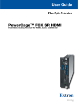
Power Supply
Rear Panel (shown populated with optional redundant power supply)
Front Panel (shown with rack ears installed)
N15778
I.T.E.
1T23
Figure 1. Enclosure Front and Rear Panel Views
PowerCage 1600 Enclosure • Introduction 1

A PowerCage system can include any combination of PowerCage fiber optic (FOX) boards
and PowerCage twisted pair (MTP) boards mounted within the PowerCage enclosure.
Each optional board operates independently of the others to form an integrated system of
individual transmitters and receivers, rather than a matrixed system.
Features
PowerCage Enclosure and System
• Versatile input-output options — The PowerCage 1600 accommodates up to
16single-slot or 8 double-slot FOX fiber optic boards and MTP twisted pair boards.
• 3U, rack-mountable enclosure — The enclosure streamlines installation and
eliminates individual power supplies for each transmitter and receiver.
• Modular, field-upgradeable, and hot-swappable design — The transmitter and
receiver boards, and the primary and redundant power supplies, are hot-swappable,
thus allowing components to be added or replaced at any time without powering
down the system. This is useful for mission-critical applications that require continuous
operation.
• Efficient power management — Each PowerCage board can power down internal
components when no active signal is present, providing increased system efficiency.
• Optional redundant power supply — For continuous, mission-critical applications
where power reliability is crucial, add a redundant power supply, part number 70-784-01.
• Thermal management — The PowerCage enclosure provides channeled air flow to
each board for optimal cooling and reliable operation.
PowerCage FOX Fiber Optic Extender Boards
The fiber optic transmitter and receiver boards:
• Are available in singlemode or multimode versions.
• Support standard definition or high resolution video, HDMI, stereo audio, and RS-232
over a single fiber. They extend high resolution RGB, DVI-D, multi-rate SDI, standard
resolution component, S-video, or composite video extreme distances.
NOTE: Two fibers are needed when transmitting an HDCP signal.
• Deliver pixel-for-pixel image quality for high resolution video. All digital, zero compression
transmission ensures image quality over long distances at high resolutions.
• Provide alarm notification for fiber link loss and can be set up to trigger an external
control system for immediate notification when a fiber link has been lost.
• PowerCage FOX DVI, DVI Plus, and VGA Fiber Optic Extenders are compatible with
and can be mixed and matched with FOXBOX and FOX500 Series transmitters and
receivers for versatile system designs and configurations, including ultra-long distance
DVI-to-analog RGB and RGB-to-DVI conversion.
• Include the following models:
• PowerCage FOX VGA — Fiber Optic Extender for VGA, Audio, and RS-232
• PowerCage FOX DVI, PowerCage FOX DVI Plus — Fiber Optic Extender for
DVI, Audio, and RS-232
• PowerCage FOX 3G HD-SDI — Fiber Optic Extender for Multi-Rate SDI
PowerCage 1600 Enclosure • Introduction 2

• PowerCage FOX AV — Fiber Optic Extender for Video, Audio, and RS-232
• PowerCage FOX HDMI — Fiber Optic Extender for HDMI, Audio, and RS-232
PowerCage MTP Twisted Pair Boards
The twisted pair transmitter and receiver boards:
• Support standard definition or high resolution video, and audio or RS-232 over a
single CAT 5/5e/6 (shielded or unshielded) cable. They transmit and receive high resolution
RGBHV, RGBS, RGsB, RsGsBs, component video, S-video, and composite video long
distances.
• Include the following models:
• PowerCage MTP T 15HD RSA — MTP Twisted Pair Transmitter for VGA and
Audio or RS-232
• PowerCage MTP R 15HD RSA SEQ — MTP Twisted Pair Receiver for VGA and
Audio or RS-232 with Skew Equalization
• PowerCage MTP T AV — MTP Twisted Pair Transmitter for Composite or S-video
and Audio
• PowerCage MTP R AV — MTP Twisted Pair Receiver for Composite or S-video and
Audio
PowerCage 1600 Enclosure • Introduction 3

System Example
The following diagram shows a typical PowerCage 1600 system installation.
FOXBOX 4G Rx DVI Plus
DVI
OVER
TEMP
AUDIO
CONFIG
OPTICAL
Rx
Tx
LINK
LINK
AUDIO
DVI-D OUTPUT
FOXBOX 4G Rx DVI Plus
RS-232
OVER FIBER
ALARM
Tx Rx 1 2
12V
1.0A MAX
POWER
MODE
1
ON
2
FOXBOX 4G Rx DVI Plus
DVI
OVER
TEMP
AUDIO
CONFIG
OPTICAL
Rx
Tx
LINK
LINK
AUDIO
DVI-D OUTPUT
FOXBOX 4G Rx DVI Plus
RS-232
OVER FIBER
ALARM
Tx Rx 1 2
12V
1.0A MAX
POWER
MODE
1
ON
2
FOXBOX 4G Rx VGA
RGB
OVER
TEMP
AUDIO
CONFIG
OPTICAL
Rx
Tx
LINK
LINK
AUDIO
RGB OUTPUT
FOXBOX 4G Rx VGA
12V
1.0A MAX
POWER
MODE
1
ON
2
RS-232
OVER FIBER
ALARM
Tx Rx 1 2
FOXBOX 4G Rx VGA
RGB
OVER
TEMP
AUDIO
CONFIG
OPTICAL
Rx
Tx
LINK
LINK
AUDIO
RGB OUTPUT
FOXBOX 4G Rx VGA
12V
1.0A MAX
POWER
MODE
1
ON
2
RS-232
OVER FIBER
ALARM
Tx Rx 1 2
MTP 1500RL Series
RGB
PEAKING
LEVEL
MIN/MAX
POWER
12V
1.0A MAX
MTP 1500RL 15HD A
OUTPUT
MONO
LR
AUDIO
INPUT
BUFFERED OUTPUT
MTP
MTP
ON
H +
V +
CSYNC
SOG
VIDEO
END
SPARE
MTP 1500RL Series
RGB
PEAKING
LEVEL
MIN/MAX
POWER
12V
1.0A MAX
MTP 1500RL 15HD A
OUTPUT
MONO
LR
AUDIO
INPUT
BUFFERED OUTPUT
MTP
MTP
ON
H +
V +
CSYNC
SOG
VIDEO
END
SPARE
5A MAX.
100-240V 50/60Hz
PowerCage 1600
Power Supply
PowerCage 1600
Power Supply
1 2
REMOTE
RS-232
RS-232
OVER FIBER
Tx Rx
Tx
ALARM
Rx
OUTPUT
RGB
PowerCage
FOX 4G Rx VGA
Tx Rx
LR
AUDIO
1 2
REMOTE
RS-232
RS-232
OVER FIBER
Tx Rx
Tx
ALARM
Rx
OUTPUT
RGB
PowerCage
FOX 4G Rx VGA
Tx Rx
LR
AUDIO
1 2
REMOTE
RS-232
RS-232
OVER FIBER
Tx Rx
Tx
ALARM
Rx
OUTPUT
RGB
PowerCage
FOX 4G Rx VGA
Tx Rx
LR
AUDIO
1 2
REMOTE
RS-232
RS-232
OVER FIBER
Tx Rx
Tx
ALARM
Rx
OUTPUT
RGB
PowerCage
FOX 4G Rx VGA
Tx Rx
LR
AUDIO
AUDIO INPUT
RS-232
Tx Rx
LR
OUTPUT
INPUT
PowerCage
MTP T
15HD RSA
PRE-PEAK
ON
OFF
AUDIO INPUT
RS-232
Tx Rx
LR
OUTPUT
INPUT
PowerCage
MTP T
15HD RSA
PRE-PEAK
ON
OFF
AUDIO INPUT
RS-232
Tx Rx
LR
OUTPUT
INPUT
PowerCage
MTP T
15HD RSA
PRE-PEAK
ON
OFF
AUDIO INPUT
RS-232
Tx Rx
LR
OUTPUT
INPUT
PowerCage
MTP T
15HD RSA
PRE-PEAK
ON
OFF
VGA OPTICAL FIBER UTP/STP
FOX 4G MATRIX 3200
FIBER OPTIC DIGITAL MATRIX SWITCHER
POWER SUPPLY
PRIMARY
REDUNDANT
INPUTS
OUTPUTS
CONTROL
CONFIG
ENTER PRESET
VIEW
ESC
1
2
3 4
5
6 7
8
9
10
11 12
13 14 15 16
17
18
19
20
21
22 23
24
25
26
27 28
29 30 31 32
1
2
3
4
5
6 7
8
9
10
11 12
13 14 15 16
17
18
19
20
21
22
23 24
25
26
27
28
29 30 31 32
MVX SERIES
VGA MATRIX SWITCHER WITH ADPS™
ENTER PRESET VIEW ESC VIDEO AUDIO
CONTROL I/O
OUTPUTS
INPUTS
CONFIG
1 2 3 4 5 6 7 8
1 2 3 4 5 6 7 8
9 10 11 12 13 14 15
9 10 11 12 13 14 15 16
16
OUTPUT
PEAKING
LEVEL
AUDIO RS-232
Tx Rx
OUTPUT
PEAKING
LEVEL
AUDIO RS-232
Tx Rx
Satellite Receivers
Rackmount PCs
Flat Panel Displays
Flat Panel Displays
Building 2
Building 1
MTP R 15HD RSA D
Receivers
MTP 1500RL 15HD A
Receivers
FOXBOX DVI Plus
Receivers
FOXBOX VGA
Receivers
FOX 4G Matrix 3200
Extron
PowerCage 1600
MVX 168 VGA A
N15778
I.T.E.
1T23
Figure 2. An Example PowerCage 1600 System Installation
PowerCage 1600 Enclosure • Introduction 4

Installation
Topics covered in this section of the guide include the following:
• Enclosure and Rear Panel Features
• Installing the Transmitter and Receiver Board into the Enclosure
• Mounting the Unit
• Cabling and Testing
The boards and power supplies are hot-swappable and can be installed or replaced at any
time. However, the most convenient way to proceed with initial installation is as follows:
1. Install the optional redundant power supply and transmitter and receiver boards in the
enclosure.
NOTES:
• Cover all empty board slots; do not leave them open. Securely fasten the
screws for boards and blank panels.
• Use a tool to fully tighten the screws after initial installation and subsequent
removal and replacement of the boards.
2. Mount the enclosure to an equipment rack.
3. Connect cables to the transmitter and receiver boards and to input and output devices.
4. Connect the power cable to the unit and test the system.
Heed the following safety information when installing or servicing the PowerCage system:
CAUTIONS:
ATTENTIONS :
• The PowerCage uses double pole/neutral fusing.
• PowerCage utilise un système de fusible neutre/à double pôle.
• Power must be disconnected before servicing internal components.
• L’alimentation doit être déconnectée avant tout entretien de composants internes.
• Do not leave empty board slots open or uncovered while the unit is powered on.
• Les emplacements de cartes vides ne doivent pas être laissés ouverts ou
découverts lorsque l’unité est en marche.
PowerCage 1600 Enclosure • Installation 5

Enclosure and Rear Panel Features
WARNING: Potential risk of severe injury. Installation and service must be
performed by authorized personnel only.
AVERTISSEMENT : Risque potentiel de blessure grave ou de mort. L’installation
et l’entretien doivent être effectués par le personnel autorisé uniquement.
5A MAX.
100-240V 50/60Hz
PowerCage 1600
Power Supply
N15778
1T23
I.T.E.
Rear Panel
Main
Power
Supply
(standard)
Slot for
Redundant
Power Supply
(optional)
Slots for
Transmitter and Receiver Boards
(up to 16 single-slot or 8 double-slot
optional boards)
Power
Connector
12
3
4
Figure 3. The Rear Panel of the PowerCage 1600 Enclosure
1 Power connector — Connect this port to a 110-240 VAC, 50-60 Hz power source
using a standard IEC power cord.
NOTE: The power supplies and transmitter and receiver boards may be installed or
replaced before or after the unit is powered on.
2 Main power supply — This power supply is included with every PowerCage
enclosure. The front panel PSU 1 LEDs indicate the status of this power supply.
3 Slot for a redundant power supply — An optional redundant power supply can be
installed in this slot. If this second power supply is installed, the front panel PSU 2 LEDs
indicate its status.
4 Slots for transmitter and receiver boards — Slots are numbered from 16 to 1 from
left to right as viewed from the rear of the unit and shown in the following diagram:
5A MAX.
100-240V 50/60Hz
PowerCage 1600
Power Supply
PowerCage 1600
Power Supply
N15778
1T23
I.T.E.
Slot Numbers
Power
Supply
1
Power
Supply
2
16 123456789101112131415
Figure 4. PowerCage 1600 Enclosure Slots
PowerCage 1600 Enclosure • Installation 6


Installing Transmitter and Receiver Boards into the Enclosure
Any combination of up to 16 single-slot or 8 double-slot transmitter or receiver boards can
be installed in the PowerCage enclosure. The quantity and type of boards varies depending
on the configuration for each installation site.
Before installing the boards in the enclosure, refer to the model-specific guide for each
PowerCage transmitter and receiver board you are installing. Some boards have switches
that must be set before installation. The guides describe the features of each board and
how to set up and cable it.
NOTE: The boards are hot-swappable; they can be installed or removed without turning
off or disconnecting the power to the PowerCage enclosure.
CAUTIONS:
ATTENTIONS :
• Use ESD precautions when installing a board to avoid damaging it. Keep the
board in the anti-static bag until it is needed.
• Prenez les précautions ESD lorsque vous installez une carte afin d’éviter de
l’endommager. Gardez la carte dans le sachet dépoussiérant jusqu’à ce que vous
en ayez besoin.
• Use proper grounding techniques during installation.
• Utilisez des techniques de mise à la terre correctes pendant l’installation.
NOTE: The main power supply or redundant power supply boards should be installed
and not removed except during replacement. Power supply board removal and
replacement for testing purposes should be avoided or kept to a minimum.
1. Where applicable, remove as many blank plates or previously installed boards from the
rear of the PowerCage Enclosure as necessary to accommodate the number of new
boards to be installed. Save the screws for use in step 3.
PowerCage 1600 Enclosure • Installation 8

2. Hold the board with the signal connectors towards you and the LED at the top, and
align the top and bottom grooves of the board with the slide posts in the selected
enclosure slot, as shown in the following figure:
MONO
AUDIO OUTPUT
12
SHARP
GAIN
Y/VID
C
INPUT
PowerCage
MTP R AV
Tx Rx
HD/SDI INPUT HD/SDI OUTPUTS
MODE
PowerCage
FOX 3G HD-SDI
1 2
REMOTE
RS-232
RS-232
OVER FIBER
Tx Rx
Tx
ALARM
Rx
OUTPUT
RGB
PowerCage
FOX RGB
Tx Rx
LR
AUDIO
5A MAX.
100-240V 50/60Hz
N157 78
C
US
LIST ED
1T23
I.T.E.
Screws
(2 per board)
1 2
REMOTE
RS-232
RS-232
OVER FIBER
Tx Rx
Tx
ALARM
Rx
OUTPUT
RGB
PowerCage
FOX RGB
Tx Rx
LR
AUDIO
Align board and
slide into slot.
Figure 5. Inserting Boards into the PowerCage Enclosure
3. Carefully slide the board into the slot, aligning the two tabs on the lower front end of the
board with the matching ports in the enclosure. Push the board firmly into place.
Tighten the screws to secure the board in place.
NOTE: Use a tool to fully tighten the screws after initial installation and subsequent
removal and replacement of the boards.
4. Repeat steps 2 and 3 for all boards needing installation.
PowerCage 1600 Enclosure • Installation 9

Mounting the Unit
The PowerCage enclosure can be mounted in a standard equipment rack before or after
installing transmitter and receiver boards. To rack mount the enclosure, follow the UL
guidelines and refer to the diagram in the “Rack Mounting” section.
UL Guidelines for Rack Mounting
The following Underwriters Laboratories (UL) guidelines pertain to the safe installation of the
equipment in a rack.
1. Elevated operating ambient — If installed in a closed or multi-unit rack assembly,
the operating ambient temperature of the rack environment may be greater than room
ambient. Therefore, consider installing the equipment in an environment compatible with
the maximum ambient temperature specified by the manufacturer [Tma = +32 to +122 °F
(0 to +50 °C)].
2. Reduced air flow — Installation of the equipment in a rack should be such that the
amount of air flow required for safe operation of the equipment is not compromised.
3. Mechanical loading — Mounting of the equipment in the rack should be such that a
hazardous condition is not achieved due to uneven mechanical loading.
4. Circuit overloading — Consideration should be given to the connection of the
equipment to the supply circuit and the effect that overloading of the circuits might have
on overcurrent protection and supply wiring. Appropriate consideration of equipment
nameplate ratings should be used when addressing this concern.
5. Reliable earthing (grounding) — Reliable earthing of rack-mounted equipment should
be maintained. Particular attention should be given to supply connections other than
direct connections to the branch circuit (such as the use of power strips).
Rack Mounting
CAUTION: Leave open space of at least 1U on the top, bottom, and sides of the
enclosure to allow adequate air circulation and prevent overheating. Do not cover the
vents or fans.
ATTENTION : Laissez un espace ouvert d’au moins 1U en haut, en bas, et sur les
côtés du boîtier afin de permettre une circulation de l’air suffisante et d’empêcher la
surchauffe. Ne pas couvrir les conduits ou les ventilateurs.
NOTE: Air flows through the enclosure from right to left, as viewed from the front panel.
To rack mount the enclosure:
1. Attach the mounting brackets to the sides of the enclosure, as shown in figure 6. The
brackets can be attached at either the front or the back.
2. Fasten the brackets to the rack.
PowerCage 1600 Enclosure • Installation 10

Tx Rx
HD/SDI INPUT HD/SDI OUTPUTS
MODE
1 2
REMOTE
RS-232
RS-232
OVER FIBER
Tx Rx
Tx
ALARM
Rx
VIDEO
1
2
3
4
Tx Rx
LR
AUDIO
1 2
REMOTE
RS-232
RS-232
OVER FIBER
Tx Rx
Tx
ALARM
Rx
OUTPUT
RGB
Tx Rx
LR
AUDIO
Tx Rx
HD/SDI INPUTHD/SDI OUTPUTS
MODE
1 2
REMOTE
RS-232
RS-232
OVER FIBER
Tx Rx
Tx
ALARM
Rx
VIDEO
1
2
3
4
Tx Rx
LR
AUDIO
1 2
REMOTE
RS-232
RS-232
OVER FIBER
Tx Rx
Tx
ALARM
Rx
OUTPUT
RGB
Tx Rx
LR
AUDIO
1 2
REMOTE
RS-232
RS-232
OVER FIBER
Tx Rx
Tx
ALARM
Rx
VIDEO
1
2
3
4
Tx Rx
LR
AUDIO
1 2
REMOTE
RS-232
RS-232
OVER FIBER
Tx Rx
Tx
ALARM
Rx
OUTPUT
RGB
Tx Rx
LR
AUDIO
5A MAX.
100-240V 50/60Hz
3-U Rack Mount Bracket
(use four mounting holes)
Figure 6. Attaching Brackets and Rack Mounting the Enclosure
Cabling and Testing
Refer to the setup guides and user guides for the models of transmitter and receiver boards
you are installing for details on how to cable and set up each board.
• Some fiber optic boards include pass-through RS-232 connections.
• Some boards have mode switches.
• Some MTP twisted pair boards include picture adjustment or peaking controls.
PowerCage 1600 Enclosure • Installation 11

Operation
The following topics are covered in this section of the guide:
• Front Panel Features
• Communicating with the Boards: Making an RS-232 Connection
Front Panel Features
The front panel of the PowerCage 1600 Enclosure provides a variety of LED status
indicators, a selection button, and a port for communicating with an active installed board.
See the diagram below and the following descriptions for details.
PowerCage 1600
COMM
1
POWER
ALARM
2 3 4 5 6 7 8 9 10 11 12 13 14 15 16
1
PSU
2
PSU
1
FAN
2
FAN
COMM
SELECT
CONFIG
TEMP
Front Panel
1
Board Status LEDs
(for multi-function boards,
up to 16 optional boards)
Power Supply
Status LEDs
3
Fan
Status
LEDs
Configuration
Port
(RS-232)
Communication
Selection
Button
System
T
emperature
Status LED
6
542
Figure 7. The PowerCage 1600 Enclosure Front Panel
1 Board status LEDs (Comm, Power, Alarm) — There is one set of these LEDs for
each of the 16 rear panel slots that is available for boards. If a board is installed in the
identically-numbered slot, the LEDs light under the following circumstances:
COMM
1
POWER
ALARM
Alarm LED —
Lights when the receiving (Rx) fiber link on a PowerCage FOX board is
broken
or disconnected. This feature depends on the model of PowerCage board.
This LED is not used for PowerCage MTP boards.
Comm LED — Lights when the corresponding board is selected (see
d
, Comm
Select
button) and, for FOX boards, can be communicated with via the Config port (
e
).
Power LED — Lights when the corresponding board receives power.
NOTE: For a double-slot board, the status LEDs light only for the lower-numbered slot.
PowerCage 1600 Enclosure • Operation 12

2 Power supply (PSU) status LEDs — These pairs of LEDs correspond to the primary
(included) power supply and the redundant (optional) power supply. For each power
supply, the LEDs light as follows:
1
PSU
2
PSU
Alarm LED —
Lights when the power supply malfunctions, such as providing an
overvoltage (14 VDC or more) or undervoltage (10.5 VDC or less)
.
Power LED — Lights when the power supply receives power.
3 Fan status LEDs — These LEDs indicate whether the fans that cool the enclosure are
operating.
1
FAN
2
FAN
Alarm LED —
Lights when the corresponding fan malfunctions
.
Power LED — Lights when the corresponding fan receives power.
4 Communication selection (Comm Select) button — Press this button to select the
desired board to connect to the Config port (
5
). With each button press, the serial
connection changes from one active, installed board to the next. The Comm LED
(see
1
) for the selected board lights.
NOTES:
• When unit power is cycled (removed then restored), the serial connection
returns to the board in the lowest-numbered slot. A double-slot board
connects to the lower-numbered slot.
• The Comm LED lights for each installed, powered board as its slot is selected,
regardless of the type of board. However, RS-232 communication works
only with FOX boards; commands and queries cannot be sent to or passed
through the MTP boards.
5 Configuration and communication (Config) port — For RS-232 serial
communication with any installed board, connect a Windows-based PC or an RS-232
control system to this 2.5 mm mini stereo-style (tip-ring-sleeve) jack. Use the Extron
9-pin D to 2.5 mm stereo mini TRS RS-232 cable (part number 70-335-01, shown in
the following figure).
5
1
9
6
6 feet
(1.8 m)
Part 70-335-01
Sleeve (Gnd)
Ring
Tip
9-pin D Connection TRS Plug
Pin 2 Computer's Rx line Tip
Pin 3 Computer's Tx line Ring
Pin 5 Computer's signal ground Sleeve
Figure 8. 9-pin D to 2.5 mm Stereo Mini TRS RS-232 Cable
PowerCage 1600 Enclosure • Operation 13

RS-232 protocol varies depending on the board being communicated with, but all
boards accept this basic set of protocol:
• 9600 baud • 1 stop bit • no parity
• 8 data bits • no flow control
NOTE: This port allows serial communication to the boards only, not to the
enclosure, itself. The power supply and fan status LEDs provide feedback
about the condition of the enclosure.
6 Temperature status (Temp) LED — This LED lights when the unit as a whole is
operating at a dangerously high temperature (approximately 167 °F [75 °C]) and
equipment damage is imminent. If the Temp LED lights, power down the unit, ensure
adequate ventilation, and allow the PowerCage system to cool before restoring power.
Communicating with the Boards: Making an RS‑232 Connection
RS-232 communication works only with FOX boards; commands and queries cannot be
sent to or passed through the MTP boards. To communicate with and check some basic
information about individual installed transmitter or receiver boards, do the following:
1. Connect the serial port of a Windows-based PC or an
RS-232 control device to the front panel Config port
on the PowerCage system, and power on both
devices.
2. Set the serial connection as follows:
• 9600 baud • 1 stop bit • no parity
• 8 data bits • no flow control
3. Press the Comm Select button to select the desired
board to connect to the Config port. The Comm LED
for the selected board lights. With each button press,
the serial connection changes from one installed board
to the board installed in the next higher-numbered slot,as
shown in the following figure. (The next slot may not be
numbered contiguously with the previously selected board.)
PowerCage 1600
COMM
SELECT
CONFIG
TEMP
RS-232
PC or RS-232
Control Device
Front Panel
PowerCage 1600 Enclosure • Operation 14
/