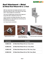
Grape Solar GS-1060-R-ASD Installation guide

Type
Installation guide

This manual is also suitable for

EZ Roof Mount
Attachments
Pub. D10011-V007
Copyright 2018
EZ Roof Mount Attachments
With L-Foot, Standoffs and Variants
EZ Roof Mount
Attachments
2 of 14
Please read carefully before installing
Patent # US8122648B
SunModo’s EZ Roof Mount Attachments can be used to mount PV panels on pitch roofs.
All installations shall be in accordance with NEC requirements in the USA.
Table of Contents
Installer Responsibility: .......................................................................................................................... 3
Safety: ................................................................................................................................................... 3
Specifications: ....................................................................................................................................... 3
Lag Pull-Out Capacities: ........................................................................................................................ 3
EZ Roof Mount Series: ........................................................................................................................... 4
Primary Materials: .................................................................................................................................. 5
Tools Required for Installation: .............................................................................................................. 8
Torque Values: ...................................................................................................................................... 9
Flashing Placement: ............................................................................................................................ 10
Sealant Application: ............................................................................................................................. 10
Installation Instructions: ....................................................................................................................... 11
EZ Roof Mount Kit K10068-XXX ...................................................................................................... 11
EZ Roof Mounting Standoff Kit K10070-XXX .................................................................................... 12
EZ Roof Mount with C-Bracket Kit K12005-001 ................................................................................ 12
Optional Mounting Instructions: ............................................................................................................ 13
EZ Roof Mount Kit K10068-BK7 ....................................................................................................... 13
SunModo Corporation:
Vancouver, Washington
www.SunModo.com
Ph: 360-844-0048
Document Number D10011-V007
©2018 SunModo Corp.
File 0248
EZ Roof Mount
Attachments
3 of 14
Installer Responsibility:
Before ordering and installing materials, all system layout dimensions should be confirmed by field measurements. SunModo
reserves the right to alter, without notice, any details, proposals or plans. Any inquiries that you may have concerning installation
of the PV system should be directed to your SunModo Sales representative. Consult SunModo Sales for any information not
contained in this manual. This manual is intended to be used as a guide when installing SunModos EZ Roof Mount System on
pitched roofs. It is the responsibility of the installer to ensure the safe installation of this product as outline herein.
Installer shall employ only SunModo products detail herein. The use of non SunModo components can void the warranty
and cancel the letters of UL compliance.
Installer shall guarantee that screws and anchors have adequate pullout strength and shear capacities.
Installer shall adhere to the torque values specified in this Instruction Manual.
Installer shall use anti-seize compound, such as Permatex anti-seize, lubricant is recommended for all threaded parts.
Installer is responsible to install solar panels over a Fire Resistant roof covering rated for the application.
Installer is responsible to determine that the roof, its rafters, connections, and other architectural support components can
sustain the array under all code level loading conditions.
Installer shall adhere to all relevant local or national building codes. This takes account of those that supplant this
document’s requirements.
Installer shall guarantee the safe placement of all electrical details of the PV array.
Installer shall comply with all applicable local, state and national building codes, including periodic re-inspection of the
installation for loose components, loose fasteners and any corrosion, such that if found, the affected components are to
be immediately replaced.
Installer to ensure the structural support members or footings for mounting the array can withstand all code loading
conditions. Consult with licensed professional engineer for the appropriate loading conditions.
Installer to follow all regional safety requirements during installation.
This racking system may be used to ground and/or mount a PV module complying with UL 1703 only when the specific
module has been evaluated for grounding and/or mounting in compliance with the included instructions.
Installer shall ensure bare copper grounding wire does not contact aluminum and zinc-plated steel components to prevent
risk of galvanic corrosion.
If loose components or loose fasteners are found during periodic inspection, re-tighten immediately. If corrosion is found,
replace affected components immediately.
Safety:
Review relevant OSHA and other safety standards before following these instructions. The installation of solar PV systems is a dangerous
procedure and should be supervised by trained and experienced personnel.
It is not possible for SunModo to be aware of all the possible job site situations that could cause an unsafe condition to exist. The installer of the
roof system is responsible for reading these instructions and determining the safest way to install the roof system. These instructions are provided
only as a guide to show a knowledgeable, trained erector the correct part placement one to another. If following any of the installation steps
would endanger a worker, the erector should stop work and decide upon a corrective action. Provide required safety railing, netting, or safety
lines for crew members working on the roof.
Specifications:
EZ Roof Mount K10068 is certified for International Building Code and International Residential Codes (IRC) by IAPMO. Evaluation Report is
0248, structural test per EC002-2011 and rain test per UL 441-96.
Lag Pull-Out Capacities:
Sources: American Wood Council, NDS 2005, Table 11.2 A, 11.3.2 A
Notes:
1) Actual test data in Southern Pine: Test Load at 0.250 inch deflection: 1,800 lbs. uplift (withdrawal); 240 lbs. lateral. Test Load at 0.125
inch deflection: 695 lbs. uplift (withdrawal); 130 lbs. lateral.
2) Thread must be embedded in a rafter or other structural roof member.
3) See NDS Table 11.5.1 C for required edge distances.
Lag pull-out (withdrawal) capacities (lbs.) in typical lumber:
Specific
Gravity
5/16" Shaft
per 1" thread depth
5/16" Shaft
per 2-1/2" thread depth
Douglas Fir, Larch
.50
266
665
Douglas Fir, South
.46
235
588
Engelmann Spruce, Lodgepole Pine (MSR 1650 f & higher)
.46
235
588
Hem, Fir
.43
212
530
Hem, Fir (North)
.46
235
588
Southern Pine
.55
307
768
Spruce, Pine, Fir
.42
205
513
Spruce, Pine, Fir (E of 2 million psi and higher grades of MSR and MEL)
.50
266
665
EZ Roof Mount
Attachments
4 of 14
EZ Roof Mount Series:
EZ Roof Mount Kit includes:
Flashing
L-Foot
Roof Shoe and Gasket
4” Lag Bolt
AL Hex Cap
3/8” Flange Nut and Bolt
K10068-XXX
EZ Roof Mount with L-Foot
(-001 as shown)
EZ Roof Mount Decking Kit:
Flashing
L-Foot
Roof Shoe and Gasket
4X 1/4 X 3” Decking Screw
AL Hex Cap
3/8” Flange Nut and Bolt
K10068-B20
EZ Roof Mount with L-Foot
(Black as shown)
EZ Roof Mount Standoff Kit:
Flashing
Roof Shoe and Gasket
4” Lag Bolt
AL Hex Cap
3/8” Flange Nut and Bolt
Standoff: 2” shown
K10070-XXX
EZ Roof Mount with Standoff
(Standoff heights: 2”, 3”, 5” and 7”)
EZ Roof Mount C-Bracket Kit:
Flashing
Roof Shoe and Gasket
4” Lag Bolt
AL Hex Cap
3/8” Flange Nut and Bolt
K12005-001
EZ Roof Mount Kit with C-Bracket
EZ Roof Mount Conduit Kit:
Flashing
L-Foot
Roof Shoe and Gasket
4” Lag Bolt
AL Hex Cap
3/8” Flange Nut and Bolt
Conduit Clamp
K10205-001
EZ Roof Mount Kit, 1" Conduit
K10205-002
EZ Roof Mount Kit, 3/4" Conduit
EZ Roof Mount
Attachments
5 of 14
Primary Materials:
Aluminum Flashings are offered in
two sizes: 10”X12.5” and 18”X18”.
Available in clear, black and
brown anodize.
A20052-XXX
AL Flashing
Aluminum L-Foot is offered in
clear, black and brown.
A20064-XXX
AL L-Foot
AL Hex Cap
Available in clear and black
A20066-001 and -BK1
AL Hex Cap
Aluminum Shoe is provided with
EPDM Sealing Washer installed.
A20065-001
AL Shoe
C10006-001
Sealing Washer
5/16 Stainless Steel Lag Bolts are
available lengths: 3.5”, 4”, 4.5
and 5”
B15015-XXX
5/16 Stainless Steel Lag Bolt
OMG XHD (Extra Heavy Duty)
#15 Roofing Fastener
B15040-001 (4 reqd per mount)
OMG 1/4 X 3" Decking Screw
XHD003B #15X3
Aluminum L-Foot available in
clear and black.
K10066-XXX
Standard L-Foot Kit
K10096-XXX
Tall L-Foot Kit
(3/8” Flange Nut and Bolt included)
EZ Roof Mount
Attachments
6 of 14
Aluminum Standoff heights: 2”, 3”,
5” and 7”
(part of EZ Roof Kit K10070-XXX)
A20049-XXX
Standoff (multiple lengths)
Aluminum C-Bracket
(part of EZ Roof Kit K12005-001)
A22001-001
C-Bracket
Conduit Clamp for 3/4” and 1”
diameter conduit
A20212-001
1” Conduit Clamp
A20213-001
3/4” Conduit Clamp
Conduit Mount L-Foot
A20064-004
Conduit Mount L-Foot
Helio Rails: Features both 1/4”
and 3/8” side slots, and 1/4” top
slot for clamping PV panels.
Available in 84”, 124”, 164” and
206” lengths. Last 3 digits denote
rail length. 4 stock sizes in clear
and black.
A20144-XXX (Clear)
A20144-XXX-BK (Black)
HR250 (Standard Rail)
A20145-XXX (Clear)
A20145-XXX-BK (Black)
HR350 (Heavy Rail)
A20146-XXX (Clear)
A20146-XXX-BK (Black) HR500
(Super Rail)
Rail End Caps available for Helio
Standard and Heavy rails
(optional)
C10017-001 (Black)
C10017-001-GR (Gray)
Helio Standard
C10021-001 (Black)
C10021-001-GR (Gray)
Helio Heavy
Metal Rail End Caps available for
Helio Standard and Heavy rails
(optional)
A20284-001
A20284-BK1 (Black)
HR250 (Helio Standard)
A20285-001
HR350 (Helio Heavy)
A20263-001
HR500 (Helio Super)
EZ Roof Mount
Attachments
7 of 14
HR150 (Open Rail): Features
wire management channel and
both 1/4” and 3/8” side slots, and
1/4” top slot for clamping PV
panels. Available in 84”, 124”,
164” and 206” lengths. Last 3
digits denote rail length. 4 stock
sizes in clear and black.
A20242-XXX (Clear)
A20242-XXX-BK (Black)
HR150 (Open Rail)
1/4” Slot Open Rail Splice Kit
with 4X 1/4-20 Bolts and Flange
Nuts with integral grounding. May
be repositioned until torqued
to final value.
K10236-001
HR150 Splice Kit
For single-use only
Rail End Cap available for
HR150 rails (optional)
A20250-001 (Clear)
A20250-BK1 (Black)
HR150 Rail End Cover
HR150 Channel Clip: snaps into
the open rail to manage wire
bundles where needed.
Available in clear and black.
A20252-001 (Clear)
A20252-BK1 (Black)
HR150 Wire Cover
The HR150 family of products are shown assembled above. Two HR150 Rails are
spliced together with an HR150 Rail Splice. PV electrical wires are shown routed in the
channels of the HR150 Rails, retained with two HR150 Channel Clips snapped into place.
EZ Roof Mount
Attachments
8 of 14
Tools Required for Installation:
Electric Drill or impact driver. Note that the use of an impact
driver is strongly discouraged for all stainless nut and bolt
hardware.
Roofing Bar
Drill Bit for lag bolts, pilot hole 7/32” diameter for 5/16” lag
bolt
3/8” Socket Wrench
Sockets for 3/8” drive sockets, 7/16”, 1/2”, 9/16” and 1-1/16”
Torque Wrench 3/8” drive, 0 to 35 ft. lbs.
Anti-seize compound (Permatex 80071 or equivalent).
EZ Roof Mount
Attachments
9 of 14
Torque Values:
These values must be adhered to for mechanical strength. It is required that a torque wrench be used
to measure the bolt torque during final assembly, and it is recommended that anti-seize compound,
such as Permatex, be applied to the screw threads.
Note: We strongly recommend against the use of an impact wrench except for the installation of the
Lag Bolts.
Caulk gun and silicon sealant
ChemLink M1 (or equivalent) for wood and
composite roofs.
ChemLink DuraLink (or equivalent) for metal roofs.
Tape measure
Saws for cutting aluminum posts and rails as necessary
Other items that can be useful:
Chalk or roofers marker to layout roof.
Adaptor for 3/8 socket to drill chuck.
#3 Phillips bit
Hardware
Torque
1/4” Bolts and Hex Flange Nuts
7.5 ft. lbs.
1/4 X 3” Decking Fastener
As Required
5/16 X 4” Lag Bolt
25 ft. lbs.
3/8” Bolts and Hex Flange Nuts
15 ft. lbs.
3/8” T-Bolts and Hex Flange Nuts
15 ft. lbs.
Mid or End Clamp, 1/4-20 Female Standoff
with 7/16” Hex Head Collar Nut
7.5 ft. lbs.
Ground Lug: 1/4” Flange Nut with 7/16 hex drive head
7.5 ft. lbs.
Ground Lug: 1/4” setscrew with1/8 Allen drive
4.2 ft. lbs. (50 in. lbs.)
HEX Cap: 1-1/16” socket
15 ft. lbs.
EZ Roof Mount
Attachments
10 of 14
Flashing Placement:
Sealant Application:
If cutting the shingle to reposition the flashing
proves to be impractical, apply sealant around the
edges of the flashing to prevent debris from
accumulating under the shingle.
EZ Roof Mount
Attachments
11 of 14
Installation Instructions:
EZ Roof Mount Kit K10068-XXX
1. From the marked location, move down the roof 2-1/4”
from the bottom of the shingle, and drill the pilot hole for
the Lag Bolt with a 7/32” drill bit. For maximum strength,
the hole should not be more than 3 in depth, and a drill
stop may be used to insure this.
2. Clean sawdust, and fill hole with sealant, such as Chem-
link M1 for wood and composite roofs, or ChemLink
DuraLink for metal roofs. Install AL Shoe to roof by using
5/16” Lag Bolt. Tighten to 25 ft. lbs. torque.
3. Make sure the Sealing Washer is positioned correctly on
the threaded shank of the AL Shoe. Use roofer bar to lift
roof shingle, slide the flashing under shingle, and insert
the Flashing on threaded shank as shown. For additional
waterproofing apply beads of sealant as shown.
4. Insert L-Foot to AL Shoe on top of Flashing. Place AL
Hex Cap on Shoe, and lightly hand tighten Hex Cap.
5. Install AL Rail to L-Foot to the specific orientation. Then,
tighten 3/8 Flange Nut to 15 ft-lbs. and Hex Cap to 15 ft-
lbs. torque.
2
3
4
5
1
EZ Roof Mount
Attachments
12 of 14
Installation Instructions
EZ Roof Mounting Standoff Kit K10070-XXX
Installation Instructions
EZ Roof Mount with C-Bracket Kit K12005-001
Mount the AL Shoe using steps 1-3 (shown above).
A. Place AL Standoff on AL Shoe threads and tighten
by hand, then by wrench. Use 15 ft.-lbs. nominal
torque.
B. Using the 3/8 Flange Bolt (supplied with AL L-Foot)
attach to the top of the Standoff.
C. Install AL Rail to L-Foot to the specific orientation.
Then, tighten 3/8 Flange Nut to 15 ft-lbs. and Hex
Cap to 15 ft-lbs. torque.
Mount the C-Bracket using steps 1-3 (shown above).
D. Mount the C-Bracket instead of an L-Foot, using
the Hex Nut. The C-Bracket can be used to mount
a variety of rails and other rooftop equipment.
A
B
C
D
EZ Roof Mount
Attachments
13 of 14
Optional Mounting Instructions:
EZ Roof Mount Kit K10068-B20
1. From the desired location, move down the roof 2-1/4”
from the bottom of the shingle, and locate the EZ Roof
Mount AL Shoe center. The AL Shoe will be used as a
template to locate the 4 screws.
2. Place a bead of Chem-link M1 for wood and composite
roofs along the length of the screw four (4) 1/4” X 3” self-
drilling Decking Screws. Mount the AL Shoe to the roof
through the shingles using the four Decking Screws. The
screws will penetrate the roof sheathing and should
protrude through the sheathing at least 1/2”. Maximum
pullout strength requires that the threads extend below
the sheathing.
3. Make sure the Sealing Washer is positioned correctly on
the threaded shank of the AL Shoe. Use roofer bar to lift
roof shingle, slide the flashing under shingle, and insert
the Flashing on threaded shank as shown. For additional
waterproofing apply beads of sealant as shown.
4. Insert L-Foot to AL Shoe on top of Flashing. Place AL
Hex Cap on Shoe, and lightly hand tighten Hex Cap.
5. Install AL Rail to L-Foot to the specific orientation. Then,
tighten 3/8” Flange Nut to 15 ft-lbs. and Hex Cap to 15 ft-
lbs. torque.
Warning: The self-drilling decking screw mount option is
only suitable for roofs less than 5/12 pitch and should only
be used with a direct L-Foot attachment.
Avertissement: L'option de montage à vis à plate-forme
auto-perçage ne convient que pour des toits de moins de
5/12 et ne doit être utilisée qu'avec une fixation L-Foot
directe.
2
3
4
5
2-1/4”
1
EZ Roof Mount
Attachments
14 of 14
See www.sunmodo.com for current warranty documents and information.
SunModo Corporation
Ph: 360-844-0048
  • Page 1 1
  • Page 2 2
  • Page 3 3
  • Page 4 4
  • Page 5 5
  • Page 6 6
  • Page 7 7
  • Page 8 8
  • Page 9 9
  • Page 10 10
  • Page 11 11
  • Page 12 12
  • Page 13 13
  • Page 14 14

Grape Solar GS-1060-R-ASD Installation guide

Type
Installation guide
This manual is also suitable for

Ask a question and I''ll find the answer in the document

Finding information in a document is now easier with AI