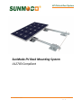
Grape Solar GS-12-PANEL-R-CMD Installation guide
- Type
- Installation guide

EZ Pitched Roof System
Pub. D10004-V016
Copyright 2017
SunModo PV Rack Mounting System
UL2703 Compliant

EZ Pitched Roof System
2 of 29
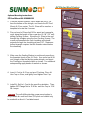
Please read carefully before installing
Product is tested to and recognized to UL 2703 standards for safety grounding and
bonding equipment and meets UL 1703 fire standards.
SunModo PV Rack Mount System can be used to mount photovoltaic (PV) panels in a
wide variety of locations. All installations shall be in accordance with NEC
requirements in the USA. The self-bonding system is for use with PV modules that
have a maximum series fuse rating of 30A. Mechanical design loads per UL 2703:
Downward Pressure: 33.42 psf (1600.2 Pa), Upward Pressure: 22.28 psf (1066.8 Pa),
Down-Slope: 5 psf (239.4 Pa).
TABLE OF CONTENTS
Installer Responsibility: .................................................................................................................... 4
Safety:.............................................................................................................................................. 4
Specifications: .................................................................................................................................. 4
Lag Pull-Out Capacities: .................................................................................................................. 5
SunModo Self-Grounding System .................................................................................................... 6
EZ Roof Mount System Components ............................................................................................... 7
List of Compliant PV Modules ........................................................................................................ 12
Tools Required for Installation ........................................................................................................ 15
Torque Values for Pitched Roof System ......................................................................................... 17
Flashing Placement:....................................................................................................................... 18
Sealant Application: ....................................................................................................................... 18
Installation Instructions: .................................................................................................................. 19
EZ Roof Mount Kit K10068-XXX ......................................................................................... 19
EZ Roof Mounting Standoff Kit K10070-XXX ...................................................................... 20
EZ Roof Mount with C-Bracket Kit K12005-001 .................................................................. 20
EZ Roof Mount Kit K10068-B20.......................................................................................... 21
EZ Metal Roof Mount Kit K20051-XXX ............................................................................... 22
EZ Metal Roof Mounting Standoff Kit K10064-XXX ............................................................ 23
EZ Metal Roof Mount with C-Bracket A22001-001.............................................................. 23
Portrait Panel Configuration: .......................................................................................................... 24
Minimum Panel Height ....................................................................................................... 25
End Clamp Attachment ....................................................................................................... 25
Mid Clamp Attachment ....................................................................................................... 25
Landscape Panel Configuration: .................................................................................................... 26

EZ Pitched Roof System
3 of 29
Minimum Panel Height ...................................................................................................... 27
End Clamp Attachment ....................................................................................................... 27
Mid Clamp Attachment ....................................................................................................... 27
Ground Wire Attachment ................................................................................................................ 28
Ground Lug Installation ...................................................................................................... 28
Rail End Covers ............................................................................................................................. 28
Document Number D10004-V016
©2017 – SunModo Corp.
File 0248
5001753

EZ Pitched Roof System
4 of 29
Installer Responsibility:
Before ordering and installing materials, all system layout dimensions should be confirmed by field measurements.
SunModo reserves the right to alter, without notice, any details, proposals or plans. Any inquiries that you may have
concerning installation of the PV system should be directed to your SunModo Sales representative. Consult
SunModo Sales for any information not contained in this manual. This manual is intended to be used as a guide
when installing SunModo’s EZ Roof Mount System on pitched roofs. It is the responsibility of the installer to ensure
the safe installation of this product as outline herein.
• Installer shall employ only SunModo products detail herein. The use of non SunModo components can
void the warranty and cancel the letters of UL compliance.
• Installer shall guarantee that screws and anchors have adequate pullout strength and shear capacities.
• Installer shall adhere to the torque values specified in this Instruction Manual.
• Installer shall use anti-seize compound, such as Permatex anti-seize, lubricant is recommended for all
threaded parts.
• Installer is responsible to install EZ Pitched Roof System over a Fire Resistant roof covering rated for the
application.
• Installer is responsible to determine that the roof, its rafters, connections, and other architectural support
components can sustain the array under all code level loading conditions.
• Installer shall adhere to all relevant local or national building codes. This takes account of those that
supplant this document’s requirements.
• Installer shall guarantee the safe placement of all electrical details of the PV array.
• Installer shall comply with all applicable local, state and national building codes, including periodic re-
inspection of the installation for loose components, loose fasteners and any corrosion, such that if found,
the affected components are to be immediately replaced.
• Installer to ensure the structural support members or footings for mounting the array can withstand all
code loading conditions. Consult with licensed professional engineer for the appropriate loading
conditions.
• Installer to follow all regional safety requirements during installation.
• This racking system may be used to ground and/or mount a PV module complying with UL 1703 only
when the specific module has been evaluated for grounding and/or mounting in compliance with the
included instructions.
Safety:
Review relevant OSHA and other safety standards before following these instructions. The installation of solar PV
systems is a dangerous procedure and should be supervised by trained and experienced personnel.
It is not possible for SunModo to be aware of all the possible job site situations that could cause an unsafe condition
to exist. The installer of the roof system is responsible for reading these instructions and determining the safest way
to install the roof system. These instructions are provided only as a guide to show a knowledgeable, trained erector
the correct part placement one to another. If following any of the installation steps would endanger a worker, the
erector should stop work and decide upon a corrective action. Provide required safety railing, netting, or safety lines
for crew members working on the roof.
Specifications:
EZ Roof Mount K10068 is certified for International Building Code and International Residential Codes (IRC) by
IAPMO. Evaluation Report is 0248, structural test per EC002-2011 and rain test per UL 441-96.

EZ Pitched Roof System
5 of 29
Lag Pull-Out Capacities:
Sources: American Wood Council, NDS 2005, Table 11.2 A, 11.3.2 A
Notes:
1) Actual test data in Southern Pine: Test Load at 0.250 inch deflection: 1,800 lbs. uplift (withdrawal); 240 lbs.
lateral. Test Load at 0.125 inch deflection: 695 lbs. uplift (withdrawal); 130 lbs. lateral.
2) Thread must be embedded in a rafter or other structural roof member.
3) See NDS Table 11.5.1 C for required edge distances.
Lag pull-out (withdrawal) capacities (lbs.) in typical lumber:
Specific
Gravity
5/16" Shaft
per 1" thread depth
5/16" Shaft
per 2-1/2" thread depth
Douglas Fir, Larch
.50
266
665
Douglas Fir, South
.46
235
588
Engelmann Spruce, Lodgepole Pine (MSR 1650 f & higher)
.46
235
588
Hem, Fir
.43
212
530
Hem, Fir (North)
.46
235
588
Southern Pine
.55
307
768
Spruce, Pine, Fir
.42
205
513
Spruce, Pine, Fir (E of 2 million psi and higher grades of MSR and MEL)
.50
266
665

EZ Pitched Roof System
6 of 29
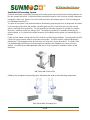
SunModo Self-Grounding System
SunModo developed a proprietary grounding and bonding system that is built into the mounting hardware for
the rails, clamps and splices. We provide further grounding through all of the SunBeam racking components
including the Pipe Caps, Beams, Posts and Post Base Plates. All hardware meet UL 2703 Grounding and
Fire Standards tested by ETL.
The basis of the system is our patented stainless steel floating grounding pin which is designed to be captive
in the mounting components and provides a bonding path from the PV panel frames to the rails and rail
splices, and finally to the ground lug. The self-grounding and bonding system is for use with PV modules
that have a maximum series fuse rating of 30A. The maximum number of PV modules is limited by the
system voltage, so in a system has multiple inverters, the SunModo racking system can theoretically go on
forever.
Finally we have added a spring and Blue 242 Loctite to our Mid Clamp assemblies. The sprig keeps the Mid
Clamp in the open position ready to receive the solar module. The Blue Loctite is a light bonding agent
allowing the T-Bolt engagement into the Rail when the Collar Nut is turned from above. The Blue Loctite
has the added benefit of being an anti-seize agent for stainless steel hardware in the area where it is
applied. For additional anti-seize protection refer to the ‘Tools Required for Installation’ section of this
document.
Mid Clamp with Ground Pins
Similarly, the rail splices the grounding pins, eliminating the need for extra bonding components.
Rail Splices with Grounding Pins

EZ Pitched Roof System
7 of 29
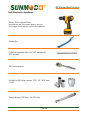
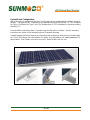
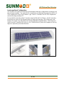
EZ Roof Mount System Components
Primary Materials
EZ Roof Mount Kit includes:
• Flashing
• L-Foot
• Roof Shoe and Gasket
• 4” Lag Bolt
• AL Hex Cap
• 3/8” Flange Nut and Bolt
K10068-XXX
EZ Roof Mount with L-Foot
(-001 as shown)
EZ Roof Mount Standoff Kit:
• Flashing
• L-Foot
• Roof Shoe and Gasket
• 4” Lag Bolt
• AL Hex Cap
• 3/8” Flange Nut and Bolt
• Standoff: 2” shown
K10070-XXX
EZ Roof Mount with Standoff
(Standoff heights: 2”, 3”, 5”
and 7”)
EZ Metal Roof Mount Kit includes:
• L-Foot
• Metal Roof Shoe and
Gasket
• 4” Lag Bolt
• AL Hex Cap
• 3/8” Flange Nut and Bolt
K10082-001
EZ Metal Roof Mount with L-
Foot
(as shown)
K20082-002
EZ Metal Roof Mount with L-
Tall Foot
Both are available in black
(-BK1 or BK2)
EZ Metal Roof Mount Standoff Kit:
• L-Foot
• Roof Shoe and Gasket
• 4” Lag Bolt
• AL Hex Cap
• 3/8” Flange Nut and Bolt
• Standoff: 2” shown
K10064-XXX
EZ Metal Roof Mount with
Standoff
(Standoff heights: 2”, 3”, 5”
and 7”)

EZ Pitched Roof System
8 of 29
Aluminum Flashings are offered in
two sizes: 10”X12.5” and 18”X18”.
Available in clear, black and
brown anodize.
A20052-XXX
AL Flashing
Aluminum L-Foot is offered in
clear, black and brown.
A20064-XXX
AL L-Foot
AL Hex Cap
Available in clear and black
A20066-001 and -BK1
AL Hex Cap
Aluminum Shoe is provided with
EPDM Sealing Washer installed.
A20065-001
AL Shoe
C10006-001
Sealing Washer
Aluminum Shoe (for metal roofs)
is provided with EPDM Sealing
Washer installed.
A20051-XXX
AL Shoe
C10007-001
Sealing Gasket
5/16 Stainless Steel Lag Bolts are
available lengths: 3.5”, 4”, 4.5”
and 5”
B15015-XXX
5/16 Stainless Steel Lag Bolt
OMG XHD (Extra Heavy Duty)
#15 Roofing Fastener
B15040-001 (4 reqd per
mount)
OMG 1/4 X 3" Decking Screw
XHD003B #15X3

EZ Pitched Roof System
9 of 29
Aluminum L-Foot available in
clear and black.
K10066-XXX
Standard L-Foot Kit
K10096-XXX
Tall L-Foot Kit
(3/8” Flange Nut and Bolt
included)
Aluminum Standoff heights: 2”, 3”,
5” and 7”
(part of EZ Roof Kit K10070-XXX)
A20049-XXX
Standoff (multiple lengths)
Helio Rails: Features both 1/4”
and 3/8” side slots, and 1/4” top
slot for clamping PV panels.
Available in 84”, 124”, 164” and
206” lengths. Last 3 digits denote
rail length. 4 stock sizes in clear
and black.
A20144-XXX (Clear)
A20144-XXX-BK (Black)
HR250 (Standard Rail)
A20145-XXX (Clear)
A20145-XXX-BK (Black)
HR350 (Heavy Rail)
A20146-XXX (Clear)
A20146-XXX-BK (Black)
HR500 (Super Rail)
Plastic Rail End Caps available
for Helio Standard and Heavy
rails (optional)
C10017-001 (Black)
C10017-001-GR (Gray)
HR250 (Standard Rail
C10021-001 (Black)
C10021-001-GR (Gray)
HR250 (Heavy Rail)
Metal Rail End Caps available for
Helio Standard and Heavy rails
(optional)
A20284-001
A20284-BK1 (Black)
HR250 (Helio Standard)
A20285-001
HR350 (Helio Heavy)
A20263-001
HR500 (Helio Super)
3/8” Slot Rail Splice Kit with 2X
3/8-16 hex bolts and flange nuts
with integral grounding.
May be repositioned until
torqued to final value.
K10178-001
HR250/HR350 3/8” Splice
For single-use only

EZ Pitched Roof System
10 of 29
1/4” Slot Rail Splice Kit with 4X
bolts and flange nuts with integral
grounding. May be repositioned
until torqued to final value.
K10177-001
K10177-BK1
HR250/HR350 1/4” Splice
For single-use only
K10250-001
K10250-001-BK
HR500 1/4” Splice
Requires bond jumper
End Clamp Kit, fits panel height
from 31 to 50 mm. For last 3
digits, see table on last page.
K10224-1XX
K10224-1XX-BK
Grounding Mid Clamp Kit fits panel
height from 31 to 50 mm. May be
repositioned until torqued to
final value.
K10180-001
K10180-001-BK
For single-use only
Grounding End Clamp Kit with
shared rail adaptor for standard
rail; fits panel height from 31 to 50
mm. For last 3 digits, see table on
last page. May be repositioned
until torqued to final value.
K10183-1XX
K10183-1XX-BK
For single-use only
Grounding Mid Clamp Kit with
shared rail adaptor for standard
rail; fits panel height from 31 to 50
mm. May be repositioned until
torqued to final value.
K10182-001
K10182-001-BK
For single-use only
Grounding Lug Kit with Grounding
Spacer and 1/4-20 T-Bolt. May be
repositioned until torqued to
final value.
K10179-001
For single-use only

EZ Pitched Roof System
11 of 29
HR150 (Open Rail): Features
wire management channel and
both 1/4” and 3/8” side slots, and
1/4” top slot for clamping PV
panels. Available in 84”, 124”,
164” and 206” lengths. Last 3
digits denote rail length. 4 stock
sizes in clear and black.
A20242-XXX (Clear)
A20242-XXX-BK (Black)
HR150 (Open Rail)
1/4” Slot Open Rail Splice Kit with
4X 1/4-20 Bolts and Flange Nuts
with integral grounding. May be
repositioned until torqued to
final value.
K10236-001
HR150 Splice Kit
For single-use only
Rail End Cap available for HR150
rails (optional)
A20250-001 (Clear)
A20250-BK1 (Black)
HR150 Rail End Cover
HR150 Channel Clip: snaps into
the open rail to manage wire
bundles where needed.
Available in clear and black.
A20252-001 (Clear)
A20252-BK1 (Black)
HR150 Wire Cover
The HR150 family of products are shown assembled above. Two HR150 Rails are
spliced together with an HR150 Rail Splice. PV electrical wires are shown routed in the
channels of the HR150 Rails, retained with two HR150 Channel Clips snapped into place.

EZ Pitched Roof System
12 of 29
List of Compliant PV Modules
UL 2703 Qualified Modules for use with SunModo PV Racking Systems
Evaluated PV Modules
Module
manufacturer
Model numbers
C-Sun
CSUN290-72P, CSUN295-72P, CSUN300-72P,
CSUN305-72P, CSUN310-72P, CSUN285-72M,
CSUN290-72M, CSUN295-72M, CSUN300-72M,
CSUN305-72M, CSUN310-72M, CSUN315-72M,
CSUN320-72M, CSUN235-60M, CSUN240-60M,
CSUN245-60M, CSUN240-60P, CSUN245-60P,
CSUN250-60P, CSUN255-60P, CSUN260-60P
Canadian Solar
CS6X-300P, CS6X-305P, CS6X-310P, CS6X-315P, CS6X-320P, CS6P-255P, CS6P-
260P, CS6P-265P, CS6P-260M, CS6P-265M, CS6V-210P, CS6V-215P, CS6V-220M,
CS6V-225M, CS6K-265M, CS6K-270M
ET Solar
ET-P672300WW, ET-P672305WW, ET-P672310WW, ET-P672315WW
Hanwha Q Cells
Q.PRO L-G2 305, Q.PRO L-G2 310, Q.PRO L-G2 315
Hareon
HR-280P-24/Ba, HR-285P-24/Ba, HR-290P-24/Ba, HR-295P-24/Ba,
HR-300P-24/Ba, HR-305P-24/Ba, HR-310P-24/Ba
Hyundai
HiS-M300TI, HiS-M305TI, HiS-M310TI, HiS-M315TI, HiS-M320TI, HiS-M325TI
HiS-S325TI, HiS-S330TI, HiS-S335TI, HiS-S340TI, HiS-S345TI, HiS-S350TI
Itek Energy
(50 mm frame)
IT250HE, IT255HE, IT260HE, IT265HE, IT270HE, IT275HE, IT280HE, IT285HE,
IT290HE, IT295HE, IT300HE, IT305HE, IT310HE
JA Solar
JAP6 72-300/3BB, JAP6 72-305/3BB, JAP6 72-310/3BB, JAP6 72-315/3BB, JAP6 72-
320/3BB
Kyocera
KD315GX-LFB, KU260-6MCA, KU265-6MCA, KD255GX-LFB2, KD260GX-LFB2,

EZ Pitched Roof System
13 of 29
LG
LG275S1C-G4, LG280S1C-G4, LG285S1C-G4, LG300N1C-G4, LG300N1K-G4,
LG305N1C-G4, LG310N1C-G4, LG315N1C-G4, LG320N1C-G4, LG335S2W-G4,
LG340S2W-G4, LG360N2W-B3, LG365N2W-B3, LG365N2W-G4, LG370N2W-G4,
LG375N2W-G4
Mitsubishi
PV-MLE270HD, PV-MLE275HD, PV-MLE280HD
Panasonic
VBHN285J40
Phono Solar Tech
PS255M-20/U, PS260M-20/U,
PS265M-20/U, PS270M-20/U,
PS275M-20/U, PS280M-20/U
PS300P-24T, PS305P-24T, PS310P-24T
PS315P-24T, PS320P-24T, PS325P-24T
Renesola
JC 255 M-24/Bbs, JC 260 M-24/Bbs, JC 265 M-24/Bbs, JC 270 M-24/Bbs,
JC 250 M-24/Bb, JC 255 M-24/Bb, JC 260 M-24/Bb,
JC 305 M-24/Abs, JC 310 M-24/Abs, JC 315 M-24/Abs, JC 320 M-24/Abs, JC 325 M-
24/Abs, JC 330 M-24/Abs, JC 335 M-24/Abs,
JC 330 S-24/Abs, JC 335 S-24/Abs, JC 340 S-24/Abs, JC 345 S-24/Abs,
JC 270 S-24/Bbs, JC 280 S-24/Bbs, JC 285 S-24/Bbs
Sanyo
HIP-190BA3, HIP-195BA3,
HIP-200BA3, HIP-205BA3,
HIT-N215A01, HIT-N220A01, HIT-N225A01
Silfab
SLA280M, SLA285M, SLA290M, SLA295M, SLA300M
SLG335M, SLG340M, SLG345M, SLG350M, SLG355M, SLG360M
SolarWorld
(V2.5 frame)
Sunmodule SW series:
SW 220 mono and poly,
SW 225 poly, SW 230 poly, SW 235 poly,
SW 240 mono and poly,
SW 245 mono and poly, SW 250 mono,
SW 255 mono, SW 260 mono, SW 265 mono, SW 270 mono
Sunmodule Plus series:
285W mono, 280W mono, 275W mono,
270W mono, 265W mono, 260W mono,
255W mono, 250W mono
Sunmodule Protect 275W mono
Sunmodule Protect 270W mono
Sunmodule Protect 265W mono
Sunmodule SW 245 - 255 poly / Pro-Series

EZ Pitched Roof System
14 of 29
SolarWorld
(33mm frame)
Sunmodule Pro-Series:
250W poly, 255W poly, 260W poly
315W XL mono, 320W XL mono,
325W XL mono,
Sunmodule Plus:
260W mono, 270W mono, 275W mono,
280W mono, 285W mono
Stion
STO-135A, STO-140A, STO-145A, STO-150A
SunEdison
F310EzD, F315EzD, F320EzD,
F325EzD, F330EzD, F335EzD,
F310EzC, F315EzC, F320EzC,
F325EzC, F330EzC, F335EzC,
R330EzC, R335EzC, R340EzC,
R345EzC, R350EzC, R355EzC
SunPower
X21-355-BLK, X21-345, SPR-E20-327,SPR-E19-320
Trina
TSM-225 PC/PA05, TSM-230 PC/PA05,
TSM-235 PC/PA05, TSM-240 PC/PA05,
TSM-245 PC/PA05
Yingli
YL230P-29b, YL235P-29b, YL240P-29b, YL245P-29b

EZ Pitched Roof System
15 of 29
Tools Required for Installation
Electric Drill or Impact Driver.
Note that the use of an impact driver is strongly
discouraged for all stainless nut and bolt hardware.
Roofing Bar
Drill Bit for lag bolts, pilot hole 7/32” diameter for
5/16” lag bolt
3/8” Socket wrench
Sockets for 3/8” drive sockets, 7/16”, 1/2”, 9/16” and
1-1/16”
Torque Wrench 3/8” drive, 0 to 35 ft. lbs.

EZ Pitched Roof System
16 of 29
Anti-seize compound (Permatex 80071 or
equivalent).
Caulk gun and silicon sealant
• ChemLink M1 (or equivalent) for wood and
composite roofs.
• ChemLink DuraLink (or equivalent) for metal
roofs.
Tape measure
Saws for cutting aluminum posts and rails as
necessary

EZ Pitched Roof System
17 of 29
Torque Values for Pitched Roof System
These values must be adhered to, both for mechanical strength and to insure the performance
of the integral grounding and bonding features. It is required that a torque wrench be used to
measure the bolt torque during final assembly, and it is recommended that anti-seize
compound be applied to the screw threads.
Hardware
Torque lbs.
1/4-20 Bolts and Hex Flange Nut
7.5 ft. lbs.
1/4-20 Ground Lug, Flange Nut with 7/16 Hex Head
7.5 ft. lbs.
1/4-20 Ground Lug, Setscrew with 1/8 Allen drive.
4.2 ft. lbs. (50 in. lbs.)
1/4-20 Mid or End Clamp, Female Standoff with 7/16”
Hex Head Collar Nut
7.5 ft. lbs.
5/16 Lag Bolts
25 ft. lbs.
3/8-16 Bolts and Hex Flange Nuts
15 ft. lbs.
3/8-16 T-Bolts and Hex Flange Nuts
15 ft. lbs.
1-1/16” Hex Cap
15 ft. lbs.

EZ Pitched Roof System
18 of 29
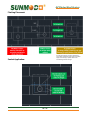
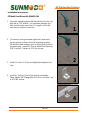
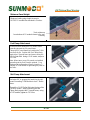
Flashing Placement:
Sealant Application:
If cutting the shingle to reposition the flashing
proves to be impractical, apply sealant around the
edges of the flashing to prevent debris from
accumulating under the shingle.

EZ Pitched Roof System
19 of 29
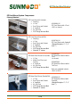
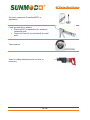
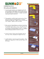
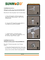
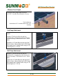
Installation Instructions:
EZ Roof Mount Kit K10068-XXX
1. From the marked location, move down the roof 2-1/4”
from the bottom of the shingle, and drill the pilot hole for
the Lag Bolt with a 7/32” drill bit. For maximum strength,
the hole should not be more than 3” in depth, and a drill
stop may be used to insure this.
2. Clean sawdust, and fill hole with sealant, such as Chem-
link M1 for wood and composite roofs, or ChemLink
DuraLink for metal roofs. Install AL Shoe to roof by using
5/16” Lag Bolt. Tighten to 25 ft. lbs. torque.
3. Make sure the Sealing Washer is positioned correctly on
the threaded shank of the AL Shoe. Use roofer bar to lift
roof shingle, slide the flashing under shingle, and insert
the Flashing on threaded shank as shown. For additional
waterproofing apply beads of sealant as shown.
4. Insert L-Foot to AL Shoe on top of Flashing. Place AL
Hex Cap on Shoe, and lightly hand tighten Hex Cap.
5. Install AL Rail to L-Foot to the specific orientation. Then,
tighten 3/8” Flange Nut to 15 ft-lbs. and Hex Cap to 15 ft-
lbs. torque.
2
3
4
5
1

EZ Pitched Roof System
20 of 29
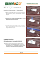
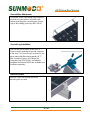
Installation Instructions:
EZ Roof Mounting Standoff Kit K10070-XXX
Installation Instructions:
EZ Roof Mount with C-Bracket Kit K12005-001
Mount the AL Shoe using steps 1-3 (shown above).
A. Place AL Standoff on AL Shoe threads and tighten
by hand, then by wrench. Use 15 ft.-lbs. nominal
torque.
B. Using the 3/8” Flange Bolt (supplied with AL L-Foot)
attach to the top of the Standoff.
C. Install AL Rail to L-Foot to the specific orientation.
Then, tighten 3/8” Flange Nut to 15 ft-lbs. and Hex
Cap to 15 ft-lbs. torque.
A
B
C
Mount the C-Bracket using steps 1-3 (shown above).
D. Mount the C-Bracket instead of an L-Foot, using
the Hex Nut. The C-Bracket can be used to mount
a variety of rails and other rooftop equipment.
D
Page is loading ...
Page is loading ...
Page is loading ...
Page is loading ...
Page is loading ...
Page is loading ...
Page is loading ...
Page is loading ...
Page is loading ...
-
 1
1
-
 2
2
-
 3
3
-
 4
4
-
 5
5
-
 6
6
-
 7
7
-
 8
8
-
 9
9
-
 10
10
-
 11
11
-
 12
12
-
 13
13
-
 14
14
-
 15
15
-
 16
16
-
 17
17
-
 18
18
-
 19
19
-
 20
20
-
 21
21
-
 22
22
-
 23
23
-
 24
24
-
 25
25
-
 26
26
-
 27
27
-
 28
28
-
 29
29


Grape Solar GS-12-PANEL-R-CMD Installation guide
- Type
- Installation guide
Ask a question and I''ll find the answer in the document
Finding information in a document is now easier with AI
Related papers
Other documents
-
 SunModo K10082-001 Operating instructions
-
Kmart 42280057 User manual
-
 Water-Tite 81715 Operating instructions
-
Smith Blair Inc 24500066306000 Installation guide
-
Ryobi 5133000214 Datasheet
-
 George Kovacs GKLR096-467 User manual
-
 George Kovacs GKST1004-084 User manual
-
George Kovacs GKST1006-084 User manual
-
-
Gibraltar Building Products 22999 Operating instructions


