Page is loading ...

INSTRUCTION MANUAL
COPYRIGHT © 2016 ALL RIGHTS RESERVED BY KING CANADA TOOLS INC.
MODEL: KFC-2TN
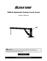
2 TON FOLDING SHOP CRANE
WITH DOUBLE PUMP
06/2016

WARRANTY INFORMATION
2-YEAR
LIMITED WARRANTY
FOR THIS SHOP CRANE
KING CANADA TOOLS
OFFERS A 2-YEAR LIMITED WARANTY
FOR NON-COMMERCIAL USE.
PROOF OF PURCHASE
Please keep your dated proof of purchase for warranty and servicing purposes.
REPLACEMENT PARTS
Replacement parts for this product are available at our authorized King Canada service centers across Canada.
LIMITED TOOL WARRANTY
King Canada makes every effort to ensure that this product meets high quality and durability standards. King Canada warrants to the
original retail consumer a 2-year limited warranty as of the date the product was purchased at retail and that each product is free from
defects in materials. Warranty does not apply to defects due directly or indirectly to misuse, abuse, normal wear and tear, negligence or
accidents, repairs done by an unauthorized service center, alterations and lack of maintenance. King Canada shall in no event be liable
for death, injuries to persons or property or for incidental, special or consequential damages arising from the use of our products.
To take advantage of this limited warranty, return the product at your expense together with your dated proof of purshase to an authorized
King Canada service center. Contact your retailer or visit our web site at www.kingcanada.com for an updated listing of our authorized
service centers. In cooperation with our authorized serviced center, King Canada will either repair or replace the product if any part or
parts covered under this warranty which examination proves to be defective in workmanship or material during the warranty period.
NOTE TO USER
This instruction manual is meant to serve as a guide only. Specifications and references are subject to change without prior notice.
PARTS DIAGRAM & PARTS LISTS
Refer to the Parts section of the King Canada web site for the most updated parts diagram and parts list.
KING CANADA INC. DORVAL, QUÉBEC, CANADA H9P 2Y4
www.kingcanada.com

SPECIFIC SAFETY INSTRUCTIONS
FOR SHOP CRANES
WARNING!
1. Study and understand all operating instructions before operating crane.
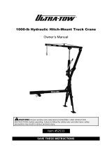
2. Do not exceed the rated capacity of the crane. Position 1 (.5 ton), position 2 (1 ton), position 3 (1.5 tons), position 4 (2 tons).
3. Make sure that the load is not allowed to drop suddenly or swing during transporting.
4. Make sure that boom is fully loaded (in its high position) before adding oil to unit reservoir.
5. This shop crane is designed for use only on hard, level surfaces capable of sustaining the load. Use on other than hard level surfaces can
result in shop crane instability and possible loss of load.
6. Slowly lower boom and load to the lowest possible position before transporting load.
7. Assemble crane according to the assembly instructions. Make sure all bolts and nuts are tight before placing crane into operation.
8. Do not use crane for any other purpose than for which it was designed and intended.
9. Crane legs must always extend beyond the boom.
10. Boom extension hardware must be secure before attempting to lift any load.
11. Never place any part of the body under the load or crane while in use.
12. Never use the crane as the only means of support. Always move the load to a stable platform or work surface before attempting any work.
13. Keep others away from the area while the crane is in operation.
14. Boom must be in fully lowered position before raising legs. Legs must never be raised when crane is carrying load. Legs must be locked
in place.
15. Before attempting to raise load, make sure it is securely fastened and safety latches are secure.
16. Do not operate crane with twisted or kinked chain.
17. Do not remove labels from crane.
18. Never use crane for lifting people or loads over people.
19. Do not remove ram and use separately for any purpose.
20. Never operate the crane under the influence of medication, drugs or alcohol.

FIGURE 1
SHOP CRANE CAPACITIES
CAPACITY
(TONS)
1/2 Ton
Position 1
1 Ton
Position 2
1-1/2 Tons
Position 3
2 Tons
Position 4
BOOM
HEIGHT
BOOM
LENGTH
62-1/4”
55-
1/8”
48”
41”
REACH
45-1/4”
38-1/8”
31-1/8”
24”
WHEEL
DIAMETER
3-1/2”
3-1/2”
3-1/2”
3-1/2”
CHAIN
SIZE
3/8 x 12
3/8 x 12
3/8 x 12
3/8 x 12
NET
WEIGHT
(LBS)
205 lbs.
205 lbs.
205 lbs.
205 lbs.
OVERALL
HEIGHT
58-5/8”
58-5/8”
58-5/8”
58-5/8”
BASE
LENGTH
BASE
WIDTH
(OUTSIDE)
LENGTH
INSIDE
LEGS
MAX
100-
3/8”
95-
5/8”
94-
1/8”
85-
7/8
”
MAX
65”
65”
65”
65”
MIN
20-5/8”
20-5/8”
20-5/8”
20-5/8”
MAX
34-5/8”
34-5/8”
34-5/8”
34-5/8”
MIN
31-7/8”
31-7/8”
31-7/8”
31-7/8”
MAX
47-5/8”
47-5/8”
47-5/8”
47-5/8”
MAX
47-5/8”
47-5/8”
47-5/8”
47-5/8”
MIN
3”
9 -
1/4”
15 -
3/8”
21-
1/2”

ASSEMBLY & OPERATION
ASSEMBLY
Note: Refer to parts diagram for index numbers found in parenthesis (#):
1. Install two wheels (#37) to the front legs (#47) and two wheels (#37) to the frame base (#32) using four M8 x 20 hex. bolts (#36), washers (#35),
spring washers (#34) and hex. nuts (#33). Install two wheels (#41) to the frame base (#32) using four M8 x 12 hex. bolts (#44), washers (#42)
and spring washers (#43).
2. Attach front legs (#47) to the frame base (#32) using all four hitch pins (#39) and hitch pin clips (#40). On each leg, insert 1 pin through frame
base and front leg at rear hole. The hitch pin serves as a pivot pin and remains in the hole permanently. Insert a second hitch pin in the most
forward hole through the frame base and front leg. This locks the legs in the down position.
3. Insert hitch pin clips (#40) through hitch pins (#39) to secure in place.
4. Attach the main support post (#22) to the frame base (#32) using two M16 x 100 hex. bolts (#28), washers (#45) and hex. nuts (#46).
5. Attach both support straps (#21) to the top of the main support post (#22) using M16 x 110 hex. bolt (#18), washers (#19) and hex. nuts (#20).
6. Connect the support straps (#21) to the frame base (#32) using two M16 x 100 hex. bolts (#38), washers (#30) and hex. nuts (#29).
7. Connect the bottom of the hydraulic ram assembly (#23) to the main support post (#22) using a M16 x 90 hex. bolt (#27), washer (#25), spring
washer (#26), and hex. nut (#24).
8. Connect the boom (#1) to the main support post (#22) using a M16 x 120 hex. bolt (#17), washer (#16) and hex. nut (#15).
9. While another person supports the boom (#1) up attach the top of the hydraulic ram assembly (#23) to the boom with a M16 x 80 hex. bolt (#5),
washer (#4), spring washer (#3) and hex. nut (#2).
10. Slide the boom extension (#9) into the boom (#1) with the slot for the hook and chain assembly (#14) facing down.
11. Install chain and hook assembly (#14) using a M12 x 80 hex. bolt (#13), washer (#12), spring washer (#11) and hex. nut (#10).
12. Install handle assembly (#49) to the rear of the support post (#22) using two M8 x 20 hex. bolts (#52), washers (#51) and spring washers
(#50).
13. Install all four end caps (#53).
14. Make sure all hardware is tight.
OPERATION
1. Load to be lifted must be securely attached with a sling or chain of adequate size and strength. Before lifting the load, be sure the load cannot
twist or fall.
2. Move crane into position. Legs must be in down position and locked into place. Never use crane with the legs in the upright position.
3. Close hydraulic valve at the base of ram by turning clockwise until tight.
4. Place sling or chain in center of hook.
5. Slowly raise the load to desired height by inserting ram handle and pumping handle.
6. Move load to desired location by rolling crane assembly. Use caution so that load does not swing or rotate.
7. Slowly lower load to desired location by inserting ram handle onto valve at base of the ram and slowly turning counterclockwise. Do not lower
too quickly. Make sure the load is secure once lowered fully.
/