Page is loading ...

20 TON HYDRAULIC SHOP PRESS
WITH GRID GUARD
INSTRUCTION MANUAL
COPYRIGHT © 2019 ALL RIGHTS RESERVED BY KING CANADA TOOLS INC.
MODEL: KHP-20T-GGN

WARRANTY INFORMATION
2-YEAR
LIMITED WARRANTY
FOR THIS HYDRAULIC PRESS
KING CANADA TOOLS
OFFERS A 2-YEAR LIMITED WARANTY
FOR NON-COMMERCIAL USE.
PROOF OF PURCHASE
Please keep your dated proof of purchase for warranty and servicing purposes.
REPLACEMENT PARTS
Replacement parts for this product are available at our authorized King Canada service centers across Canada. Please use the 10 digit
part numbers listed in this manual for all part orders where applicable.
LIMITED TOOL WARRANTY
King Canada makes every effort to ensure that this product meets high quality and durability standards. King Canada warrants to the
original retail consumer a 2-year limited warranty as of the date the product was purchased at retail and that each product is free from
defects in materials. Warranty does not apply to defects due directly or indirectly to misuse, abuse, normal wear and tear, negligence
or accidents, repairs done by an unauthorized service center, alterations and lack of maintenance. King Canada shall in no event be
liable for death, injuries to persons or property or for incidental, special or consequential damages arising from the use of our products.
To take advantage of this limited warranty, return the product at your expense together with your dated proof of purchase to an
authorized King Canada service center. Contact your retailer or visit our web site at www.kingcanada.com for an updated listing of our
authorized service centers. In cooperation with our authorized service center, King Canada will either repair or replace the product if
any part or parts covered under this warranty which examination proves to be defective in workmanship or material during the
warranty period.
NOTE TO USER
This instruction manual is meant to serve as a guide only. Specifications and references are subject to change without prior notice.
KING CANADA INC. DORVAL, QUÉBEC, CANADA H9P 2Y4
www.kingcanada.com

GENERAL & SPECIFIC
SAFETY INSTRUCTIONS
GENERAL SAFETY RULES
1. KNOW YOUR TOOL
Read and understand the owners manual and labels affixed to
the tool. Learn its application and limitations as well as its
specific potential hazards.
2. KEEP WORK AREA CLEAN.
Cluttered areas and benches invite accidents. Make sure the
floor is clean and not slippery.
3. AVOID DANGEROUS ENVIRONMENT.
Don’t use in damp or wet locations or expose them to rain. Keep
work area well lit and provide adequate surrounding work space.
4. KEEP CHILDREN AWAY.
All visitors should be kept a safe distance from work area.
5. USE RIGHT TOOL.
Don’t force the tool or the attachment to do a job for which it was
not designed.
6. WEAR PROPER APPAREL.
Do not wear loose clothing, gloves, neckties or jewelry (rings,
watch) because they could get caught in moving parts. Non-slip
footwear is recommended. Wear protective hair covering to
contain long hair. Roll up long sleeves above the elbows.
7. ALWAYS WEAR SAFETY GLASSES.
Always wear safety glasses (ANSI Z87.1). Everyday eye-glasses
only have impact resistant lenses, thet are NOT safety glasses.
8. DON’T OVERREACH.
Keep proper footing and balance at all times.
9. MAINTAIN TOOL WITH CARE.
Keep tools clean for best and safest performance. Follow
instructions for lubricating and changing accessories.
10. USE RECOMMENDED ACCESSORIES.
Consult the manual for recommended accessories. Follow the
instructions that accompany the accessories. The use of
improper accessories may cause hazards.
11. NEVER STAND ON TOOL.
Serious injury could occur if the tool tips over. Do not store
materials such that it is necessary to stand on the tool to reach
them.
12. CHECK DAMAGED PARTS.
Before further use of the tool, a guard or other parts that are
damaged should be carefully checked to ensure that they will
operate properly and perform their intended function. Check for
alignment of moving parts, breakage of parts, mounting, and
any other conditions that may affect its operation. A guard or
other parts that are damaged should be properly repaired or
replaced.
SPECIFIC SAFETY RULES FOR HYDRAULIC SHOP
PRESS
1. RATED CAPACITY.
Maximum load is 20 Tons. DO NOT exceed this rated capacity.
Always use the pressure gauge to accurately determine the
applied load.
2. QUALIFIED PERSON.
Only a qualified person should maintain this press. Keep it clean
for best and safest performance.
3. PROTECT YOURSELF.
Wear ANSI safety glasses or a full-face impact shield along with
heavy-duty gloves when operating press.
4. WORK PLACE.
Use this press on a stable, level, dry surface capable of
sustaining the load.
5. INSPECT BEFORE USE.
Inspect the press before each use. DO NOT use if bent, broken,
cracked, leaking or otherwise damaged.
6. TIGHTEN HARDWARE.
Make sure all bolts and nuts are firmly tightened before use.
7. KEEP HANDS AWAY.
Keep your hands away from the bed at all times during use.
8. DO NOT COMPRESS SPRINGS.
Never attempt to compress springs or any other item that could
disengage and cause a potential hazard. Never stand directly in
front of loaded press and never leave unattended.
9. USE PROPER HYDRAULIC OIL.
DO NOT use brake fluid or any other type of improper fluid,
avoid mixing different types of oil when adding hydraulic oil. Only
good quality hydraulic pump oil can be used.
10. CENTER WORKPIECE.
Make sure that the workpiece is center-loaded and secure.
11. GRID GUARD.
Always position the grid guard before all operations.

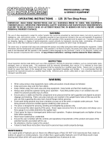
GETTING TO KNOW YOUR
20 TON HYDRAULIC PRESS
1. Pressure gauge. Indicates the applied pressure in tons.
2. Hydraulic cylinder.
3. Hydraulic cylinder ram and hub. Position your workpiece
centered under the hub.
4. Pressure plates (2).
5. Height adjustable bed frame.
6. Bed frame posts (2).
7. Hydraulic pump.
8. Hydraulic pump release valve.
9. Hydraulic pump handle.
10. Hydraulic pump oil filler nut.
11. Grid guard.
MODEL KHP-20T-GGN
Maximum capacity
20 Ton
Stroke 6-1/4”
Working range 0 - 40”
Bed width 21-3/8”
Bed depth 8-1/4”
Dimensions (LxWxH) 32” x 27-1/2” x 69-3/8”
Weight 210 lbs

ASSEMBLY, OPERATION
AND MAINTENANCE
ASSEMBLY- Refer to the parts diagram in this manual as a guide to assemble this hydraulic shop press.
1) Attach together one base section (#223) and lower cross bar (#228) to the left post (#221) using hex. bolts (#227), washers (#224), spring
washers (#225) and hex. nuts (#226). Only hand tighten the hardware at this point. Then attach the other base section and the lower cross bar
to the right post.
2) Attach four diagonal braces (#222) to the outside of the base sections and posts using hex. bolts (#227), washers (#224), spring washers
(#225) and hex. nuts (#226).
3) Tighten all hardware firmly in steps 1 and 2. Place the assembled frame in its upright position.
4) This next step normally requires another person to help you. Both upper cross beams (#210) and cylinder under plate (#207) must be placed
together so the under plate brackets suspend it from the upper cross beams. One person must lift and position these parts on the top of the
posts, the second person must insert four hex. bolts (#209) throught the upper cross beams and posts to hold it in place. Fix these parts to the
posts using washers (#211), spring washers (#212) and hex. nuts (#213). At this point the under plate should hang from the upper cross beams.
5) Screw the upper round nut (#206) onto the cylinder body (#203). Insert the cylinder into the opening in the under plate (#207), then screw the
under round nut (#208) onto the cylinder from underneath the under plate. Install the hub (#205) to the bottom of the cylinder ram and secure
it in place with the set screw (#204).
6) Insert both bed frame support pins (#220) into the frame posts (equal height). Position the two bed frames (#218 & 219) onto the two bed frame
support rods. Attach both bed frames together by inserting four long hex. bolts (#229) through bed frame, then bushings (#230) then the bed
frames again, fix using washers (#214) and hex. nuts (#215).
7) Install the pump plate (#233) to the right side frame post using hex. bolts (#227), washers (#224), spring washers (#225) and hex. nuts (#226).
Then install the hydraulic pump assembly (#234) to the pump plate using hex. bolts (#231) and washers (#232). Screw in the pump handle
and grip (#235).
8) Connect the hydraulic hose (#236) to the connection nut on the cylinder, then install the pressure gauge (#201) to the pressure gauge
connection nut.
9) Install grid guard sliding brackets (#237) to the front bed frame (#219) using hex. nuts (#226). Slide the grid guard (#238) in between the sliding
brackets and lock it in place by installing and tightening lock knobs (#239).
BEFORE USING FOR THE FIRST TIME
1) Before using this hydraulic shop press for the first time, purge away air from the hydraulic system, open the release valve (A) Fig.1
by turning it counterclockwise. Pump several full strokes to eliminate the air in the system, retighten release valve.
2) Check all parts, if there are any broken parts, do not use this hydraulic shop press until the broken parts have been replaced.
OPERATION
1) Position the bed frame to the appropriate height using the bed frame posts. Place the
pressure plates (#217) on the bed frame and then position your workpiece in between
them.
2) Close the hydraulic pump release valve (A) Fig.1 by turning it clockwise until it is firmly
closed.
3) Pump the pump handle until the hub gets near the top of the workpiece.
4) Align the workpiece or the entire cylinder assembly to ensure center-loading.
5) Lift the grid guard and lock into place by tightening the two lock knobs.
6) Pump the pump handle to apply load onto workpiece.
7) When the work is done, stop pumping pump handle, slowly remove the load from
workpiece by turning the pump release valve counterclockwise in small increments.
8) Once the ram has completely retracted, lower the grid guard and remove your workpiece
from the bed frame.
MAINTENANCE
1) Clean the outside of the press with a dry cloth and periodically lubricate the joints and all moving parts with a light oil as needed.
2) When not in use, store the hydraulic shop press in a dry location with the ram and piston of the cylinder fully retracted.
3) When the press effeciency drops, purge the hydraulic system to eliminate any air in the system.
4) Check hydraulic oil: remove the oil filler nut (B) Fig.1 on the pump, if hydraulic oil is needed, fill with high quality hydraulic pump oil as
necessary. Replace the oil filler nut and purge away any air from the hydraulic system.
FIGURE 1

PARTS DIAGRAM
MODEL KHP-20T-GGN
PARTS DIAGRAM & PARTS LISTS
Refer to the Parts section of the King Canada web site for the most updated parts diagram and parts list.
/