Page is loading ...

Rev. 1/23/2018 WTJ-2, MANUAL
Copyright 2018 Vestil Manufacturing Corp. Page 1 of 12
WTJ-2 Series Vehicle Mounted Jib Cranes
Instruction Manual
Receiving instructions:
After delivery, remove the packaging from the product. Inspect the product closely to determine whether
it sustained damage during transport. If damage is discovered, record a complete description of it on the
bill of lading. If the product is undamaged, discard the packaging.
NOTE:
The end-user is solely responsible for confirming that product design, installation, use, and maintenance
comply with laws, regulations, codes, and mandatory standards applied where the product is used.
Table of Contents
Specifications……….……………………………………………..……………………………………………….. 2
WTJ-2 Exploded Parts Diagram………………………………………...………………………………………... 3
Bills of Materials (WTJ-2 & WTJ-G)……………..……………………………………………………..………… 4
WTJ-2-G & WTJ-2-SS Exploded Parts Diagram……………………………………………………………….. 5
Bill of Materials (WTJ-2-SS)………………………………………………………………………………………. 6
Assembling the Crane…………………………………………………………………………………….…….…. 6
Signal words………………………………………………………………………………………………..………. 7
Hazards of improper use………………………………………………………………..……………………..….. 7
Installing the Crane in a Fixed Location (not in a Vehicle)...……………………………………………..……. 8
Installing the Crane on a Vehicle………………………………………………………………………….……… 8
Raising and Lowering the Boom…………………………………………………………………………..……… 9
Boom Length Adjustments……………………………………………………………………………..…………. 9
Using the crane………………………………………………………………………………………….…………. 9-10
Inspections………………….………………………………………………………………………………………. 10
Troubleshooting………………………………………...…………………………………................................... 11
Labeling Diagram……………………………….…………..……………………………………………………… 11
Limited Warranty………………………………………..………………………………………………………….. 12
Vestil Manufacturing Co.
2999 North Wayne Street, P.O. Box 507, Angola, IN 46703
Telephone: (260) 665-7586 -or- Toll Free (800) 348-0868
Fax: (260) 665-1339
Web: www.vestilmfg.com e-mail:

Rev. 1/23/2018 WTJ-2, MANUAL
Copyright 2018 Vestil Manufacturing Corp. Page 2 of 12
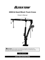
Specifications:
Crane dimensions, capacity, and net weight appear in the diagram and table below. All figures are subject to change
without notice.
WTJ-2
WTJ-2-G & WTJ-2-SS
Mounting plate dimensions
Fixed hook
Winch hook
Fixed hook capacities:
Boom extended (“long”) = 500 lb. (227.3kg)
Boom retracted (“short”) = 1,000 lb. (454.5kg)
Winch & winch hook capacity = 500 lb. (227.3kg)
Winch hook heights:
Cylinder extended & boom extended = 102” (259cm)
Cylinder extended & boom retracted = 89
1
/
2
” (227cm)
Cylinder retracted & boom extended = 0” (0cm)
Cylinder retracted & boom retracted = 10” (25cm)
Cable dimensions:
Overall length = 14
1
/
2
ft. (4.4m)
Usable length = 9 ft. (2.7m)
Usable reach:
Boom horizontal & extended = 54” (137cm))
Boom horizontal & retracted = 30
1
/
4
” (77cm)
NNet weight of crane = 135 lb. (61.4kg)
3D model
shown for
reference
Fixed hook capacities:
Boom extended (“long”) = 500 lb. (227.3kg)
Boom retracted (“short”) = 1,000 lb. (454.5kg)
Winch & winch hook capacity = 500 lb. (227.3kg)
Winch hook heights:
Cylinder extended & boom extended = 99” (39cm)
Cylinder extended & boom retracted = 84” (33cm)
Cylinder retracted & boom extended = 0” (0cm)
Cylinder retracted & boom retracted = 12
1
/
2
” (32cm)
Cable dimensions:
Overall length = 32 ft. (9.8m)
Usable length = 24 ft. (7.3m)
Usable reach:
Boom horizontal & fully extended = 52” (132cm)
Boom horizontal & fully retracted = 30
1
/
2
” (78cm)
Net weight of crane = 134 lb. (61kg)
Mounting plate dimensions
Fixed hook
Winch hook

Rev. 1/23/2018 WTJ-2, MANUAL
Copyright 2018 Vestil Manufacturing Corp. Page 3 of 12
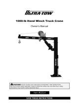
WTJ-2 Exploded Parts Diagram (Bill of Materials on p. 4)
5
B (“long boom”
configuration)
A (“short boom”
configuration)
Boom
configuration
Fixed hook
capacity
Winch hook
capacity
A (short boom) 1,000 lb. (kg) 500 lb.
B (long boom) 500 lb. (kg) 500 lb.
Cable clamp (18)
U
-
bolt
Saddle
Hex
nut
Winch hook (19) installation
Dead
end
side of
cable
Hex
nut
Saddle
U-bolt

Rev. 1/23/2018 WTJ-2, MANUAL
Copyright 2018 Vestil Manufacturing Corp. Page 4 of 12
Item
Part no. Description Qty.
Item
Part no. Description Qty.
1 WTJ-2-11-1 Winch without handle 1 26 WTJ-2-11-26
Bolt, hex head, M16-2.0x90 1
2 WTJ-2-11-2 Cable, winch 1 27 WTJ-2-11-27
Bolt, hex head, M12-1.75x40 6
3 WTJ-2-11-3 Bushing (not used after 2010) 1 28 WTJ-2-11-28
Turntable 1
4 WTJ-2-11-4 Pulley, large 1 29 WTJ-2-11-29
Bearing, tapered ball with race
1
5 WTJ-2-11-5 Post, main (“mast”) 1 30 WTJ-2-11-30
Cup, bearing 1
6 WTJ-2-11-6 Nut, hex, M14 2 31 WTJ-2-11-31
Zerk, grease 1
7 WTJ-2-11-7 Washer, lock, M14 2 32 WTJ-2-11-32
Base without hardware 1
8 WTJ-2-11-8 Washer, flat, M14 2 33 WTJ-2-11-33
Knob, locking handle 1
9 WTJ-2-11-9 Boom, outer 1 34 WTJ-2-11-34
Bolt, turntable locking 1
10 WTJ-2-11-10 Pin with chain and hitch clip 1 35 WTJ-2-11-35
Handle, swivel 1
11 WTJ-2-11-11 Boom, telescoping 1 36 WTJ-2-11-36
Grip, handle 2
12 WTJ-2-11-12 Bolt, hex head, M10-1.5x80 1 37 WTJ-2-11-37
Bolt, hex head, M10-
1.5x20mm
2
13 WTJ-2-11-13 Nut, hex, M12 6 38 WTJ-2-11-38
Washer, lock, M10 2
14 WTJ-2-11-14 Washer, lock, M12 6 39 WTJ-2-11-39
Washer, flat, M10 2
15 WTJ-2-11-15 Washer, flat, M12x24mm 6 40 WTJ-2-11-40
R pin, M3 1
16 WTJ-2-11-16 Pulley, small 1 41 WTJ-2-11-41
Bearing, ball, 6202-ZZ 1
17 WTJ-2-11-17 Bearing, ball 1 42 WTJ-2-11-42
Bolt, special shouldered 1
18 WTJ-2-11-18 Clamp, wire,
1
/
4
” 2 43 WTJ-2-11-43
Bushing 1
19 WTJ-2-11-19 Hook, retractable/winch 1 44 WTJ-2-11-44
Pin, M12x40 1
20 WTJ-2-11-20 Hook, fixed 1 45 WTJ-2-11-45
Pin, cotter, M2x25 1
21 WTJ-2-11-21 Bolt, hex head, M16-2.0x90 1 46 WTJ-2-11-46
Nut, hex, M10 1
22 WTJ-2-11-22 Nut, hex, M16 2 47 WTJ-2-11-47
Bolt, hex head, M8-1.25x25 1
23 WTJ-2-11-23 Washer, lock, M16 2 48 WTJ-2-11-48
Washer, flat, M8 1
24 WTJ-2-11-24 Washer, flat, M16 2 49 WTJ-2-11-49
Handle, winch 1
25
WTJ-2-11-25
WTJ-2-11-25A
Jack, hydraulic, 3-ton
Handle, jack
1
WTJ
-
2 Bill of Materials
(see Exploded Parts D
iagram on p. 3)
:
Item
Part no. Description Qty.
Item
Part no. Description Qty.
1 WTJ-2-G-1 Winch without handle 1 23 WTJ-2-G-23
Washer, lock, M16 3
2 WTJ-2-G-2 Cable, winch 1 24 WTJ-2-G-24
Washer, flat, M16 3
3 WTJ-2-G-3 Bushing (not used after 2010) 1 25 WTJ-2-G-25
Jack, hydraulic, 3-ton 1
4 WTJ-2-G-4 Pulley, large 1 26 WTJ-2-G-26
Bolt, hex head, M16-2.0x90 1
5 WTJ-2-G-5 Post, main (“mast”) 1 27 WTJ-2-G-27
Bolt, hex head, M12-1.75x40 6
6 WTJ-2-G-6 Nut, Nylon, lock, M14 1 28 WTJ-2-G-28
Turntable 1
7 WTJ-2-G-7 Washer, lock, M14 1 29 WTJ-2-G-29
Bearing, tapered ball 1
8 WTJ-2-G-8 Washer, flat, M14 1 30 WTJ-2-G-30
Sleeve, bearing 1
9 WTJ-2-G-9 Boom, outer 1 31 WTJ-2-G-31
Zerk, grease 1
10 WTJ-2-G-10
Bolt, hex head, M14-
2.0x100mm
1 32 WTJ-2-G-32
Base without hardware 1
11 WTJ-2-G-11
Boom, telescoping 1 *33 WTJ-2-G-33
Knob, locking handle 1
12 WTJ-2-G-12
Bolt, hex head, M10-1.75x85 1 34 WTJ-2-G-34
Bolt, turntable locking 1
13 WTJ-2-G-13
Nut, Nylon, lock M12 7 35 WTJ-2-G-35
Handle, swivel 1
14 WTJ-2-G-14
Washer, lock, M12 7 *36 WTJ-2-G-36
Grip, handle 1
15 WTJ-2-G-15
Washer, flat, M12x24mm 7 37 WTJ-2-G-37
Bolt, hex head, M10-
1.5x20mm
3
16 WTJ-2-G-16
Pulley, small with bearing 1 38 WTJ-2-G-38
Washer, lock, M10 3
17 WTJ-2-G-17
Bearing, ball, 6201-RS 1 39 WTJ-2-G-39
Washer, flat, M10 3
18 WTJ-2-G-18
Clamp, wire,
1
/
4
” 2 40 WTJ-2-G-40
Hitch pin, M3 1
19 WTJ-2-G-19
Hook, retractable/winch 1 41 WTJ-2-G-41
Bearing, ball, 6202-ZZ 1
20 WTJ-2-G-20
Hook, fixed, with chain 1 42 WTJ-2-G-42
Bolt, special shouldered 1
21 WTJ-2-G-21
Bolt, hex head, M16-2.0x90 1 43 WTJ-2-G-43
Bushing 1
22 WTJ-2-G-22
Nut, Nylon, lock, M16 3 44 WTJ-2-G-44
Handle, pump 1
*Knob might be molded to end of locking bolt (34).
**Grip might already be installed on mast handle (35).
WTJ
-
2
-
G Bill of Materials
(see
Exploded Parts Diagram on p. 5)
:

Rev. 1/23/2018 WTJ-2, MANUAL
Copyright 2018 Vestil Manufacturing Corp. Page 5 of 12
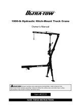
WTJ-2-G & WTJ-2-SS Exploded Parts Diagram (Bill of Materials on p. 4)
B (“long boom”
configuration)
A (“short boom”
configuration)
Boom
configuration
Fixed hook
capacity
Winch hook
capacity
A (short boom)
2,000 lb.
(909.1 kg)
500 lb.
(227.3 kg)
B (long boom)
1,000 lb.
(454.5 kg)
500 lb.
(227.3 kg)
Cable clamp (18)
U
-
bolt
Saddle
Hex
nut
Winch hook (19) installation
Dead
end
side of
cable
Hex
nut
Saddle
U-bolt
Handle
socket

Rev. 1/23/2018 WTJ-2, MANUAL
Copyright 2018 Vestil Manufacturing Corp. Page 6 of 12
WTJ-2-SS Bill of Materials (see Exploded Parts Diagram on p. 5)
Assembling the Crane:
Refer to the exploded parts diagram for your crane (either on p. 3 or on p. 5) and the corresponding bill of materials.
Numbers in parentheses () correspond to item numbers in the diagrams.
1) As shipped, the receiver (32), turntable locking knob and bolt (33 & 34), bearing cup (30), tapered roller bearing (29),
bushing (43), and turntable (28) are assembled.
2) Fasten the mast (5) to the turntable with M12x40mm bolts (27) and corresponding flat washers (15), lock washers (14),
and hex nuts (13). Fasten the mast to the turntable with 6 sets of fasteners (27, 15, 14, and 13). Insert bolts upwards
through the bolt holes.
3) Attach the boom (9) and large pulley (4) to the top of the mast. Position the end of the boom inside the top of the mast
and align bolt holes. Insert the M14 shoulder bolt (42; the bolt has a wide shoulder and a narrow shoulder) through the
bolt holes on one side. Slide the large pulley (4) onto the free end of the bolt; then insert the bolt through the other side
of the boom and mast. Secure it with an M14 flat washer (8), lock washer (7), and hex nut (6).
4) Attach the pump (25) to the crane. First, attach the base of the pump to the mast using the M16x90mm hex bolt (26).
The bolt is approximately 3.5 inches long. Secure the bolt with an M16 flat washer (24), lock washer (23), and hex nut
(22). Next, attach the pump plunger/piston to the underside of the boom with the M16x80mm hex bolt (21). The bolt is
just a bit longer than 3 inches. Secure the bolt with an M16 flat washer (24), lock washer (23), and hex nut (22).
5) Slide the telescoping boom (11) into the boom. Fasten the booms together with an M14x100mm hex bolt (10) at either
location A or location B. Install an M14 flat washer (8), lock washer (7), and hex nut (6).
NOTE: Instead of an M14x100 bolt, washers and nut, your hardware kit might include a clevis pin (with chain) and a
hitch pin. Slide the clevis pin through the holes. Secure it with the hitch pin.
6) Attach the winch (1) to the bracket on the back of the mast with two M10x20mm hex bolts (37). Secure each bolt with
an M14 flat washer (39) and lock washer (38).
7) Connect the winch handle (49) to the winch with an M8 flat washer (48; washer is thicker than an ordinary flat washer)
and M8x25mm hex bolt (~1inch long).
8) Install the small pulley (16) in the free end of the telescoping boom. Bearing (17) is already installed in the center of the
pulley. Align the hole in the pulley with the bolt holes in the end of the boom and insert an M10x80mm hex bolt (12)
through the holes. Secure the free end with an M10 flat washer (39), lock washer (38), and hex nut (46).
9) Turn the winch handle counterclockwise to unwind cable. Unwind approximately 8 feet of cable. Feed the end of the
cable over the groove in the top of the big pulley and through the boom, the telescoping boom and into the groove on
top of the small pulley. Look at the underside of the telescoping boom. There is a rectangular slot near the end below
the small pulley. Feed the end of the cable through the slot from the inside of the boom.
10) Attach the winch hook (19) to the end of the cable. Feed 4-6 inches of cable through the circular eyelet in the top of
the hook. Install cable clamps as shown in the “Winch hook installation” diagram on p. 3 or p. 5. Insert the U-bolts from
the dead end side of the cable; then install the saddle and hex nuts. Securely tighten the nuts.
11) Lift a test weight with the fixed hook equal to 125% of the rated capacity (1,250 lb.). Inspect the crane and the
installation site after performing the load test. Look for cracks, warps, and other forms of damage at and around the
installation site. Repair the site if necessary. Perform another load test to confirm that problems are resolved.
Item
Part no. Description Qty.
Item Part no. Description Qty.
1 WTJ-2-SS-1 Winch without handle
1
23 WTJ-2-G-23 Washer, lock, M16
3
2 WTJ-2-SS-2 Cable, winch
1
24 WTJ-2-G-24 Washer, flat, M16
3
3 WTJ-2-SS-3 Bushing (not used after 2010)
1
25 WTJ-2-G-25 Jack, hydraulic, 3-ton
1
4 WTJ-2-SS-4 Pulley, large
1
26 WTJ-2-G-26 Bolt, hex head, M16-2.0x90
1
5 WTJ-2-SS-5 Post, main (“mast”)
1
27 WTJ-2-G-27 Bolt, hex head, M12-1.75x40
6
6 WTJ-2-SS-6 Nut, Nylon, lock, M14
1
28 WTJ-2-G-28 Turntable
1
7 WTJ-2-SS-7 Washer, lock, M14
1
29 WTJ-2-G-29 Bearing, tapered ball
1
8 WTJ-2-SS-8 Washer, flat, M14
1
30 WTJ-2-G-30 Sleeve, bearing
1
9 WTJ-2-SS-9 Boom, outer
1
31 WTJ-2-G-31 Zerk, grease
1
10 WTJ-2-SS-10
Bolt, hex head, M14-2.0x100mm
1
32 WTJ-2-G-32 Base without hardware
1
11 WTJ-2-SS-11
Boom, telescoping
1
*33 WTJ-2-G-33 Knob, locking handle
1
12 WTJ-2-SS-12
Bolt, hex head, M10-1.75x85
1
34 WTJ-2-G-34 Bolt, turntable locking
1
13 WTJ-2-SS-13
Nut, Nylon, lock M12
7
35 WTJ-2-G-35 Handle, swivel
1
14 WTJ-2-SS-14
Washer, lock, M12
7
*36 WTJ-2-G-36 Grip, handle
1
15 WTJ-2-SS-15
Washer, flat, M12x24mm
7
37 WTJ-2-G-37 Bolt, hex head, M10-1.5x20mm
3
16 WTJ-2-SS-16
Pulley, small with bearing
1
38 WTJ-2-G-38 Washer, lock, M10
3
17 WTJ-2-SS-17
Bearing, ball, 6201-RS
1
39 WTJ-2-G-39 Washer, flat, M10
3
18 WTJ-2-SS-18
Clamp, wire,
1
/
4
”
2
40 WTJ-2-G-40 Hitch pin, M3
1
19 WTJ-2-SS-19
Hook, retractable/winch
1
41 WTJ-2-G-41 Bearing, ball, 6202-ZZ
1
20 WTJ-2-SS-20
Hook, fixed, with chain
1
42 WTJ-2-G-42 Bolt, special shouldered
1
21 WTJ-2-SS-21
Bolt, hex head, M16-2.0x90
1
43 WTJ-2-G-43 Bushing
1
22 WTJ-2-SS-22
Nut, Nylon, lock, M16
3
44 WTJ-2-G-44 Handle, pump
1
*Knob might be molded to end of locking bolt (34). **Grip might already be installed on mast handle (35).

Rev. 1/23/2018 WTJ-2, MANUAL
Copyright 2018 Vestil Manufacturing Corp. Page 7 of 12
Signal Words:
This manual uses SIGNAL WORDS to call attention to uses of this product that are likely to result in
personal injuries or property damage.
Identifies a hazardous situation which, if not avoided, WILL result in DEATH or
SERIOUS INJURY. Use of this signal word is limited to the most extreme situations.
Identifies a hazardous situation which, if not avoided, COULD result in DEATH or
SERIOUS INJURY.
Indicates a hazardous situation which, if not avoided, COULD result in MINOR or
MODERATE injury.
Identifies practices likely to result in product/property damage, such as operation that
might damage the product or other property.
Hazards of Improper Use:
Read the entire manual before installing, assembling, using, or servicing this crane. A copy of the
manual should available to users at all times.
Electrocution might occur if the crane, hoist, or load, etc. contacts electrified wires.
Improper or careless operation might result in serious personal injuries.
ALWAYS apply use, inspection, and maintenance recommendations in 29 CFR 1910.179 as well as the
instructions in this manual. Contact the occupational safety and health institution of the state where the
crane is used for requirements applied to jib cranes.
DO NOT use a damaged or malfunctioning crane! Restore it to normal condition before returning it to
service. “Normal condition” is defined in “Inspections” on p. 10.
DO NOT exceed the capacity of your crane (see “Specifications” on p. 2 and “Exploded parts diagram” on
p. 3 or p. 5). The net weight of the load, rigging, and all other equipment attached to the crane must never
exceed the capacity.
o Fixed hook capacity is 1,000 pounds (454.5kg) when the boom is short; 500 pounds (227.3kg) when
the boom is short.
o Winch hook capacity is always 500 pounds (227.3kg).
Inspect the crane according to the instructions on p. 10.
NO ONE should ever stand beneath or travel under a load suspended from the crane.
DO NOT use the jib to lift/support people.
ALWAYS use the crane as recommended on p. 9-10. Failure to properly load the crane might cause the
load to swing when it is lifted. Load swing might result in serious injury.
DO NOT use the crane if any label is unreadable, damaged, or missing (see “Labeling diagram” on p.
11). Contact Vestil for replacement labels.
DO NOT modify the crane! Modifications automatically void the limited warranty (see p. 12) and might
make the crane unsafe to use.

Rev. 1/23/2018 WTJ-2, MANUAL
Copyright 2018 Vestil Manufacturing Corp. Page 8 of 12
Operation of
Relief Valve
Installing the Crane on a Vehicle:
NOTE: Installation requires at least 2 people.
Step 1: Contact the vehicle manufacturer to determine the appropriate
place to install the crane as well as the hardware necessary to fasten the
crane to the vehicle. Bolt holes in the mounting plate are for
1
/
2
” bolts.
When choosing an installation site, consider the following factors:
a. The vehicle must be able to support the combined weight of the
crane + load weighing 125% of the capacity (1,000 lb. x 1.25 =
1,250 lb.).
b. The installation location must also be able to withstand the
dynamic forces exerted on it by the crane when the vehicle is in
motion.
c. The boom should be able to rotate freely when raised, i.e. without
running into the sides of the vehicle.
Step 2: Review the crane dimensions on page 2 before selecting an
installation location. Place the receiver in the location where it will be
installed. Mark the locations of the bolt holes on the vehicle surface by
using the mounting plate as a template. Drill a
9
/
16
” hole at each mark.
Step 3: Align the mounting plate with the holes drilled in step 2. Person
#1 should stabilize the crane while Person #2 fastens the mounting plate
to the vehicle. Use only with the hardware and any backing or stiffeners
recommended by the vehicle manufacturer.
Step 4: Assemble the crane following the instructions on p. 6.
Step 1: Create a foundation for the crane. The necessary minimum
foundation requirements are shown in the diagrams. When the foundation
is adequately cured, install a
7
/
8
” jam nut on each anchor bolt. Wind the nuts
to the surface of the foundation. Level across opposite jam nuts by raising
or lowering specific nuts until all of the nuts are level. Then, fill the center of
the bolt pattern (see “Overhead View of Foundation” diagram) with grout
(e.g. Morta Mix) to create a pedestal. The top of the grout pedestal should
be level with the jam nuts.
Step 2: Align the bolt holes in the mounting plate (attached to the bottom of
the receiver) with the anchor bolts and lower the mounting plate onto the
leveling (jam) nuts. Install
7
/
8
” lock nuts on the anchor bolts but do not
tighten them. Plumb the levelness of the receiver in 90° increments. Adjust
the leveling nuts to fine tune levelness. Once the receiver is level, tighten
the lock nuts against the top of the mounting plate.
Step 3: Assemble the crane by following the instructions in “Assembling the
crane” on p. 6.
Installing the Crane in a Fixed
Location (not in a vehicle)
Anchor
bolt h
ole
Mounting
plate
L
W
Mortar pedestal in
center of bolt pattern
Model L
WTJ-2 10
5
/
8
”
WTJ-2-G 11”
WTJ-2-SS
11”
Model W
WTJ-2 10
5
/
8
”
WTJ-2-G 11”
WTJ-2-SS
11”
Overhead view of foundation
8
Receiver
60”
60”
Relief valve
Receiver
Mounting plate with
9
/
16
” bolt holes
Large pulley
Pump
receiver
Pump
handle
Locking bolt with
knob
Small
pulley
Open (lowers
boom)
Close (raises
boom)
Boom in “short”
configuration
Boom shown in
“long” configuration
Pump
handle
holder
Mast
handle
Winch
Winch
handle
Crane features
Spring pin
Fixed
hook
Winch hook

Rev. 1/23/2018 WTJ-2, MANUAL
Copyright 2018 Vestil Manufacturing Corp. Page 9 of 12
Raising and lowering the boom: Refer to “Crane features” & “Operation of Relief Valve” diagrams on p. 8.
The crane includes a manual hydraulic pump to raise and lower the boom.
Raising the boom: Remove the pump handle from its holder. At one end of the handle is a (black) hand grip. Grasp the
handle by the grip. At the other end of the handle are rectangular notches. Slide this end of the handle over the relief
valve. The spring pin will seat into the notches. Turn the relief valve clockwise (to the right) until tight. Now the relief valve
is closed. Once the valve is closed, insert the handle into the pump receiver. Move the handle up-and-down. The pump
piston extends with each stroke of the handle and raises the boom.
Lowering the boom: Rotate the relief valve counterclockwise (to the left) with the end of the handle. This opens the valve.
When the valve opens, the piston retracts and the boom lowers. The boom lowers more rapidly the more the valve is
turned. To slowly lower the boom, carefully turn the valve counterclockwise until the boom begins to lower. To increase
lowering speed, turn the valve farther.
Boom length adjustments:
The telescoping boom can be fastened/pinned in 2 locations (A & B on p. 3 or p. 5). When pinned to the boom at point
A, the boom is short. Lifting capacity of the fixed hook is 1,000 pounds (454.5kg). When pinned to the boom at point B, the
boom is long. Lifting capacity of the fixed hook is 500 pounds (227.3kg). The capacity of the winch hook is always 500
lb. (227.3kg) regardless of whether the boom is in short or long configuration. To adjust boom length:
1. Use the pump to make the boom horizontal/level.
2. Remove the bolt and fasteners (or hitch pin and clevis pin).
3. Grasp the end of the telescoping boom. Pull it until the holes align with the holes at either point A or point B.
4. Reinstall the bolt and fasteners (or clevis pin and the hitch pin).
Using the crane:
1. Apply appropriate rigging to the load.
2. Adjust the length of the boom as your application requires. Make sure that the load does not exceed the capacity for the
selected boom length (see pages 2 &3).
3. Loosen the locking bolt to allow the turntable to rotate.
4. Grasp the mast handle and adjust the position of the crane. To avoid/minimize load swing when lifting a load:
a. Lifting with the winch hook: the load center of gravity should be directly beneath the center of the small pulley.
b. Lifting with the fixed hook: the load center should be directly beneath the hook pin.
5. Attach the load rigging to the selected hook (fixed or winch).
a. Fixed hook: Lower the boom sufficiently to attach it to the load rigging.
b. Winch hook: Turn the winch handle counterclockwise until the hook is low enough to attach the rigging.
Side view
Front view
Proper positioning
Hook/cable aligned with
centerline of load (red
dashed line)
Improper positioning
Center of small pulley not
aligned with center of load (red
dashed lines)
Front view
Mast
handle
Small
pulley
Pump
handle
receiver
Locking
bolt
Vehicle
bed
When lifting
with fixed hook,
position load
center of
gravity directly
beneath fixed
hook pin.

Rev. 1/23/2018 WTJ-2, MANUAL
Copyright 2018 Vestil Manufacturing Corp. Page 10 of 12
6. Tighten the locking bolt tightly against the turntable. Turn the winch handle clockwise to raise the load just above
the vehicle bed/floor.
7. Loosen the locking bolt. Rotate the boom slowly and direct the load to the desired location. Lower the load until it is
entirely supported by the vehicle.
8. Put the crane into transport configuration--short boom with boom fully lowered.
a. Pin the booms together at point A (short configuration).
b. Use the pump handle to turn the relief valve counterclockwise. Lower the boom completely to relieve
hydraulic pressure.
Inspections:
After assembling the unit and before using it for the first time, make a written record that describes the appearance
and operation of each part. Pay particular attention to junctions (areas where sections bolt together) and pivot points.
Turn the winch handle to raise and lower the winch hook. Record your observations about how the unit looks and
sounds as the hook rises and lowers. Measure the throat opening of both hooks and record the measurements. Use
the pump to raise and lower the boom. Describe how the piston extends and retracts, the sound of the pump as it
operates, and the force required to move the handle back-and-forth. This record establishes “normal condition”.
During future inspections, compare your observations with the recorded information to determine whether a
component is in normal condition or requires repair or replacement.
Inspect and maintain the unit as described (below). If problems are discovered during an inspection, restore the
unit to normal condition before returning it to service. If the unit cannot be restored to normal condition, permanently
remove the crane from service.
The unit must be tested at 125% of its rated capacity anytime the crane is repaired. Put the boom in short
configuration (see p. 2; 3; & 5) and lift a 1,250 lb. test load with the fixed hook.
At least once per month inspect:
1. Winch and pulleys: raise and lower the winch hook. Confirm that the cable smoothly winds off of and onto the
winch spool. The winch should lock automatically whenever the handle is not rotating. This automatic locking
feature prevents the hook from lowering on its own. The large and small pulleys should not be loose or severely
worn and should rotate freely as the cable passes over them.
2. Winch cable: check for reeving, fraying, thinning, bird-caging, and elongating regions. If the cable is damaged,
replace it.
3. Frame elements and hardware:
a. Frame elements: examine the mast receiver, turntable, mast, boom, and telescoping boom for
damage, deformation, corrosion, cracked welds, and severe wear. Inspect pivot points for severe
wear. All frame members should be square, rigid, and free of significant rusting and corrosion.
Remove rust with steel wool or a metal bristle brush and apply touchup paint to the affected areas.
b. Fasteners: inspect all bolts, pins, washers, nuts, etc. Tighten loose connections.
4. Mast bearing: Rotate the boom in both directions. Make sure that it rotates smoothly. Listen for unusual noises. If
the crane wobbles or is unusually noisy as it rotates, remove the mast and grease the bearing at the bottom. If
lubrication does not resolve the problem, the bearing might need to be replaced. Contact the factory to discuss
the problem.
5. Hooks: visually inspect both hooks. Look for deformations and cracks. Immediately discard a hook if it is cracked
or if the throat opening is more than 15% in excess of the original throat opening. Discard a hook if it is twisted
more than 10° from the plane of the hook. Confirm normal operation and operation of the safety latch of both
hooks.
6. Vehicle: inspect the vehicle where the crane is mounted. Closely examine the area around the mounting plate.
Look for rust, corrosion, and metal fatigue. Check the mounting plate (base of the mast), the anchoring
hardware, and the vehicle bed/floor, particularly around the anchor bolts. Make sure that the receiver is securely
anchored (i.e. does not wobble). Confirm that anchoring hardware is in normal condition.
7. Labels: confirm that all labels are in good condition and in place as shown in the “Labeling Diagram” on p. 11.
Every 6 months:
Conduct a load test. Lift a test weight with the fixed hook equal to 125% of the capacity. After the test, examine
the crane and the vehicle where the crane is mounted. Look for deformations, cracks, and metal fatigue. Do not
continue to use the crane unless both it and the supporting vehicle or surface are in normal condition.

Rev. 1/23/2018 WTJ-2, MANUAL
Copyright 2018 Vestil Manufacturing Corp. Page 11 of 12
Troubleshooting:
Always unload the crane and disconnect the winch from the power supply before troubleshooting an issue.
Problem Possible causes Solutions
1) Cable jumps or lurches as the
winch operates
a. Poor spooling on winch reel/drum
b. Kink in cable
a. Spool out the cable and inspect it for
kinks, etc. Respool cable onto winch
reel. Replace cable if damaged.
b. Replace cable if kinks cannot be
straightened.
2) Mast does not rotate without
great effort
c. Locking bolt tightened.
d. Bearing overly worn.
c. Loosen bolt.
d. Remove mast from mast receiver.
Inspect bearing. Replace bearing if
severely worn.
Labeling Diagram:
The unit should be labeled as shown in the diagram. Replace all labels that are missing, damaged, or not easily
readable (e.g. faded). Labels applied to the product (or provided as replacements) might differ in appearance from
those shown in the diagram.
A
B
D: Label 1038
C
B: Label 586
A: Label 287 (covered with label 770)
C: Label 1045
D

Rev. 1/23/2018 WTJ-2, MANUAL
Copyright 2018 Vestil Manufacturing Corp. Page 12 of 12
LIMITED WARRANTY
Vestil Manufacturing Corporation (“Vestil”) warrants product to be free of defects in material and workmanship during
the warranty period. Our warranty obligation is to provide a replacement for a defective original part if the part is
covered by the warranty, after we receive a proper request from the warrantee (you) for warranty service.
Who may request service?
Only a warrantee may request service. You are a warrantee if you purchased the product from Vestil or from an
authorized distributor AND Vestil has been fully paid.
What is an “original part”?
An original part is a part used to make the product as shipped to the warrantee.
What is a “proper request”?
A request for warranty service is proper if Vestil receives: 1) a photocopy of the Customer Invoice that displays the
shipping date; AND 2) a written request for warranty service including your name and phone number. Send requests
by any of the following methods:
Mail Fax Email
2999 North Wayne Street, PO Box 507 Phone
Angola, IN 46703 (260) 665-7586
In the written request, list the parts believed to be defective and include the address where replacements should be
delivered.
What is covered under the warranty?
After Vestil receives your request for warranty service, an authorized representative will contact you to determine
whether your claim is covered by the warranty. Before providing warranty service, Vestil may require you to send the
entire product, or just the defective part or parts, to its facility in Angola, IN. The warranty covers defects in the
following original dynamic components: motors, hydraulic pumps, electronic controllers, switches and cylinders. It
also covers defects in original parts that wear under normal usage conditions (“wearing parts”), such as bearings,
hoses, wheels, seals, brushes, and batteries.
How long is the warranty period?
The warranty period for original dynamic components is 90 days. For wearing parts, the warranty period is 90 days.
The warranty periods begin on the date when Vestil ships the product to the warrantee. If the product was purchased
from an authorized distributor, the periods begin when the distributor ships the product. Vestil may, at its sole
discretion, extend the warranty periods for products shipped from authorized distributors by up to 30 days to account
for shipping time.
If a defective part is covered by the warranty, what will Vestil do to correct the problem?
Vestil will provide an appropriate replacement for any covered part. An authorized representative of Vestil will contact
you to discuss your claim.
What is not covered by the warranty?
1. Labor;
2. Freight;
3. Occurrence of any of the following, which automatically voids the warranty:
Product misuse;
Negligent operation or repair;
Corrosion or use in corrosive conditions;
Inadequate or improper maintenance;
Damage sustained during shipping;
Accidents involving the product;
Unauthorized modifications: DO NOT modify the product IN ANY WAY without first receiving
written authorization from Vestil. Modification(s) might make the product unsafe to use or might
cause excessive and/or abnormal wear.
Do any other warranties apply to the product?
Vestil Manufacturing Corp. makes no other express warranties. All implied warranties are disclaimed to the extent
allowed by law. Any implied warranty not disclaimed is limited in scope to the terms of this Limited Warranty.
/