Page is loading ...

October
1974
FORM:
OM-1500
MODEL
STOCK
NO.
4880
CONTROL/FEEDER
.030
&
.035
hard
wire
078
026
.045
hard
wire
1/16
hard
wire
1/16
flux
cored
wire
078
029
5/64
flux
cored
wire
078
030
MODEL/STOCK
NO.
SERIAL/STYLE
NO.
DATE
PURCHASED
Effective
with
serial
No.
HE735320
078
027
078
028
OWNERS
MANUAL
AUTO
ARC
MILLER
ELECTRIC
MFG.
CO.
APPLETON,
WISCONSIN,
USA
54911
ADDITIONAL
COPY
PRICE
50
CENTS
NWSA
CODE
NO.
4579
~,s
~.

C
-

TABLE
OF
CONTENTS
Paragraph
No.
Page
No.
SECTION
1
INTRODUCTION
1
-1.
General
1
1
-
2.
Receiving-Handling
1
1
-
3.
Description
1
1:4.
Safety
1
SECTION
2
INSTALLATION
2-1.
Location
1
2-
2.
Shielding
Gas
Connections
1
2
-
3.
115
Volts
AC/Contactor
Control
Connections
1
2
-
4.
Gun
Switch
Receptacle
2
2
-
5.
Weld
Cable
Connections
2
2
-
6.
Electrode
Wire
Outlet
Connection
2
2
-
7.
Electrode
Wire
Inlet
&
Outlet
Guide
Installation
2
2
-
8.
Drive
Roll
Installation
3
2
-
9.
Upper
Drive
Roll
Alignment
3
2-10.
Hanging
Bail
Positioning
3
2-1
1.
Wire
Spool
Installation
4
2-12.
Welding
Wire
Threading
4
SECTION
3
FUNCTION
OF
CONTROLS
3
-
1.
Wire
Speed
Control
5
3
-
2.
Circuit
Breaker
5
3-3.
Purge
Switch
3
-
4.
Advance
Switch
5
3
-
5.
Burnback
Control
5
3-6.
PilotLight
5
SECTION
4
SEQUENCE
OF
OPERATION
4
-
1.
Gas
Metal-Arc
Welding
5
4
-
2.
Shutting
Down
5
SECTION
5
TROUBLESHOOTING
PARTS
LIST


SECTION
1
-
INTRODUCTION
Electrode
Wire
Dia.
Capability
Electrode
Wire
Feed
Speed
Control
Circuit
Voltage
At
Gun
Overall
Dimensions
(Inches)
Weight
(Pounds)
Net
Ship
Fraction
.030
-
5/64
50
to
700
ipm.
24
Volts
Height
-
21
Width
-
10
Depth
-
23
44
58
Figure
1-1.
Specifications
1
-1.
GENERAL
This
manual
has
been
prepared
especially
for
use
in
familiar
izing
personnel
with
the
design,
installation,
operation,
main
tenance,
and
troubleshooting
of
this
equipment.
All
informa
tion
presented
herein
should
be
given
careful
consideration
to
assure
optimum
performance
of
this
equipment.
1
-2.
RECEIVING-HANDLING
Prior
to
installing
this
equipment,
clean
all
packing
material
from
around
the
Unit
and
carefully
inspect
for
any
damage
that
may
have occurred
during
shipment.
Any
claims
for
loss
or
damage
that
may
have
occurred
in
transit
must
be
filed
by
the
purchaser
with
the
carrier.
A
copy
of
the
bill
of
lading
and
freight
bill
will
be
furnished
by
the
carrier
on
request
if
occasion
to
file
claim
arises.
When
requesting
information
concerning
this
equipment,
it is
essential
that
Model
Description
and/or
Stock
Number
and
Serial
(or
Style)
Number
of
the
equipment
be
Supplied.
1
-
3.
DESCRIPTION
This
control/feeder
is
of
the
constant
wire
feed
speed
type
and
is
designed
to
be
used
in
conjunction
with
a
constant
potential
welding
power
source.
The
control/feeder
is
a
heavy
duty
wire
feeding
unit
com
bining
both
the
wire
feeder
and
the
control
in
a
compact
assembly.
It
contains
all
the
controls
and
equipment
needed
to
supply
welding
wire
and
shielding
gas
to
the
welding
gun.
1
-4.
SAFETY
Caution
should
be
exercised
in
taking
voltage
measurements
when
troubleshooting
the
unit.
Always
avoid
contact
be
tween
any
part
of
the
human
body
and
any
current
carrying
part
of
the
control/feeder.
The
following
definitions
apply
to
CAUTION,
IMPORTANT,
and
NOTE
blocks
found
throughout
this
manual:
CAUTION
~Ilation,
operating,
and
maintenance
procedures,
practices,
etc.,
which
will
result
in
personnel
injury
or
loss
of
life
if
not
carefully
followed.
r~i
SECTION
2-
INSTALLATION
2-1.
LOCATION
Refer
to
Figure
2-1
for
dimensional
information
on
the
con
trol/feeder.
Lead
lengths
must
be
considered
when
installing
the
control/feeder.
If
the
welding
power
source
can
be
located
near
the
work
area,
the
control/feeder
can
usually
be
installed
on
top
of
the
welding
power
source.
Suitable
space
should
be
allowed
for
making
necessary
connections.
N
Figure
2-1.
Control/Feeder
Dimensions
TC-078
027-3
2-2.
SHIELDING
GAS
CONNECTIONS
(Figure
3-1)
A
15
foot
hose
is
supplied
with
the
control/feeder
for
making
Connections
between
the
shielding
gas
source
and
the
con
trol/feeder.
Attach
the
end
of
the
gas
hose
with
the
quick
disconnect
connector
on
it
to
the
shielding
gas
connector
on
the
rear
panel
of
the
control/feeder.
Connect
the
opposite
end
of
the
gas
hose
to
the
shielding
gas
source.
The
connector
which
attaches
to
the
shielding
gas
source
has
left-hand
threading.
The
shielding
gas
hose
which
comes
from
the
gun
is
to
be
attached
to
the
shielding
gas
connector
on
the
front
panel
of
the
control/feeder.
This
connector
has
right-hand
threading.
2-3.
115
VOLTS
AC/CONTACTOR
CONTROL
CON
NECTIONS
(Figure
3-1)
The
115
volts
ac
input
power
cable
and
the
contactor
control
cable
are
both
attached
to
a
five-pole
female
plug.
This
five-
pole
plug
is
to
be
secured
into
the
five-pole
male
receptacle
on
the
rear
panel
of
the
control/feeder.
CAUTION
The
control/feeder
will
be
electrically
hot
internally
and
ready
to
operate
as
soon
as
she
115
volts
ac
plug
is
connected
to
the
115
volts
ac
source.
I
I
Installation,
operating,
and
maintenance
procedures,
practices,
etc.,
which
will
result
in
damage
to
equip
ment.
I
NOTE
Installation,
operating,
and
maintenance
procedures,
practices.
etc.,
which
it
is
essential
to
emphasize
OM-1500
Page
1

The
115
volts
ac
input
power
cable
can
be
distinguished
from
the
contactor
control
cable
(both
cables
being
10
feet
long)
by
the
three
leads
extending
from
the
115
volts
ac
cable.
The
115
volts
ac
cable
must
be
connected
to
an
outlet
which
is
capable
of
supplying
115
volts
60
hertz
electrical
power.
The
contactor
control
cable
has
two
leais
extending
from
it.
These
two
leads
are
to
be
connected
to
the
contactor
control
facility
on
the
welding
power
source.
con
jirc
jy
th
at
is
to
be
used
in
conjunction
with
this
control/feeder
must
be
of
the
type
that
operates
on
115
volts
60
Hertz
power.
This
is
necessary
because
the
control/feeder
will
supply
115
volts
ac
through
the
contactor
control
cable
whenever
the
gun
switch
is
closed.
2-4.
GUN
SWITCH
RECEPTACLE
(Figure
3-1)
A
four-prong
female
receptacle
is
provided
on
the
front
panel
of
the
control/feeder
for
connecting
the
gun
switch
plug
to
the
unit.
Ensure
that
the
securing
ring
on
the
gun
switch
plug
is
threaded
completely
onto
the
Gun
Switch
Receptacle.
2-5.
WELD
CABLE
CONNECTIONS
(Figure
3-1)
A
bolt
is
provided
on
the
front
of
the
drive
assembly
to
serve
as
a
junction
point
for
joining
together
the
weld
cables
from
the
welding
power
source
and
the
gun.
1 i
ii
Ensure
that
the
contacting
surfaces
of
the
weld
cable
terminals
are
kept
clean
at
all
times.
Also
ensure
that
the
bolt
on
this
terminal
is
secure.
If
either
one
of
the
above
conditions
is
not
met,
erratic
weld
current
could
result.
2
-
6.
ELECTRODE
WIRE
OUTLET
CONNECTION
(Fig
ure
3-1)
Proceed
as
follows
to
install
the
Electrode
Wire
Gun
Con
nector
into
the
drive
assembly
on
the
control/feeder:
1.
Rotate
the
Gun
Connector
Securing
Knob
in
a
counter
clockwise
direction
four
complete
turns.
2.
Insert
the
Electrode
Wire
Gun
Connector
fully
into
the
outlet
guide
hole
with
the
flat
side
of
the
connector
facing
the
roll
pin
inside
of
the
outlet
guide
hole.
3.
Rotate
the
Electrode
Wire
Gun
Connector
90
degrees
in
a
clockwise
direction.
4.
Rotate
the
Gun
Connector
Securing
Knob
as
far
as
it
will
turn
in
a
clockwise
direction.
J
2-7.
ELECTRODE
WIRE
INLET&
OUTLET
GUIDE
IN
STALLATION
(Figure
2-2)
1.
Loosen
the
outlet
guide
securing
screw
(item
8,
Figure
2-2).
2.
Insert
the
outlet
guide
(1)
(point
first)
into
the
outlet
guide
hole
in
the
drive
assembly.
3.
Install
the
Electrode
Wire
Gun
Connector
into
the
drive
assembly
as
instructed
in
item
2-6.
4.
Push
the
outlet
guide
(1)
into
the
drive
assembly
until
it
seats
against
the
Electrode
Wire
Gun
Connector.
5.
Tighten
the
outlet
guide
securing
screw
(8).
6.
Loosen
the
inlet
guide
securing
screw
(7).
7.
Insert
the
inlet
guide
(2)
point
first
into
the
inlet
guide
hole
until
the
flange
on
the
inlet
guide
(2)
seats
against
the
drive
assembly.
8.
Tighten
the
inlet
guide
securing
screw
(7).
Figure
2-2.
Drive
Roll
&
Wire
Guide
Installation
I I
I
Pressure
Adjustment
Knob
Pressure
Adjustment
Collar
Upper
Drive
Roll
Mounting
Bracket
2
Gun
Connector
Securing
Knob
6
TC-078
027-2
Page
2

2
-8.
DRIVE
ROLL
INSTALLATION
(Figure
2-2)
1.
Loosen
the
pressure
adjustment
knob
and
collar
and
pivot
the
pressure
adjustment
assembly
off
of
the
upper
drive
roll
mounting
bracket.
Swing
the
upper
drive
roll
mount
ing
bracket
up.
2.
Remove
the
two
thumb
screws
(6),
split
-
lock
washer
(5),
and
flat
washers
(4)
from
the
drive
roll
shafts.
NOTE
Prior
to
installing
the
lower
drive
roll,
ensure
that
the
supplied
key
is
in
the
groove
in
the
lower
drive
roll
shaft.
3.
Slide
the
keyed
drive
roll
(9)
onto
the
lower
drive
shaft.
4. Insert
a
split-lock
washer
(5)
and
flat
washer
(4)
onto
one
of
the
two
thumb
screws
(6)
and
install
the
thumb
screw
(6)
into
the
lower
drive
shaft.
5.
Slide
the
un-keyed
drive
roll
(3)
onto
the
upper
drive
roll
shaft.
6.
Insert
the
remaining
split-lock
washer
(5)
and
flat
washer
(4)
onto
thumb
screw
(6)
and
install
the
thumb
screw
(6)
into
the
upper
drive
roll
shaft.
7.
Lower
the
upper
drive
roll
mounting
bracket
until
the
teeth
in
the
upper
and
lower
drive
rolls
mesh
together.
I
NOTE~]
The
pressure
adjustment
knob
will
have
to
be
adjusted
for
proper
tension
prior
to
operation
of
the
control/
feeder.
The
amount
of
pressure
will
vary
from
one
given
set
of
welding
conditions
to
another
and
should
be
just
tight
enough
to
prevent
drive
roll
slippage
on
the
wire.
8.
Pivot
the
pressure
adjustment
assembly
upward
until
it
is
on
top
of
the
drive
roll
cover
and
then
tighten
the
collar
to
the
desired
amount
of
pressure.
Lock
the
setting
of
the
collar
by
rotating
the
knob
until
it
contacts
the
collar.
2
9.
UPPER
DRIVE
ROLL
ALIGNMENT
(Figure
2-3)
The
upper
drive
roll
mounting
bracket,
which
holds
the
upper
drive
roll,
can
be
moved
on
a
horizontal
plane
in
order
to
facilitate
alignment
of
the
groove
in
the
upper
drive
roll
with
respect
to
the
groove
in
the
lower
drive
roll.
The
upper
drive
roll
should
be
checked
for
proper
alignment
whenever
erratic
wire
feed
is
noted
or
whenever
the
drive
rolls
are
changed.
To
check
for
proper
alignment
of
the
upper
drive
roll,
remove
the
outlet
guide
and
look
into
the
outlet
guide
hole
in
the
drive
assembly.
Upon
viewing
the
groove
between
the
drive
rolls
it
should
be
noted
that
the
outer
edges
of
the
grooves
on
the
upper
and
lower
drive
rolls
should
be
precisely
aligned.
Figure
2-3
shows
examples
of
proper
and
improper
alignment.
If
the
drive
rolls
are
not
in
alignment,
proceed
as
follows
to
adjust
the
upper
drive
roll:
1.
Loosen
the
pressure
adjustment
collar
and
pivot
it
off
of
the
upper
drive
roll
mounting
bracket.
2.
Using
a
9/16
wrench,
loosen
the
outer
securing
bolt.
3.
Using
a
5/8
wrench,
rotate
the
adjustment
nut
as
required.
Rotating
the
adjustment
nut
clockwise
will
move
the
drive
roll
outward
and
counterclockwise
rota
tion
will
move
the
drive
roll
inward.
4.
When
proper
alignment
is
achieved,
tighten
the
outer
securing
bolt
to
lock
the
drive
roll
in
position.
5.
Pivot
the
pressure
adjustment
assembly
upward
until
it
is
on
top
of
the
upper
drive
roll
mounting
bracket
and
then
tighten
the
collar
to
the
desired
amount
of
pressure.
2-10.
HANGING
BAIL
POSITIONING
The
hangling
bail
supplied
with
this
control/feeder
has
two
positions
which
will
permit
the
control/feeder
to
be
sus
pended
in
either
a
horizontal
or
vertical
position.
The
hanging
bail
is
shipped
in
the
position
which
will
permit
the
control/feeder
to
be
suspended
vertically.
If
it
is
desired
to
suspend
the
control/feeder
horizontally,
procedd
as
follows:
Figure
2-3.
Upper
Drive
Roll
Alignment
Outlet
Guide
Hole
View
Counter-
Proper
Clockwise
clockwise
Alignment
Rotation
of
Rotation
of
Adjustment
Adjustment
Nut
Required
Nut
Required
TC-07g
027-2
U
U
Adjustment
Nut
Outer
Securing
Bolt
Drive
Roll
Grooves
OM~1500
Page
3

1.
Remove
the
two
9/16
bolts
from
the
rear
side
of
the
wire
spool
spindle
mounting
bracket.
2.
Tilt
the
hanging
bail
in
a
clockwise
direction
approxi
mately
60
degrees
or
until
the
two
mounting
holes
in
the
hanging
bail
come
into
view
through
the
two
holes
in
the
mounting
bracket
not
previously
used.
3.
Install
the
two
9/16
bolts
removed
in
step
1.
2-11.
WIRE
SPOOL
INSTALLATION
1.
Remove
the
retaining
ring
from
the
spindle
by
rotating
the
retaining
ring
in
a
counterclockwise
direction.
2.
Slide
the
spool
of
wire
onto
the
spindle
so
that
the
wire
will
pay
off
from
the
bottom
of
the
spool
in
a
clockwise
direction,
3.
Rotate
the
spool
until
the
hole
in
the
spool
hub
aligns
with
the
protruding
pin
in
the
flange
of
the
spindle.
Ensure
that
the
spool
is
seated
against
the
flange
of
the
spindle.
4.
Rotate
the
retaining
ring
onto
the
spindle
in
a
clockwise
direction
until
the
retaining
ring
is
seated
against
the
spool.
2-12.
WELDING
WIRE
THREADING
1.
Install
the
wire
spool
onto
the
spindle
as
instructed
in
item
2-11.
2.
Loosen
the
pressure
adjustment
collar
and
pivot
it
off
of
the
upper
drive
roll
mounting
bracket.
3.
Cut
off
any
portion
of
the
free
end
of
the
welding
wire
which
is
not
straight.
4.
Install
the
Electrode
Wire
Gun
Connector
at
explained
in
item
2-6.
5.
Check
the
upper
drive
roll
for
proper
alignment
as
instructed
in
item
2-9.
6.
Feed
the
welding
wire
into
the
inlet
guide
and
con
tinue
feeding
the
wire
into
the
outlet
guide.
Feed
approximately
four
inches
of
welding
wire
into
the
outlet
guide.
7.
Lower
the
upper
drive
roll
mounting
bracket
until
the
teeth
in
the
upper
and
lower
drive
rolls
mesh
together.
8.
Pivot
the
pressure
adjustment
assembly
upward
until
it
is
on
top
of
the
upper
drive
roIl
mounting
bracket.
Tighten
the
pressure
adjustment
collar
for
the
appro
ximate
amount
of
pressure
desired
on
the
drive
rolls.
Precise
adjustment
of
the
pressure
adjustment
assem
bly
will
have
to
be
made
when
welding
commences.
9.
Connect
the
115
Volts
AC
cable
from
the
control/
feeder
into
a
115
Volts
60
Hertz
source.
10.
Connect
the
Switch
Control
Plug
from
the
gun
into
the
Gun
Switch
Receptacle
on
the
control/feeder.
11.
Lay
the
gun
cable
out
straight.
12.
Depress
the
ADVANCE
Switch.
This
will
run
the
welding
wire
through
the
gun
without
placing
weld
current
on
the
welding
wire.
Release
the
ADVANCE
Switch
after
the
end
of
the
welding
wire
extends
approximately
one
inch
out
of
the
gun
tip.
SECTION
3
-
FUNCTION
OF
CONTROLS
Figure
3-1.
Control
Location
/
Shielding
Gas
In
Connector
Hanging
Bail
Wire
Spool
Spindle
Pressure
Adjustment
Knob
Pressure
Adjustment
Collar
Burnback
Control
weld
Cable
Bolt
Wire
Speed
Control
Circuit
Breaker
Pilot
Light
Gun
Switch
Receptacle
/5
Volts
AC/Contactor
Control
Receptacle
I-,
Gun
Connector
Securing
Knob
TC-078
027-1
Page
4

3-1.
WIRE
SPEED
CONTROL
(Figure
3-1)
The
Wire
Speed
Control
provides
a
means
of
determining
the
rate
at
which
welding
wire
will
be
fed
into
the
weld.
Rotating
the
Wire
Speed
Control
in
a
clockwise
direction
will
increase
the
rate
of
wire
feed.
When
the
Wire
Speed
Control
is
set
at
0,
wire
will
feed
at
a
rate
of
50
1PM;
when
set
at
10.
the
wire
will
feed
ata
rate
of
700
1PM.
3-2.
CIRCUIT
BREAKER
(Figure
3-1)
A
circuit
breaker,
located
on
the
rear
panel
of
the
control/
feeder,
provides
protection
to
the
control/feeder
circuitry.
In
the
event
the
motor
should
be
placed
in
an
overloaded
condi
tion,
the
breaker
would
trip
and
suspend
all
output.
Should
this
breaker
trip,
it
would
have
to
be
manually
depressed
to
reset.
3-3.
PURGE
SWITCH
(Figure
3-1)
The
PURGE
Switch,
located
on
the
front
panel
of
the
con
trol/feeder.
is
a
momentary
contact
switch.
This
switch
will
energize
the
shielding
gas
solenoid
and
purge
the
shielding
gas
line
of
the
gun.
It
also
allows
the
shielding
gas
regulator
to
be
adjusted
without
energizing
the
welding
circuit.
3
-
4.
ADVANCE
SWITCH
(Figure
3-1)
The
ADVANCE
Switch,
located
on
the
front
panel
of
the
control/feeder
is
a
spring
actuated
toggle
switch.
When
actuated
it
complates
the
circuit
to
the
motor
without
having
to
depress
the
gun
switch.
This
switch
will
permit
inching
or
threading
of
the
wire
at
whatever
setting
the
Wire
Speed
Control
is
at,
without
energizing
the
welding
power
source
contactor
or
the
gas
valve.
3-5.
BURNBACK
CONTROL
(Figure
3-1)
The
burnback
circuitry
in
this
control/feeder
provides
a
means
of
keeping
the
welding
wire
from
sticking
to
the
work-
piece
or
the
contact
tube
in
the
gun
after
the
gun
switch
is
released.
The
burnback
capability
in
this
control/feeder
will.
depending
upon
the
setting
of
the
BURNBACK
Control,
keep
weld
current
present
on
the
welding
wire
from
1/4
to
3/4
of
a
second
after
the
wire
has
stopped
feeding.
This
delay
action
will
permit
the
welding
wire
to
burn
back
to
a
point
where
it
will
neither
stick
to
the
workpiece
nor
the
contact
tube.
If
the
welding
wire
sticks
to
the
contact
tube
in
the
gun
after
the
gun
switch
is
released,
rotate
the
BURN
BACK
Con
trol
to
a
setting
closer
to
the
0
(1/4
second)
position.
If
the
welding
wire
sticks
to
the
workpiece
after
the
gun
switch
is
released,
rotate
the
BURNBACK
Control
to
a
setting
closer
to
the
10
(3/4
second)
position.
3-6.
PILOT
LIGHT
(Figure
3-1)
A
pilot
light
is
provided
on
the
front
panel
of
the
control/
feeder
to
indicate
when
the
unit
is
operational.
The
pilot
light
will
be
on
for
as
long
as
the
115
Volts
AC
plug
is
inserted
into
a
115
Volts
60
Hertz
source.
If
the
115
Volts
AC
plug
is
connected
to
a
115
volts
60
Hertz
source
and
the
pilot
light
is
not
lighted,
this
indicates
that
the
circuit
breaker
on
the
rear
panel
is
open.
SECTION
4
-
SEQUENCE
OF
OPERATION
4-
1.
GAS
METAL-ARC
WELDING
1.
Make
all
necessary
connections
as
instructed
in
Section
2
of
this
manual.
2.
Rotate
the
Wire
Speed
Control
to
the
desired
setting.
3.
Set
the
BURNBACK
Control
in
the
desired
position.
4.
Press
the
PURGE
Switch
for
10
seconds.
Prior
to
welding,
it is
imperative
that
proper
protective
clothing
(welding
coat
and
gloves)
and
eye
protection
(glasses
and/or
welding
helmet)
be
put
on.
Failure
to
comply
may
result
in
serious
or
permanent
bodily
damage.
5.
Depress
the
trigger
on
the
gun
handle.
Gas
will
start
to
flow
and
wire
will
start
to
feed
if
drive
roll
pressure
is
properly
adjusted
to
prevent
slippage.
If
wire
slippage
is
noticed,
tighten
the
pressure
adjustment
collar
1/2
turn
clockwise.
Repeat
until
slippage
stops.
Do
not
tighten
pressure
adjustment
collar
too
much.
CAUTION
The
welding
wire
and
all
metal
parts
in
contact
with
it
are
energized
while
welding.
Do
not
touch
the
welding
wire
or
any
metal
part
making
contact
with
it.
4-2.
SHUTTING
DOWN
1
.
Turn
off
the
shielding
gas
at
the
source.
2.
Remove
the
115
Volts
AC
cable
from
the
source.
3.
Turn
off
all
associated
equipment.
1.
SECTION
5-TROUBLESHOOTING
The
data
collected
here,
discusses
some
of
the
common
problems
which
may
occur
in
this
control/feeder.
The
assumption
of
this
data
is
that
a
proper
welding
condition
has
been
achieved
and
has
been
used
until
trouble
developed.
In
all
cases
of
equipment
malfunction,
the
hianufacturers
recommendations
should
be
strictly
adhered
to
and
followed.
If
after
performing
the
following
procedures
the
trouble
is
still
not
remedied,
it
is
recommended
that
a
serviceman be
called.
It
is
recommended
that
the
circuit
diagram
be
used
for
reference
during
troubleshooting.
TROUBLE
PROBABLE
CAUSE
REMEDY
Depressing
gun
switch
will
not
energize
control/feeder.
Electrode
wire
is
not
energized
and
shielding
gas
does
not
flow.
Circuit
breaker
tripped.
Manually
reset
circuit
breaker
by
depressing.
Plug
from
gun
switch
is
not
secure
in
Gun
Switch
Receptacle
on
control/feeder.
115
volt
ac
input
cable
is
not
secure
in
recep-
tacle.
Insert
plug
fully
into
Gun
Switch
Receptacle
and
tighten.
Secure
cable
leads
to
115
vac
receptacle.
~
OM-1500
Page
5

Figure
5-1.
Circuit
Diagram
Circuit
Diagram
No.
B-002
752
.1
p
Wire
feeds,
shielding
gas
flows,
but
electrode
wire
is
not
energized.
Contactor
Control
cable
leads
not
secure
on
contactor
plug
terminals.
Secure
leads
to
plug
terminals.
Defect
in
welding
power
source.
See
troubleshooting
section
in
welding
power
source
instruction
manual.
Wire
feeds
erratically.
Pressure
on
drive
rolls
is
insufficient.
Rotate
pressure
adjustment
knob
clockwise
in
1/4
turn
increments
until
wire
slippage
stops.
Drive
rolls
are
too
large
for
wire
size
being
used.
Change
to
proper
size
drive
roll
gear.
Worn
drive
roll.
Replace
drive
roll
gear.
See
section
2-8.
Dirt
in
drive
roll
groove.
Clean
drive
roll.
Motor
is
inoperative.
Worn
brushes.
Replace
motor
brushes.
~
Motor
plug
not
secure
in
receptacle.
Tighten
motor
plug.
Page
6

October
1974
FORM:
OM-1500
Effective
with
serial
No.
HE7
35320
MODEL
STOCK
NO.
4880
CONTROL/FEEDER
.030
&
.035
hard
wire
078 026
.045
hard
wire
078
027
1/16
hard
wire
078
028
1/16
flux
cored
wire
078
029
5/64
flux
cored
wire
078
030
AUTO
ARC
MILLER
ELECTRIC
MFG.
CO.
APPLETON,
WISCONSIN,
USA
54911
4
MODEL/STOCK
NO.
SERIAL/STYLE
NO.
DATE
PURCHASED
PARTS
LIST
NWSA
CODE
NO.
4579

Figure
A
Main
Assembly
TC-078
027
OM-iSGO
Page
1

Item
Factory
No.
Part
No.
Description
Quantity
Figure
A
Main
Assembly
1
075
314
MOTOR
&
DRIVE
ASSEMBLY
(See
Fig.
B
Page
4)
1
2
602
224
WASHER,
lock
-
steel
split
3/8
5
3
604
657
SCREW,
cap
-
steel
hex
hd
3/8-16
x
1-1/4
5
4
075446
BASE
1
5
075449
BAIL,hanging
1
6
074
932
SHAFT,
support
-
hub
1
7
075 158
HUB,
with
collar
(consisting
of)
1
8
075159
.HUB
1
9
074891
.COLLAR
1
10
075
152
WASHER,
flat
-
steel
keyed
1-1/64
ID
x
1-5/8
OD
1
11
075 510
WASHER,
steel
-
lock
split
1
inch
1
12
602
246
WASHER,
flat
-
steel
1/2
1
13
073
620
SCREW,
thumb
1/2.13
x
1
inch
1
14
605
336
SCREW,
self
tapping
round
hd
10-32
x
3/8
6
15
075 150
WASHER,
shoulder
-
nylon
3
16
010
910
WASHER,
fiat
-
steel
SAE
3/8
3
17
078
368
MODULE,
control
(See
Fig.
C
Page
6)
1
18
075
056
INSULATOR,
motor
&
drive
assembly
1
BE
SURE
TO
PROVIDE
STOCK,
MODEL,
AND
SERIAL
NUMBERS
WHEN
ORDERING
REPLACEMENT
PARTS.
OM-1500
Page
2
Page
3
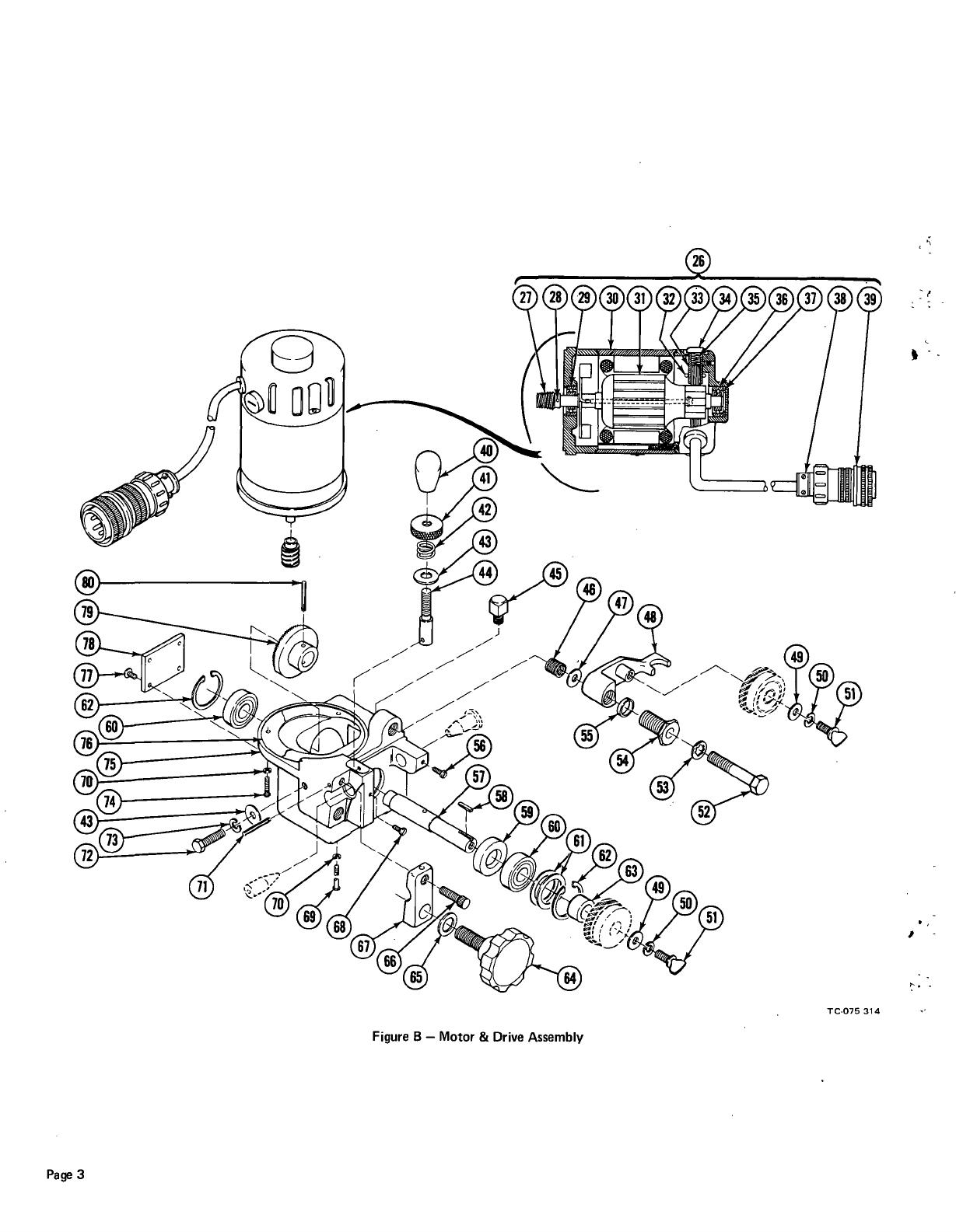
Figure
B
Motor
&
Drive
Assembly
TC-075
314
1

Item
No.
26
27
28
29
30
31
32
33
34
35
36
37
38
39
40
41
42
43
44
45
46
47
48
49
50
51
52
53
54
55
56
57
58
59
60
61
62
63
64
65
66
67
68
69
70
71
72
73
74
75
76
77
78
79
80
075
316
073 702
078
671
073
597
073
762
073
763
073
593
077
214
073
595
*073
591
073
596
075
069
073
296
073
264
073
696
074
911
073
514
602
243
075 057
077
318
073 334
010
910
074
905
604
538
602
211
073
707
605
209
602
221
074
811
074
865
075
532
075
058
056
068
073
309
073
268
073
774
073
240
074
859
073
694
075
099
602
008
079
256
075
553
078
685
078
687
078
672
601
965
602 213
078
686
075 305
073
703
078 462
074
776
073
701
010
224
*Recommended
Spare
Parts
BE
SURE
TO
PROVIDE
STOCK,
MODEL,
AND
SERIAL
NUMBERS
WHEN
ORDERING
REPLACEMENT
PARTS.
1
1
1
1
1
1
2
2
2
2
1
1
1
1
1
1
1
2
1
1
1
1
1
2
2
2
1
1
1
1
1
1
1
1
2
As
Reqd
2
1
1
1
1
1
1
2
3
1
1
1
1
1
1
4
1
1
1
Factory
Part
No.
Description
Quantity
Figure
B
075
314
Motor
&
Drive
Assembly
(See
Fig.
A
Page
2
Item
2)
MOTOR,
drive
(consisting
of)
GEAR,
miter
PIN,
spring
3/32
x
1/2
BEARING
FIELD
ASSEMBLY
ARMATURE
SPRING,
brushholder
HOLDER,
brush
CAP,
brushholder
BRUSH,
contact
BEARING
SHIM
CLAMP,
cable
amphenol
97-3057-12-6
PLUG,
amphenol
6
pin
97-3106A-20-17P
KNOB,
3/8-16
thread
COLLAR,
adjusting
-
tension
SPRING,
compression
WASHER,
flat
-
steel
3/8
FASTENER,
pin
BREATHER,
brass
-
pipe
vent
1/8
NPT
HELl
COIL,
(included
when
ordering
item
75)
WASHER,
flat
-
steel
SAE
3/8
LEVER,
mounting
-
drive
gear
WASHER,
flat
-
steel
SAE
5/16
WASHER,
lock
-
steel
split
5/16
SCREW,
thumb
5/16-18
x
1/2
SCREW,
cap
-
hex
hd
3/8-16
x
2-1/4
WASHER,
lock
-
steel
internal
tooth
3/8
BUSHING,
9/16-18
NF
x
1-5/16
lg
TUBING,
steel
5/8
OD
x
22
ga
x
7/32
SCREW,
pan
hd
1/4-20
x
1/2
SHAFT,
drive
KEY,
steel
1/8
x
1/8
x
1/2
SEAL,
oil
-
drive
shaft
BEARING,
ball
SHIM,
1-3/8
OD
xl
ID
x
.010
thick
RING,
retaining
-
external
TUBING,
steel
7/8
OD
x
9/16
ID
x
31/64
KNOB
WASHER,
steel
27/32
OD
x
17/32
ID
x
3/32
thick
SCREW,
cap
-
steel
socket
hd
1/2-20
x
1
CLAMP,
guide
(included
when
ordering
item
75)
SCREW,
pan
hd
1/4-20
x
5/8
SCREW,
round
hd
12-28
x
3
WASHER,
steel
-
lock
split
No.
12
PIN,
spring
3/16
x
7/8
SCREW,
cap
-
steel
hex
hd
3/8-16
x
1
WASHER,
steel
-
lock
split
3/8
SCREW,
round
hd
12-28
x
3/4
HOUSING,
drive
(includes
items
46
and
67)
GASKET,
motor
SCREW,
truss
hd
-
phillips
10-24
x
1/2
COVER,
bearing
GEAR,
drive
PIN,
spring
3/16
x
1
OM-1500
Page
4

Page
5
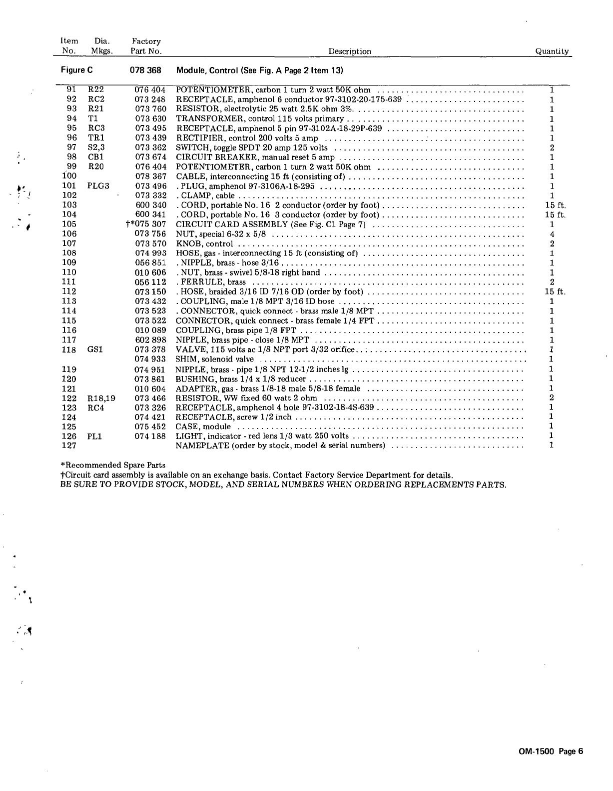
Figure
C
Module,
Control
TC-078
368
Item
Dia.
Factory
No.
Mkgs.
Part
No.
Description
Quantity
Figure
C
078
368
Module,
Control
(See
Fig.
A
Page
2 Item
13)
91
R22
076
404
POTENTIOMETER,
carbon
1
turn
2
watt
50K
ohm
1
92
RC2
073 248
RECEPTACLE,
amphenol
6
conductor
97-3102-20-175-639
1
93
R21
073
760
RESISTOR,
electrolytic
25
watt
2.5K
ohm
3%
1
94
Ti
073
630
TRANSFORMER,
control
115
volts
primary
1
95
RC3
073
495
RECEPTACLE,
amphenol
5
pin
97-3102A-18-29P-639
1
96
TR1
073
439
RECTIFIER,
control
200
volts
5
amp
1
97
S2,3
073
362
SWITCH,
toggle
SPDT
20
amp
125
volts
2
98
CB1
073
674
CIRCUIT
BREAKER,
manual
reset
5
amp
1
99
R20
076
404
POTENTIOMETER,
carbon
1
turn
2
watt
50K
ohm
1
100
078
367
CABLE,
interconnecting
15
ft
(consisting
of)
1
101
PLG3
073
496
.
PLUG,
amphenol
97-3106A-18-295
1
102
073
332
-
CLAMP,
cable
1
103
600 340
-
CORD,
portable
No.
16
2
conductor
(order
by
foot)
15
ft.
104
600
341
.
CORD,
portable
No.
16
3
conductor
(order
by
foot)
15
ft.
105
t*075
307
CIRCUIT
CARD
ASSEMBLY
(See
Fig.
Cl
Page
7)
1
106
073
756
NUT,
special
6-32
x
5/S
4
107
073
570
KNOB,
control
2
108
074
993
HOSE,
gas
-
interconnecting
15
ft
(consisting
of)
1
109
056
851
-
NIPPLE,
brass
-
hose
3/16
1
110
010
606
.
NUT,
brass
-
swivel
5/8-18
right
hand
1
111
056
112
.
FERRULE,
brass
2
112
073
150
-
HOSE,
braided
3/16
ID
7/16
OD
(order
by
foot)
15
ft.
113
073
432
-
COUPLING,
male
1/8
MPT
3/16
ID
hose
1
114
073
523
-
CONNECTOR,
quick
connect
-
brass
male
1/8
MPT
1
115
073
522
CONNECTOR,
quick
connect
-
brass
female
1/4
FPT
1
116
010
089
COUPLING,
brass
pipe
1/8
FPT
1
117
602
898
NIPPLE,
brass
pipe
-
close
1/8
MPT
1
118
GS1
073
378
VALVE,
115
volts
ac
1/8
NPT
port
3/32
orifice
1
074
933
SHIM,
solenoid
valve
1
119
074
951
NIPPLE,
brass
-
pipe
1/8
NPT
12-1/2
inches
lg
1
120
073
861
BUSHING,
brass
1/4
x
1/8
reducer
1
121
010
604
ADAPTER,
gas
-
brass
1/8-18
male
5/8-18
female
1
122
R18,19
073
466
RESISTOR,
WW
fixed
60
watt
2
ohm
2
123
RC4
073
326
RECEPTACLE,
amphenol
4
hole
97-3102-18-4S-639
1
124 074
421
RECEPTACLE,
screw
1/2
inch
1
125
075452
CASE,module
1
126
PL1
074
188
LIGHT,
indicator
-
red
lens
1/3
watt
250
volts
1
127
NAMEPLATE
(order
by
stock,
model
&
serial
numbers)
1
*Recommended
Spare
Parts
tCircuit
card
assembly
is
available
on
an
exchange
basis.
Contact
Factory
Service
Department
for
details.
BE
SURE
TO
PROVIDE
STOCK,
MODEL,
AND
SERIAL
NUMBERS
WHEN
ORDERING
REPLACEMENTS
PARTS.
OM-1500
Page
6

Cl
C2
C3,6
C4
C5
C7
C8
C9
CAL
Q1
Q2
Q3
Q4
Q5
Q6
Q7
R1,8,i0
R3
R4
R5
,1
2
R6,9
R7,i1
Ri
4
R15
Ri
6
REC1,16
REC2,11
REC3
REC4
REC5,6,12,13
REC7,9
REC8
REC1O
REC14
REC15
T2,4
T3
074
201
074
197
073
549
073
460
073
453
073
547
073 714
073
740
See
Note+
073
710
073
789
605
841
077
190
073
712
073
529
073
791
605
918
074
041
605
912
605
911
074
039
074
110
074
026
074
043
074 042
073 539
037
250
073
560
074
246
073
551
073 555
074
453
022 073
037 243
037
095
073
684
073
683
073 946
074
509
Figure
Cl
Circuit
Card
Assembly
1
1
2
1
1
1
1
1
1
1
1
1
1
1
1
3
1
1
2
2
2
1
1
1
2
2
1
1
4
2
1
1
1
1
2
1
1
1
TA.075
307
/
+Resistors
labeled
CAL
on
the
circuit
card
assembly
are
used
to
compensate
for
variations
in
other
circuit
card
component
tolerances.
The
value
of
these
resistors
may
vary
from
circuit
card
to
circuit
card.
If
replacement
is
necessary,
be
sure
a
resistor
of
identical
value
is
used.
If
the
resistor
value
is
indistinguishable,
contact
the
Factory
Service
Department.
BE
SURE
TO
PROVIDE
STOCK,
MODEL,
AND
SERIAL
NUMBERS
WHEN
ORDERING
REPLACEMENT
PARTS.
Dia.
Factory
Mkgs.
Part
No.
Description
Quantity
Figure
Cl
075
307
Circuit
Card
Assembly
(See
Fig.
C
Page
6
Item
105)
CAPACITOR,
mylar
0.1
Ut
4(30
volts
dc
CAPACITOR,
mylar
0.047
uf
100
volts
dc
CAPACITOR,
mylar
0.015
uf
200
volts
dc
CAPACITOR,
electrolytic
2
uf
50
volts
dc
CAPACITOR,
electrolytic
10
uf
150
volts
dc
CAPACITOR,
mylar
0.33
uf
200
volts
dc
CAPACITOR,
tantalum
0.22
uf
35
volts
dc
CAPACITOR,
ceramic
.01
uf
50
volts
TRANSISTOR,
6
amp
200
volts
DIODE,
10
amp
10
volts
THYRISTOR,
6
amp
500
volts
THYRISTOR,
7
amp
200
volts
THYRISTOR,
ac
TRANSISTOR,
unijunction
THYRISTOR,
35
amp
200
volts
RESISTOR,
carbon
0.25
watt
100
ohm
RESISTOR,
carbon
0.25
watt
47K
ohm
RESISTOR,
carbon
0.25
watt
4700
ohm
RESISTOR,
carbon
0.25
watt
10K
ohm
RESISTOR,
carbon
0.25
watt
27K
ohm
RESISTOR,
carbon
1
watt
10K
ohm
RESISTOR,
carbon
0.25
watt
150
ohm
RESISTOR,
carbon
0.25
watt
lOOK
ohm
RESISTOR,
carbon
0.25
watt
82K
ohm
DIODE,
diac
DIODE,
zener
25
volts
1
watt
DIODE,
1
amp
400
volts
DIODE,
zener
75
volts
1
watt
DIODE,
1
amp
600
volts
DIODE,
1
amp
400
volts
RECTIFIER,
integrated
1
amp
600
volts
RECTIFIER,
integrated
18.5
amp
600
volts
DIODE,
zener
18
volts
1
watt
DIODE,
15
amp
200
volts
straight
polarity
TRANSFORMER,
pulse
1
to
1
TRANSFORMER
BLOCK,
terminal
15
amp
16
pole
PRINTED
WIRING
BOARD
Page
7

I
Figure
D
Wire
Guide
and
Drive
Gear
Assembly
TC-076
195
WIRE
GUIDE
INLET
UPPER
DRIVE
GEAR
LOWER
WIRE
GUIDE
GEAR,
DRIVE
OUTLET
OM-1500
Page
8

/