Page is loading ...

© Adam Equipment Company 2019
Adam Equipment
AE 403 Series Indicator
Service Manual
Software revisions V1.00 and above

© Adam Equipment Company 2019
Easy Reference:
Model name of the scale:
Serial number of the unit:
Software revision number
(Displayed when power is first turned on):
Date of Purchase:
Name of the supplier and place:

© Adam Equipment Company 2019
1
1.0 CONTENTS
(P.N. 31066 14213, Revision B, October 2019)
1.0 CONTENTS ................................................................................................................... 1
2.0 INTRODUCTION ........................................................................................................... 2
3.0 SAFETY ......................................................................................................................... 2
4.0 PANEL INTERFACES ................................................................................................... 3
4.1 POWER ...................................................................................................................... 3
4.2 DATA INTERFACES .................................................................................................. 3
4.3 LOAD CELL INTERFACES ........................................................................................ 3
4.4 RELAY INTERFACES ................................................................................................ 3
5.0 INDICATOR MENUS ..................................................................................................... 4
5.1 SUPERVISOR MENUS .............................................................................................. 4
5.1.1 “AdCnT” ................................................................................................................. 5
5.1.2 “dvAL” ................................................................................................................... 5
5.1.3 “APPro” ................................................................................................................. 6
5.1.4 “CAPA” ................................................................................................................... 6
5.1.5 “AVTo-z” ............................................................................................................... 6
5.1.6 “p-zEro” ............................................................................................................... 6
5.1.7 “k-zEro” ............................................................................................................... 7
5.1.8 “FiLtEr” ............................................................................................................... 7
5.1.9 “G1”...................................................................................................................... 7
5.1.10 “G2” .................................................................................................................... 7
5.1.11 “LinEAr” ............................................................................................................. 8
5.1.12 “m-TaRe” ............................................................................................................. 8
5.1.13 “doT” ................................................................................................................... 8
5.1.14 “C-Con” ............................................................................................................... 9
5.1.15 “ReseT” ............................................................................................................... 9
5.2 DEALER MENUS ....................................................................................................... 9
5.2.1 “L-CaL” ............................................................................................................... 10
5.2.2 “AdC” ................................................................................................................... 11
5.2.3 “ GRaviT” ........................................................................................................... 11
5.3 USER MENUS ......................................................................................................... 11
6.0 INDICATOR PARAMETERS ....................................................................................... 12
7.0 RS-232 PARAMETERS RS232 ................................................................................... 15
7.1 Print settings ............................................................................................................ 15
7.2 PC settings ............................................................................................................... 16
7.3 RS-232 INTERFACE ................................................................................................ 16
8.0 CONNECTION OF LOAD CELL .................................................................................. 17
8.1 Connector Assembly ................................................................................................ 17
8.2 Load cell wire solder with PCB ................................................................................. 18
9.0 U-BRACKET ASSEMBLY ............................................................................................ 22
10.0 CHANGING LOAD CELL AND RS232 CABLE .......................................................... 22
11.0 CHANGING BATTERY or BATTERY CABLE ............................................................ 25
12.0 CHANGING TRANSFORMER ................................................................................... 26
13.0 CHANGING OVERLAY .............................................................................................. 28
14.0 ACCESSORIES & SPARE PARTS ........................................................................... 28

© Adam Equipment Company 2019
2
2.0 INTRODUCTION
This Service Manual will guide you through the normal service and calibration procedures
necessary to maintain the indicator. Please read this Manual thoroughly before performing
any service. This manual should be used in conjunction with the User operation manual.
3.0 SAFETY
HIGH VOLTAGE
The indicator has high voltage inside. This high voltage can be lethal.
When using the indicator, indicator power plug must connect to a reliable earthed external
power.
When service the indicator, power must be disconnected, it is essential to separate display
plug from external power.

© Adam Equipment Company 2019
3
4.0 PANEL INTERFACES
The indicator has connectors for the power, data interface, load cell and Relay (option).
4.1 POWER
Make certain your indicator is compatible with the mains power supply in your area. If the
voltage is not the same the indicator can be damaged.
4.2 DATA INTERFACES
The indicator has data interfaces for a variety of applications.
The RS232 interface is a general purpose serial interface for communications with the
indicator, using a connector.
See the User manual section 9.0 for more details.
4.3 LOAD CELL INTERFACES
The indicator has load cell interfaces option, so user can connect it to a weighing platform
for using.
Due to approval or special requirement for application, some indicator models need the
user to connect load cell wire to the PCB board.
See section 11 for more installation details.
4.4 RELAY INTERFACES
The indicator has relay interfaces option. If you need this option, please contact Adam
Equipment or your dealer.
See the User manual section 10.0 for more details.

© Adam Equipment Company 2019
4
5.0 INDICATOR MENUS
The AE 403 has a number of submenus for setting the operation of the indicator and the
communications. In addition to the Supervisors menu for setting the indicator to the needs
of the user, there is a Dealer menu that allows a service person to calibrate the indicator,
observe the ADC counts from the load cell.
Major
function
CHK SET DISP
0
Minor
function
ST PRINT FUNC MODE
Esc
auxiliary
function
CE
All the operations can be performed by the keypad. See user manual section 4.0 for
specific keypad function.
5.1 SUPERVISOR MENUS
•
Press and hold the
[ ]
key about 2 seconds to turn on the indicator, and wait for the
scale to do self-test.
•
Before self-test completes, press the
[
]
key when “
p
” is displayed, enter the
supervisor password information.
• To enter the password, use the directional buttons
[]
to scroll through numbers 1-9. Use
the
[]
directional key to move to the next digit
.
•
Entering the correct password [1946] will bring you to the supervisor menu. The displays
will show the first parameters, called
“AdCnT”.

© Adam Equipment Company 2019
5
•
Press the [
] key to enter a parameter, the display will guide you through the parameter
selected and the options available.
•
To exit a parameter, press the [Esc].
• Press [] or [] key to select other parameters.
• Press the [Esc] key again to return to weighing.
The display will show the available parameters:
5.1.1 “
AdCnT
”
Press the [
] key to enter this parameter. This parameter allows you to view the A/D
counts from the internal A/D converter.
This can be an aid to service.
The weight ADC counts are normally stable within a few counts if the load cell is
functioning correctly, the environment is stable and the temperature is stable. The range of
the ADC counts will depend upon the load cell used and if the bracket is in place or not.
5.1.2
“
dvAL
”
This parameter is dual range.
1
“AdCnT”
Display the A/D counts
2
“dvAL”
whether dual division or dual capacity is necessary
3
“APPro”
Approval type
4
“CAPA”
Capacity
5
“AVTo-z”
Zero tracking range
6
“P-zEro”
Zero rang when power on
7
“k-zEro”
Key zero range
8
“FiLtEr”
Filter mode and range
9
“G1”
Gravitational acceleration at place of manufacture
10
“G2”
Gravitational acceleration at place of use
11
“LinEAr”
Linearity calibration
12
“m-TaRe”
Tare display mode
13
“doT”
Setup dot or comma as decimal
14
“C-Con”
Calibration control
15
“ReseT”
Reset all parameters

© Adam Equipment Company 2019
6
Press the [
] key to enter this parameter, display will show
“nonE”.
Use
[]
or
[]
key to
change parameter, there are
“nonE”, “d-ran G ”, “d-diw”
options available to select,
press [
] to accept the selected parameter
.
“d-ran G ” is dual range, “d-diw” is dual
division.
5.1.3 “
APPro
”
This parameter is for approvals
Press the [
] key to enter this parameter, display will show
“nonE”.
Use
[]
or
[]
key to
change parameter, there are “nonE” , “oimL”, “sa”, “avs”, “ntEp” options
available to select, press [
] to accept the selected parameter.
5.1.4 “
CAPA
”
This parameter sets unit, decimal point, capacity & division
Press the [
] key to enter this parameter, display will show
“dEC”. Use
[]
or
[]
key to
change parameter, there are0,0.0,0.00,0.000,0.0000 parameters available to select,
press [
] to accept the selected parameter.
When the display shows “KG”, use
[]
or
[]
key to change the parameter. There are two
options “KG” and “Lb”
,
press [
] to accept the selected parameter
.
The display will show “CAPA H”
,
then jump to number “0”. Press [CE] key can clear all the
original readings. Use [] or [] key to change the parameter and press [] key to move
to the next digit. Press [
] key to accept the selected parameter.
The display will show
“inC H”,
then jump to reading
“0.001”.
Use
[]
or
[]
key to change
the parameter and select suitable precision. There are 1,2,5, 10 parameters available
to select. After selecting the suitable precision, press [
] to accept the selected parameter
.
5.1.5 “
AVTo-z
”
This parameter sets the Auto zero range
Press the [
] key to enter this parameter, display will show “2.0”. Use
[]
or
[]
key to
change parameter, there are 0.5,1.0,1.5,2.0,2.5,3.0 parameters available to select,
press [
] to accept the selected parameter.
5.1.6 “
p-zEro
”
This parameter sets the power on zero range

© Adam Equipment Company 2019
7
Press the
[
]
key to enter this parameter, the display will show
“10”.
Use
[]
or
[]
key to
change parameter, there are
off,
1,2,5,10,20,50,100 parameters available to
select, press [
] to accept the selected parameter.
5.1.7 “k
-zEro
”
This parameter is for approved units only to set the allowable range for zero when key
pressed
Press the [
] key to enter this parameter, the display will show “4”
.
Use
[]
or
[]
key to
change parameter, there are1, 2,4,5,10,20 parameters available to select, press [
] to
accept the selected parameter.
5.1.8 “
FiLtEr
”
This parameter sets the filter
Press the [
] key to enter this parameter, the display will show “A CLr”
.
Use
[]
or
[]
key to change parameter, there are “SLowEr”, “SLowEs”, “FAStEs”, “FAStEr”
parameters available to select, press [
] to accept the selected parameter and move to
the next menu.
Use
[]
or
[]
key to change the parameter and press [
] to accept the selected
parameter
.
5.1.9 “G
1
”
This parameter sets the gravity zone
Press the [
] key to enter this parameter, the display will show a value. Use []
or
[]
key to
enter the actual acceleration of gravity for calibration location, then press [
] to accept
.
5.1.10 “G
2
”
This parameter allows you to select a pre-set gravity zone
Press the [
] key to enter this parameter, display will show “VSER”
.
Use
[]
or
[]
key to
change parameter, there are “VSER”, “V k ”, “fr1”, “fr2”, “fr3” ,“fr4”, “nL”,
“Ge”,“itA”, “SA”, “VSA”, “aVs” parameters available to select, press [
] to accept the
selected parameter.
If the location is not included in the area above, please select
“VSER”
,
the display will show
a value, press [CE] key can clear original readings. Use
[]
or
[]
key to change the
parameter, use [] key to move to the next digit, enter the actual acceleration of gravity
for operation location and press [
] to accept.

© Adam Equipment Company 2019
8
5.1.11 “
LinEAr
”
This parameter allows you to do linearity calibration
• Press [
] key to access linearity calibration parameter, the display will show “
~
NoLoAD”
.
Make sure the weighing platform is empty and press [
] key to accept
.
•
The display shows “KG”, use
[]
or
[]
key to change the parameter. There are “KG”
and “Lb”
parameters, press [
] to accept the selected parameter.
•
The display shows “LoAD 1”
,
then jumps to “1.000”
,
the last digit is flashing. Press [CE]
key can clear original readings. Use
[]
or
[]
key to change the parameter, use [] key
to move to the next digit. Generally load 1 is set to1/2 of the capacity. Select integer for
actual weight and press [
] to accept.
•
When the display shows
“
~
LoAD”
,
put specified weight on the weighing platform. When
stable symbol appears again, press [
] to accept.
•
The display shows“
~
LoAD 2”
, then jumps to
“3.000”
,
the last digit is flashing. Press [CE]
key can clear original readings. Use
[]
or
[]
key to change the parameter, use [] key
to move to the next digit. Generally load 2 is set to full capacity. Select integer for actual
weight and press [
] to accept.
•
When the display shows “
~
LoAD”
,
put specified weight on the weighing platform. When
stable symbol appears again, press [
] to accept.
• Software will restart and display weighing status, now linearity calibration completes
.
5.1.12 “
m-TaRe
”
This parameter sets automatic tare
Press the [
] key to enter this parameter, the display will show “A CLr”. Use [] or []
key to change parameter, there are
“A CLr”
and
“disp”
parameters available to select,
press [
] to accept the selected parameter
.
“A CLr”
automatically clears the tare when
the reading goes to zero
,
“disp”
shows the tare value, and only allows, manual clearing of
the tare.
5.1.13 “
doT
”
Sets whether the decimal point is displayed as a dot or a comma.

© Adam Equipment Company 2019
9
Press the [
] key to enter this parameter, the display will show “doT”
.
Use
[]
or
[]
key
to change parameter, there are
“doT”
and
“Comm”
parameters available to select, press
[
] to accept the selected parameter.
5.1.14 “
C-Con
”
For approved units only, this parameter sets the calibration control
Press the [
] key to enter this parameter, the display will show
“Covnt”
.
Use
[]
or
[]
key to change parameter, there are “Covnt”
and “Jvmp”
parameters available to select,
press [
] to accept the selected parameter
.
“Covnt”
increments each time the indicator is
calibrated, which can then be used for traceability
,
“Jvmp”
calibration can only occur when
a jumper is fitted.
Note: if you select “Jvmp”
and accept it, you can only access the menu through the jumper
on the PCB.
5.1.15 “
ReseT
”
This parameter is factory reset.
Press the [
] key to enter this parameter, the display will show “no”
.
Use
[]
or
[]
key to
change parameter, there are “no”
and
“Yes”
parameters available to select, press [
] to
accept the selected parameter.
Note: if you select “Yes”
and accept it, all parameters will reset to factory and the indicator
will restart.
Details of these menus are given in the User manual section 12
.
5.2 DEALER MENUS
The dealer has access to a menu to allow calibration of weight without the normal
limitations put on the calibration during the user methods of setting them. In addition it is
possible to view the values delivered from the analog to digital converter for both the
chamber temperature and the weight.
This section describes the parameters available to the dealers for setting up the indicator.
Access to these parameters is controlled by password.

© Adam Equipment Company 2019
10
•
Press and hold the[ ] key about 2 seconds to turn on the indicator, and wait for the
scale to configure.
•
Before configuration is completed, press the [
] key, when “
p
”
is displayed, enter
the dealer password information screen.
•
To enter the password, use the directional buttons
[]
to scroll through numbers 1-9.
Use the [] directional key to move to the next digit.
•
Entering the correct password [1966] will bring you to the supervisor menu.
The displays
will show the first parameters, called
“L-CAL”
.
•
Press the [
] key to enter a parameter, the display will guide you through the parameter
selected and the options available
.
•
To exit a parameter, press the [Esc]
Use the
[]
or [] directional key to select other parameters.
• Press the [Esc] key again to return to weighing.
The display will show the parameters available:
5.2.1 “
L-CaL
”
•
Press [
] key to access linearity calibration parameter, the display will show “
~
NoLoAD”
.
Make sure the weighing platform is empty and press [
] key to accept
.
•
The display shows “KG”, use [
] or [] key to change the parameter. There are “KG”
and “Lb”
parameters, press [
] to accept the selected parameter
.
•
The display shows “LoAD 1”
,
then move to “1.000”
,
the last digit is flashing. Press [CE]
key can clear original readings. Use
[]
or
[]
key to change the parameter, use [] key
to move to the next digit. Generally load 1 is set to1/2 of the capacity. Select integer for
actual weight and press [
] to accept.
1
“L-CAL”
Linearity calibration
2
“adC”
Display the A/D counts
3
“
G
RaviT”
Gravitational acceleration at place of use

© Adam Equipment Company 2019
11
•
When the display shows “
~
LoAD”
,
put specified weight on the weighing platform. When
stable symbol appears again, press [
] to accept
.
•
The display shows“
~
LoAD 2”
,
then jumps to“3.000”
,
the last digit is flashing. Press [CE]
key can clear original readings. Use
[]
or
[]
key to change the parameter, use [] key
to move to the next digit. Generally load 2 is set to full capacity. Select integer for actual
weight and press [
] to accept.
•
When the display shows “
~
LoAD”
,
put specified weight on the weighing platform. When
stable symbol appears again, press [
] to accept
•
Software will restart and display weighing status, now linearity calibration completes
.
5.2.2
“
AdC
”
Press the [
] key to enter this parameter. This parameter allows you to view the A/D
counts from the internal A/D converter.
This can be an aid to service.
The weight ADC counts are normally stable within a few counts if the load cell is
functioning correctly, the environment is stable and the temperature is stable. The range of
the ADC counts will depend upon the load cell used and if the bracket is in place or not
.
5.2.3
“
G
RaviT
”
This parameter allows you to select a pre-set gravity zone
Press the [
] key to enter this parameter, the display will show “VSER”
.
Use
[]
or
[]
key
to change parameter, there are “VSER”, “V k ”, “fr1”, “fr2”, “fr3” ,“fr4”, “nL”,
“Ge”,“itA”, “SA”, “VSA”, “aVs” parameters available to select, press [
] to accept the
selected parameter.
If the location is not included in the area above, please select “VSER”,
the display will show
a value, press [CE] key can clear original readings. Use
[]
or
[]
key to change the
parameter, use [] key to move to the next number, enter the actual acceleration of
gravity for operation location and press [
] to accept.
5.3 USER MENUS
The user has access to a menu to allow calibration of weight without the normal limitations
put on the calibration during the user methods of setting them
.

© Adam Equipment Company 2019
12
This section describes the parameters available to the dealer for setting up the indicator. Access to
these parameters is controlled by password.
•Press and hold the[ ] key about 2 seconds to turn on the indicator, and wait for the
scale to configure.
• Before configuration is completed, press the [
] key when
“
p
”
is displayed, enter the
user password information screen.
•
To enter the password, use the directional buttons
[]
to scroll through numbers 1-9.
Use the [] directional key to move to the next digit.
•
Entering the correct password [1000] will bring you to the user menu.
The displays will
show the first parameters, called
“
~
NoLoAD”.
•
Make sure the weighing platform is empty and press [
] key to accept.
•
The display shows “LoAD 1”
,
then jumps to “1.000”
,
the last digit is flashing. Press [CE]
key can clear original readings. Use
[]
or
[]
key to change the parameter, use [] key
to move to the next digit. Generally load 1 is set to full capacity. Select integer for actual
weight and press [
] to accept.
•
When the display shows “
~
LoAD”
,
put specified weight on the weighing platform. When
stable symbol appears again, press [
] to accept.
•
Software will restart and display weighing status, now user calibration completes.
6.0 INDICATOR PARAMETERS
•
Pressing the [SET/FUNC] key and holding for 2 seconds during normal operation allows
the user to access the parameters.
• Scroll through the list of functions using the
[] and []
directional keys. Press [
] to
enter a parameter.
• Press [Esc] to exit the scale parameter section and return to normal weighing.
This group of parameters is used to control the operation of the scale.

© Adam Equipment Company 2019
13
Parameter Description Options Default
setting
time
Set Time.
Enter the time manually.
00:00:00
date
Set date format and settings.
Format for date can be
changed when the display
shows mmddyy, ddmmyy or
yymmdd by pressing the
[Pcs/]
key, then enter the
date.
Enter the date format
and then the numeric
value manually.
mm:dd:yy
bL
Backlight set to always on,
always off or automatic on.
Set color and brightness
oFF, on, AUTO
then: GREEN, RED, AMBER,
BLUE, WHITE
then: mid, high, low
AUTO
Power
Disable or set time
increment to turn off scale
0, 1, 2, 5, 10, 15, Off
2
Key bp
Key beeper settings
On, Off On
Chk bp
Check weighing beeper
settings
In, Out, Off In
Unit
Enable or disable weighing
units, will not allow to
disable all units, at least one
has to be enabled. Parts
counting can be
enabled/disabled
Kg
Grams
lb
oz
lb:oz
N (Newtons)
PCS
Kg
Auto-Z
Auto zero settings 0.5, 1, 1.5, 2, 2.5, 3
0.5
Filter
Filter setting to slow, normal
or fast
Slower, Slowest, Faster,
Fastest
Then: 1-6
Faster
Rs 1
Brings up the 1
st
RS232
menu. Includes PC,
command and print settings
PC, Cmd, Print
Rs 2
Brings up RS232 menu 2 PC, Cmd
S-id
Set Scale ID
To be entered manually
000000
U-id
Set User ID To be entered manually 000000
rechar
Indicates time to recharge
-
-

© Adam Equipment Company 2019
14
Parameter
Description
Options Default
setting
time
time setting
Manual input
00:00:00
date
Use [] and [] to select
proper date format from
mmddyy, ddmmyy,
yymmdd and enter the date
Select date format and
input correct date
mm:dd:yy
bL
Backlight set to always on,
always off or automatic on.
Set color and brightness
oFF, on, AUTO
then: GREEN, RED, AMBER,
BLUE, WHITE
then: mid, high, low
AUTO
Power
Set auto power-off time
0, 1, 2, 5, 10, 15, Off 2
Key bp
Set keypad tone
On, Off On
Chk bp
S
et weight checking sound
In, Out, Off In
Unit
Set weight unit
Kg, Grams, lb, oz, lb:oz,
N (Newtons), PCS
Kg
Auto-Z
Auto zero setting 0.5, 1, 1.5, 2, 2.5, 3
0.5
Filter
F
ilter setting
Slower
Slowest
Faster
Fastest
1-6 grade available to select
Faster
Rs 1
Set 1# RS232 interface,
including PC, command,
print setting
PC, Cmd, Print
Rs 2
S
et 2# RS
232
interface
PC, Cmd
S-id
Set number for the scale Manual input
-
U-id
S
et operator number
M
anual input
-
rechar
Display charging current
-
-
1.

© Adam Equipment Company 2019
15
7.0 RS-232 PARAMETERS RS232
This group of parameters can be set by the user for setting the RS-232 active or not, baud
rate, printing mode, accumulation mode, RS-232 language, and user or scale ID numbers.
• Pressing the [Func/Set] key and holding for 2 seconds during normal operation
allows the user to access the parameters.
• Scroll through the list of functions using the
[]
and [] directional keys. Press [
]
to enter the ‘rs 1’ or ‘rs 2’ parameters when appearing on the display.
• ‘Rs 1’ will provide access to ‘Print’ and ‘PC’ settings. ‘Rs 2’ includes ‘PC’ and
‘Print’. Press [
] to confirm.
• When entering a mode, the user will be required to go through each step of the
process by entering the desired values or selecting from the options listed in the
table below and pressing the[
] key to confirm.
• Press [Esc] to exit the scale parameter section and return to normal weighing.
7.1 Print settings
Parameter Description Options Default Values or
setting
[baud rate]
Baud Rate
1200
2400
4800
9600
19200
38400
57600
115200
9600
[Language]
Select Language
EnGLis (English)
FrEnCH (French)
SPAn (Spanish)
GErmAn (German)
Itail
(Italian)
Portug
(Portuguese)
EnGLis
[Accumulation]
Enable or disable the
Accumulation
on
oFF
off
[Printing mode]
Printing Mode
-
Manual
or Automatic
mAn,
AUto P
mAn
[Printer/device]
Select the printer or
device to print to
ATP
LP50
ATP
[Number of
copies]
Select the number of
copies
Copy 1
Copy 2
Copy 3
Copy 4
Copy 5
Copy 6
Copy 7
Copy 8
Copy 1

© Adam Equipment Company 2019
16
[Print layout]
Select complex or
simple print layout
Comp
Simp
Comp
[Line break]
Select the number of
line breaks between
weight values on label.
1 Lfcr
2 Lfcr
3 Lfcr
4 Lfcr
5 Lfcr
6 Lfcr
7 Lfcr
8 Lfcr
9 Lfcr
none
none
Indicator will perform the following, depending on the Accumulation and Print Settings:
ACCUMULATION
SETTINGS
PRINT SETTINGS
AC on
AC Off
AUto
Accumulate and print
automatically
Print automatically,
Do not accumulate
mAn
Accumulate and Print only
when [CHK/PRINT/] key
pressed. If [CHK/PRINT/] is
pressed a second time only
print the weight.
Print when
[
CHK
/
PRINT
/
]
key is
pressed,
Do not accumulate.
7.2 PC settings
Parameter
Description
Options
Default
Values or
setting
[baud rate]
Baud Rate
1200, 2400, 4800, 9600,
19200, 38400, 57600, 115200
9600
[Model]
Select the scale/model being
used.
Adam
CBK
NBL
Adam
[Interval]
Select the interval per
second for sending data to a
PC.
0(continuous) -6.0 Int 6.0
7.3 RS-232 INTERFACE
The AE 403 indicator is supplied with bi-directional RS-232 interface as standard. The
scale when connected to a printer or computer outputs the weight with the selected
weighing unit through the RS-232 interface.

© Adam Equipment Company 2019
17
Specifications:
RS-232 serial interface is a plug as figure 2 shows:
8.0 CONNECTION OF LOAD CELL
8.1 CONNECTOR ASSEMBLY
If there is a metal dust cap at the indicator load cell interface, you need to screw it out
anticlockwise, then you can see a plug like the picture below shows.
RS-232 output of weighing data
ASCII code
9600 Baud (user selectable)
8 data bits
No Parity
1: Pin GND, Signal Ground
2: Pin RXD, Received Data
3: Pin TXD, Transmitted Data
6: Pin +IN +Signal
7: Pin –IN -Signal
3: Pin AGND Shield
1: Pin +E, +Excitation
2: Pin +S +Sense
4: Pin –E -Excitation
5: Pin -S -Sense

© Adam Equipment Company 2019
18
Take out the connector from the box and solder it to load cell wire with the orders above
correctly, then connect the connector to the indicator.
Note:
For 4 wire load cell, connect the load cell +Excitation and +Sense together at the
connector and -Excitation and -Sense together at the connector.
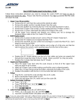
8.2 LOAD CELL WIRE AND PCB SOLDERING
If there isn’t a metal cover at load cell interface, but a rubber cap, then connect the load
cell wire to the indicator correctly as the following steps. Before connecting the wire,
please make sure external power has been cut off.
8.2.1 Screw out 12 screws at the back of the indicator with correct tool and keep the
screws properly.
Rubber
end
screwx12
/