Page is loading ...

Installation
Instructions
34" Integrated Panel With
Diagnostic System
Unpacking Notes
• Concealed Damage. If there should be damage of
such nature that it could not be detected until the
goods were unpacked, have the Transportation
Company's Agent come AT ONCE and inspect them.
Require them to give you a "concealed" bad order
report stating the condition of the goods when exam-
ined. It is their duty to do this and you should INSIST
upon it.
• If the Above Instructions are Complied With, we
shall cheerfully render all possible assistance in
establishing claims against the Transportation Com-
pany for loss and damage in transit.
• We Do Not Accept Goods Returned For Credit,
Exchange, Repairs, or for any other reason, unless
you have first communicated with us and secured our
written permission.
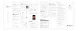
Installation
NOTE
The Integrated Panel is mounted to the wall using steel
mounting bracket (provided with the unit). Wall anchors
and drywall screws are also provided to secure the
mounting bracket to the wall. Figures 1 and 2 are
suggested mounting configurations and locations only.
1. Using the customer or room layout drawing, determine
where the Integrated Panel will be located. See Figure
1 for the suggested room layout.
2. Measure and mark the mounting locations of the
mounting bracket on the wall. See Figure 2.
3. Locate and mark the location of studs in reference to
mounting bracket; an electronic stud finder may be
useful.
NOTE
This note applies to steps 4 thru 6. When securing
mounting brackets to a wall with metal studs, use sheet
metal screws in place of drywall screws and when
securing mounting brackets to a masonry / concrete block
wall, use masonry screws in place of drywall screws and
wall anchors.
4. Place the mounting bracket in position on wall and
mark the locations of all fasteners. Remove the
mounting bracket and drill a 3/8 in. hole where all wall
anchors are to be used; four holes per mounting
bracket if a wall stud is not located and three holes per
mounting bracket if a wall stud is located.
5. Install a wall anchor in each hole. Install a screw in
each wall anchor and tighten far enough to secure the
wall anchor in place. Then, remove all screws from the
wall anchors.
6. Attach mounting brackets to the wall using wall anchor
screws. Level the mounting bracket before securing to
the wall.
7. Test the mounting bracket for strength.
8. Mount the instruments to the Integrated Panel as
follows using Figure 3, 4, 5, 6 or 7 to properly position
the instruments:
Position the Aneroid Blood Pressure Unit on the single
screw provided and then secure top of unit in place
using two additional screws provided. Install (hang)
the remaining instrument assemblies on the pre-
installed mounting screws.
Position the Sure Temp Plus on the two screws
provided and then secure the unit in place using two
additional screws provided.
9. Lift the Integrated Panel onto their mounting brackets.
© Midmark Corporation - 1997
®
Sheet 1 of 2
FIGURE 1. SUGGESTED ROOM LAYOUT
10'-0"
STOOL
8'-0"
DRESSING
NOOK
CASEWORK
MA318401
SIDE
CHAIR
INTEGRATED
PANEL
EXAM
TABLE
Attention!
For OSHPD Regulated Installations, please go to
www.midmark.com to download the appropriate
OSHPD Pre-Approval and Installation documents.
Next
Style A

MA738100i
Spot Vital Signs LXi
MA417700
Aneroid Blood
Pressure Unit
Wall Transformer For
Otoscope/Ophthalmoscope
KleenSpec
Dispenser
1
0
2
0
4
0
6
0
8
0
1
0
0
1
2
0
1
4
0
1
6
0
1
8
0
2
0
0
2
4
0
2
6
0
2
8
0
3
0
0
Tycos
SureTemp 4
Unit
MA417800
Aneroid Blood
Pressure Unit
Wall Transformer For
Otoscope/Ophthalmoscope
KleenSpec
Dispenser
1
0
2
0
4
0
6
0
8
0
1
0
0
1
2
0
1
4
0
1
6
0
1
8
0
2
0
0
2
4
0
2
6
0
2
8
0
3
0
0
Tycos
FIGURE 2. MOUNTING BRACKET POSITIONING
ON WALL
FIGURE 3. INSTRUMENT LOCATION FOR AN
INTEGRATED PANEL - WITHOUT THERMOMETER
Sheet 2 of 2
For questions or information regarding the medical
instruments on the Integrated Panel, contact Welch
Allyn, Inc. at 4341 State Street Road, Skaneateles
Falls, NY 13153. [Tel: 315-685-4560]
© Midmark Corporation - 1997
003-0898-00 Rev. G (1/10)
67 7/8"
INTEGRATED
PANEL
FLOOR
12
34
7 3/4"
MA318304
FIGURE 6. INSTRUMENT LOCATION FOR AN
INTEGRATED PANEL - WITH SPOT VITAL SIGNS
®
FIGURE 7. INSTRUMENT LOCATION FOR AN
INTEGRATED PANEL - WITH SPOT LXI
®
FIGURE 4. INSTRUMENT LOCATION FOR AN
INTEGRATED PANEL - WITH SURE TEMP 4
THERMOMETER
®
FIGURE 5. INSTRUMENT LOCATION FOR AN
INTEGRATED PANEL - WITH SURE TEMP PLUS
THERMOMETER
®
1
0
2
0
4
0
6
0
8
0
1
0
0
1
2
0
1
4
0
1
6
0
1
8
0
2
0
0
2
4
0
2
6
0
2
8
0
3
0
0
Tycos
MA510602
Spot Vital Signs
MA738000i
Back
/