Page is loading ...

4211-1641 05/30/19 Technical Support: 1-800-363-0251 [email protected] 1 of 29
COMMERCIAL STEAM GENERATOR
WITH COOLFLUSH™ AUTO DRAIN OPTION
AND INTEGRAL LOW WATER CUT-OFF
BOILERS FOR LARGE STEAM ROOMS
INSTALLATION INSTRUCTIONS
230/240V~N, 50/60Hz – MODELS AI-12, AI-18 & AI-24
400/415V~3, 50/60-Hz – MODELS AI-12, AI-18, AI-24, and
AI-30, AI-36, AI-42 & AI-48

4211-1641 05/30/19 Technical Support: 1-800-363-0251 [email protected] 2 of 29
INDEX
SECTION PAGE
WARNINGS 3-6
GENERAL INFORMATION 7
WATER QUALITY REQUIREMENTS 7
BOILER RATINGS 8
INSPECTION INFORMATION 9
DIMENSIONS 10
INSTALLATION 11
GENERATOR 11
PLUMBING 11
WATER LINE 11
STEAM LINE 12
SAFETY VALVE 13
DRAIN 13
ELECTRICAL SERVICE 12
ROOM CONTROLS 14
TEMPERATURE SENSOR 14
THERMOSTAT 15
ROOM SWITCH (I60 or other) 15
and Bath Time Settings
REFRESH SWITCH 16
WIRING DIAGRAM – CONTROL CIRCUITS 17
WIRING DIAGRAM – POWER AND CONTACTOR 18
STARTING THE GENERATOR 19
OPERATING INSTRUCTIONS 20
BOILER START 20
STEAM ROOM OPERATION 20
THE THERMOSTAT 21
THE I60 SWITCH 21
THE REFRESH™ SWITCH 21
LIGHTS AND SWITCHES 21
ROUTINE MAINTENANCE 22
WATER LEVEL CONTROL 22
LOW WATER CUT-OFF (LWCO) 22
BLOWDOWN - CoolFlush™ AUTO DRAIN OPTION 23
BLOWDOWN - MANUAL DRAIN 24
APPENDIX 1: RUN CLOCK AND AUTOBLOWDOWN TIMERS 25
APPENDIX 2: RUN AND AUTOBLOWDOWN DIGITAL CLOCKS 27
APPENDIX 3: PRESSURE CONTROL ASSEMBLY 29

4211-1641 05/30/19 Technical Support: 1-800-363-0251 [email protected] 3 of 29
WARNING
SAVE THIS MANUAL
A MANUFACTURER’S REPORT: CONTROLS AND SAFETY DEVICES is supplied with each generator.
You may be required to present this form to a state, provincial or other inspection agency.
Secure this document in a safe location.
Thank you for purchasing your new AMEREC steam generator.
If we can be of any assistance do not hesitate to call our Technical Support at 1-800-363-0251.
FOR THE SAFETY OF YOU AND YOUR FAMILY OR CUSTOMERS, PLEASE READ THE FOLLOWING
WARNINGS AND ALL INSTRUCTIONS BEFORE USING YOUR STEAMBATH.
POST "STEAMBATH INSTRUCTIONS" LABEL OUTSIDE STEAMBATH FOR SAFETY WARNINGS.
FOR THE SAFETY OF YOU AND YOUR FAMILY OR CUSTOMERS, PLEASE READ THE
FOLLOWING WARNINGS AND ALL INSTRUCTIONS BEFORE USING YOUR STEAMBATH.
POST "STEAMBATH INSTRUCTIONS" LABEL OUTSIDE STEAMBATH FOR SAFETY WARNINGS.
Electric Shock Hazard - High voltage exists within this equipment. Disconnect all electrical power
before servicing the generator. All installation and service to this equipment should be performed by
qualified licensed personnel in accordance with local and national codes. There are no user
serviceable parts in this equipment.
Electrical grounding is required on all AMEREC steambath generators. The generator is designed for hookup
with copper wire only, 75°C or better.
Wire the controls exactly as described. Do not connect any additional wiring or power supplies to the controls or
their terminals in the generator.
Service only by authorized personnel!
All plumbing must be installed by a licensed plumber in accordance with all applicable local and national codes.
Install indoors only. Protect from freezing. Generator must be level side to side and end to end.
The pressure relief valve and generator drain must be installed in such a fashion that the risk of scalding is
reduced to a minimum. Draining these outlets into the steam room may present a scald hazard and may damage
materials used to construct the room.
Danger To reduce the risk of explosions, do not interconnect steam lines!!
Caution The steam outlet carries hot vapor! A separate steam line is required for each steam outlet.
Do not connect a valve or shut-off in the steam line! Avoid traps and valleys in the steam line where
water could collect and cause a steam blockage. The hot steam line must be insulated against user contact.
Do not install the steam head near a bench or where steam may spray or where condensation will drip on the
user as this will present a scald hazard.
Be certain that steambath enclosures are properly sealed to avoid water damage from escaping steam. It is
recommended that 100% silicone caulk be used to seal all pipes and fittings. Steam must be prevented from
escaping into the wall cavity. Centering the steam pipe is critical in rooms made of plastic, acrylic, resin,
fiberglass or similar materials. Allowing the steam pipe to touch materials not rated 115°C or higher will result in
damage to these materials.

4211-1641 05/30/19 Technical Support: 1-800-363-0251 [email protected] 4 of 29
POST "WARNING LABEL OUTSIDE STEAMBATH FOR SAFETY WARNINGS. REQUIRED POSTING ON
DOOR OF STEAM ROOM OR ADJACENT TO DOOR FOR ALL COMMERCIAL INSTALLATIONS.

4211-1641 05/30/19 Technical Support: 1-800-363-0251 [email protected] 5 of 29
IMPORTANT USER SAFETY INSTRUCTIONS
1. READ AND FOLLOW ALL INSTRUCTIONS.—SAVE THESE INSTRUCTIONS!
2. The steam bath is not intended for use by anyone (including children) with reduced physical, sensory or
mental capabilities or who lack experience or knowledge, unless they have supervision or training on the use
of the steam bath by a person responsible for their safety.
3. WARNING - To reduce the risk of injury, do not permit children to use this product unless they are closely
supervised at all times. Ensure they do not play in the steam bath.
4. WARNING - To reduce the risk of injury:
a. The wet surfaces of steam enclosures may be slippery. Use care when entering or leaving.
b. The steam head is hot. Do not touch the steam head and avoid the steam near the steam head.
c. Prolonged use of the steam system can raise excessively the internal human body temperature and
impair the body’s ability to regulate its internal temperature (hyperthermia). Limit your use of steam to 10
to 15 minutes until you are certain of your body’s reaction.
d. Excessive temperatures have a high potential for causing fetal damage during the early months of
pregnancy. Pregnant or possibly pregnant women should consult a physician regarding correct
exposure.
e. Obese persons and persons with a history of heart disease, low or high blood pressure, circulatory
system problems, or diabetes should consult a physician before using a steam bath.
f. Persons using medication should consult a physician before using a steam bath since some medication
may induce drowsiness while other medications may affect heart rate, blood pressure and circulation.
5. WARNING - Hyperthermia occurs when the internal temperature of the body reaches a level several degrees
above the normal body temperature of 37°C. The symptoms of hyperthermia include an increase in the
internal temperature of the body, dizziness, lethargy, drowsiness and fainting. The effects of hyperthermia
include:
a. Failure to perceive heat:
b. Failure to recognize the need to exit the steam bath:
c. Unawareness of impending risk:
d. Fetal damage in pregnant women:
e. Physical inability to exit the steam bath: and
f. Unconsciousness.
6. WARNING - The use of alcohol, drugs or medication can greatly increase the risk of hyperthermia

4211-1641 05/30/19 Technical Support: 1-800-363-0251 [email protected] 6 of 29
GENERAL INFORMATION: The AI Commercial Steam Generator is a low
pressure heating boiler, UL/CUL Listed, built to NEC requirements and with an ASME “H”
stamped certified and National Board registered pressure vessel.
The generator has all steel construction with powder coated finish on visible surfaces and stainless steel
mounting feet to minimize the risk of corrosion. The mounting feet hold the generator one inch above the floor to
allow cleaning the floor below it and to further prevent corrosion. This also allows the generator to sit directly on a
combustible surface without additional protection. The feet extend beyond the sides of the generator chassis and
have clearance holes to allow securing the generator in place using ¼” bolts.
AI Commercial Steam Generators are factory assembled and tested and ready to install. All generators are
plumbed for a ½” potable water feed inlet, a ¾” drain discharge and a ¾” pressure relief valve discharge.
Generators are available for connection to 240V~N or 415V~N. All models require the appropriate full power
electrical service plus ground. Neutral and 240V for the control circuit may be tapped from the Mains terminal
block. Use 75° minimum copper wire for all service connections. A ¾”-1”-1½”-2” combination knockout is
provided in the generator’s electrical box for the main service conduit and an additional ½”-¾” knockout is
provided for extra convenience.
The generator’s control circuit is protected by a 250VAC 3A non-time-delay fuse installed in the front panel of the
generator’s electrical box. No other fusing is installed in the steam generator.
Room controls (
ON/OFF, thermostat, temperature sensing and steam Refresh™) are connected during generator
installation using factory supplied wire or cables. Room controls operate on a low voltage Class 2 circuit. An
access hole and ½” trade size knockouts, are provided for room control wiring. The thermostat must be mounted
outside the steam room, the temperature sensor must be mounted inside the steam room, the optional Refresh™
switch mounts inside the steam room, and the optional
I60 Bath On/Off switch must mount outside the steam
room. Temperature sensors require factory supplied cables for connection to the generator, all other controls
require 3 conductors, 18 to 24 AWG copper, 75° 300V minimum (15 M long cables are provided, longer cables
may be available: contact Technical support for assistance).
Standard equipment:
Manual operation (generator mounted RUN switch and manual ball valve drain) and single steam room (one
steam valve, one temperature sensor, one thermostat with integral steam bath
ON/OFF switch and bath-on
indicator light, two steam heads).
Switches allowing manual heat and water control during routine service, lights indicating heat and valve
operating status and self-check fault codes.
A built in automatically resetting Low Water Cut Off and a built in manual reset LWCO.
Optional equipment:
Second steam room (second steam valve, thermostat and temperature sensor) factory installed only!
RUN CLOCK (7-day or 24 hour programmable time clock or 7-day programmable digital clock for generator
ON/OFF scheduling).
CoolFlush™ Auto Drain consisting of a ¾ inch electronically operated ball valve and a time clock. (7-day or
24 hour programmable time clock or 7-day programmable digital clock for generator are available).
I60 Steam bath on/off switch: commercial (mounts to single gang switch box in a dry location only). Bath
time is switch selectable for automatic bath time out of 15, 30 or 60 minutes using a switch on the boiler’s
circuit board.
Steam bath
ON/OFF switch: residential (membrane switch, may be mounted in steam room) operates the
same as the
I60.
Steam Refresh™ (membrane switch for mounting inside steam room, status indicator light).
Water Quality Requirements:
The nature of a steambath generator requires testing of the feedwater to avoid potential high concentrations of
impurities which can cause a deposit or scale to form on the internal surfaces. This deposit or scale can interfere
with the equipment’s proper operation and even cause premature generator failure. Concentration of impurities is
generally controlled by treating the feedwater and/or “blowing down” the generator when it is not heating. The

4211-1641 05/30/19 Technical Support: 1-800-363-0251 [email protected] 7 of 29
“blow down” process involves removing a portion of the tank water with high solid concentration and replacing it
with makeup water.
To reduce corrosion and element damage risks, always flush new feedwater lines thoroughly to eliminate flux
residue and avoid sodium based water softeners. The ASX-200 filter system available from Amerec provides
very good protection in most installations and should be connected to a cold water supply. Feedwater
temperature must be no hotter than 38°C if the ASX-200 is installed! Contact Technical support for more
information.
To insure proper operation, the water supply should be tested prior to operating the equipment. There are
several treatment processes which can be used if you have a problem with hard water. A local reliable water
treatment company can recommend the appropriate treatment if required. The recommended feedwater quality is
listed below.
Feedwater Quality
Hardness, ppm 10 – 30
T-Alkalinity, ppm 150 – 700
Silica, ppm 15 – 25
PH (strength of alkalinity) 10.5 – 11.5
IMPORTANT! Regular maintenance will help your steamer work properly for a long time. Check for leaks, loose
or damaged wires, signs of corrosion and calcium build up in the tank and on the level probe.
This is particularly important in areas with high calcium levels and other water quality problems. Calcium buildup
can cause poor steamer performance and damage the heating elements!
AMEREC AI BOILER RATINGS
CATALOG#
UL MODEL#
WATTS
VOLTS
PHASE
AMPS
MAX ROOM
SIZE (M
3
)
STEAM
KG-HR
DIMENSIONS (CM)
L W H
AI 12
12-240
12-415
12,000
240
415
1
3
51
31
14,2 16,3 51 x 56 x 64
AI 18
18-240
18-415
18,000
240
415
1
3
76
44
25,5 24,5 51 x 56 x 64
AI 24
24-240
24-415
24,000
240
415
1
3
101
59
34,0 33,1 51 x 56 x 64
AI 30 30-415
30,000 415 3 74 42,5 41,2 51 x 71 x 64
AI 36 36-415
36,000 415 3 88 50,0 49,4 51 x 71 x 64
AI 42 42-415
42,000 415 3 102 59,5 57,6 51 x 71 x 64
AI 48 48-415
48,000 415 3 117 68,0 65,7 51 x 71 x 64
Notes:
All models: no internal heating circuit fuses are needed, a panel mounted 3A fuse is provided for the control circuit
All models supply 240V to control circuits internally.
Use only copper wire, rated 75°C or better. Install all wiring per local codes.
All models are rated at 240~N or 415V~N3 and may be used on 50Hz or 60Hz mains. All models may be used at
lower voltages which will cause lower wattages for heating.

4211-1641 05/30/19 Technical Support: 1-800-363-0251 [email protected] 8 of 29
INSPECTION INFORMATION
Pressure vessel: ASME “H” stamped
National Board Registered
MAWP 15 psig
LWCO, Auto and Manual Reset
UL Listed for US and Canada to UL834
All boilers ship with an H2 report and a CSD-1 form
Replacements can be obtained by contacting Technical Support
Please have the Serial No.
and Year Built ready when
calling Support for assistance.
Remove this cover to view
Vessel, ASME and
National Board information
Boiler ID Plate
Model and Specifications
LWCO Control switches
and status indicator
1 86

4211-1641 05/30/19 Technical Support: 1-800-363-0251 [email protected] 9 of 29
ASME - NB
PLATE BEH IND
THIS COVER
CHE CK
VAL VE
PRESSURE SWITCHE S
ACCESS FROM FAR SIDE
PRESSURE RELIEF
ALL MODELS ALL MODELS
AI12, AI18, AI24 AI30, AI36, AI42, AI48
56 cm
5
4
3
STEAM BATH
OFF
BATH
10
ON
1
OPTIONAL RUN
& DRA IN CLOCK S
ELECTRI CAL SHOCK HAZAR D
FOR ASS IST ANC EC ALL
DISC O N NE CT POW ER SU PPL Y
BEFORE REMOV INGTHIS COVER
NO U SER SER VICEAB LE P ART S WITHI N
1-80 0-331-0349
SERVICEONLYBYAUTHORIZEDPERSONNEL
DRAIN C LO CK
DESCAL ANT
ACCESS
62 cm
58,5 cm
51 cm
FILL
6cm
DRAIN
14 cm
FOR ASS I STANC E CA LL
DISCONNECTPOWERSUPPLY
BEFORE REM OVING THISCOVER
NOUSER SERVICEABLE PA RTS WITH IN
1-800-331-0349
SERVICEONLYBY AUTHORIZED PERSONNEL
ELECT RI CAL SHOCK HAZARD
0
30
2010
5
37,5 cm
V
A
L
V
E
N
O
R
M
A
L
STEAM
VAL VE
OPEN
PHASE
SERIALN o.
MAX. CAP ACITY
AMER EC, I NC., W OO DINVIL LE, W A
CE R TIFIEDANDMANUFACTUREDBY:
MAX. WOR KING PR ESS URE: ST EAM , 100 psi
lb.s PER HOUR
NA TI O NALBOARDNUMBERLOCATEDONSHELL
VAC
UL
AMPS
YEARBUILT
MA X . kW
C
L
O
C
K
MANUAL
OPEN
BLOWDOWN/F LUSH BOIL ER DAILY
Bl o w do wn/ f lus h bo i l er at l ea s t on ce a da y fo r c omme rc ia l /ha rd - us e in s tall ations and
in a r ea s of ha rd wate r. F a ilu r e to p r ope r ly ma inta i n bo ile r ca n cau s e equipment
fa i lu re and ma y vo id wa rr ant y . R efe r to O pe rat ing Ma intene nce Inst r uctions.
C A U T IO N : I mpr o per l y o pe ni n g drai n may r ele as e dange r o u sly
hot water or steam. Refer to Op er at ing Mai n ten enc e Inst r uc t io n s.
!
DRAIN
VAL VE
OPEN
ELECTR ONICDRAI N (OPTION AL)
N
O
R
M
A
L
FEEDWA T ER
N
O
R
M
A
L
STOP
FILL
HEAT
O
F
F
WA TER
VAL VE
OPEN
BO ILER
HEATING
ELECTR ICAL SHOCK HA ZARD
SERVICEONLYBY AUTHORIZEDPERSONNEL
1- 8 0 0-331-0349
N O US E R SE R V IC E AB LE P AR T S W ITH IN
BEFORE REMOV INGTH ISCOVER
DISCONNECTPOWERSUPPLY
FOR AS S I S T A NC E C A L L
R
O
O
M
2
R
O
O
M
1
IF LI GH T S A RE
B LIN KI NG RE FER
TO OP ER ATING
INSTRUCTIONS
MANUAL
RUN
ROOM1LOCKOUT
ROOM2LOCKOUT
C
L
O
S
E
BOILEROPER ATION
(O PT I O N AL )
CLO C K RUN
STEAM
VAL VE
OPEN
BO ILER ON
ROOMSTATUS
CONTROLS
3A 250 V A C
LEVEL PR OBE
ACCE SS
HAMM ER
ARRES TOR
STEAM
20
30
0
5
10
15
25
71 cm
53 cm
LEVEL PROBE
ACCE SS
25
15
42 cm
51 cm
OPTIONAL BOILER
MOUN TED
THERMO STAT
44,5 cm
RUNCL O CK
4
7cm
ELEC TRICA L
POWER ENTRY
GAGE
GLASS
29
RO O M TE M PE RA TURE
6
8
7
RESET
STATUS
TEST
LWC O
V
A
L
V
E
N
O
R
M
A
L
ST EAM
VALV E
OPEN
PHASE
SERIALN o.
MA X. C APAC ITY
AMER EC, I NC., W OO DINV ILLE, W A
CE R TIFIEDANDMANUFACTUREDBY:
MAX. WOR KING PR ESS URE: ST EAM , 100 psi
lb.s PE RHOUR
NATIONALBOAR DNUMBERLOCATEDONSHELL
VAC
UL
AMPS
YEARBUILT
MA X . kW
MAN UAL
OPEN
BLOWDOWN/F LUSH BOIL ER DAILY
Bl o w do wn/ f l us h bo ile r at lea s t on c e a da y fo r comme rc i al /ha r d -u s e in s tall ations and
i n a rea s of ha r d w ate r. F ai l u re to p r ope r l y ma i nta i n bo i le r c a n cau s e equipment
fa il u re and ma y vo id w a rr ant y . R efe r to Ope r at ing Ma i ntene nce Inst r uctions.
DRAIN
VALV E
OPEN
N
O
R
M
A
L
N
O
R
M
A
L
STOP
FILL
O
F
F
WA TER
VALV E
OPEN
BO ILER
HEATING
R
O
O
M
2
R
O
O
M
1
IF LIGHTS ARE
BLINKING REFER
TOOPERATING
MAN UAL
RUN
C
L
O
S
E
(O PT I O N A L )
CLO C K RUN
ST EAM
VALV E
OPEN
BO ILER ON
ROOMSTATUS
CONTROLS
3A 250 VA C
RESET
STATUS
TES T
LWC O
CA U T I O N : Impr ope r l y op eni ng dr a i n may r el eas e d ang er o u sl y
hot wat er or st ea m. Ref er t o Opera t i n g Mai nt enen ce Ins tr uct io n s.
!
C
L
O
C
K
ELECTR ONICDRAI N (OPTIO N A L)
Shown with optional boiler mounted thermostat. All dimensions in centimeters.

4211-1641 05/30/19 Technical Support: 1-800-363-0251 [email protected] 10 of 29
INSTALLATION
GENERATOR
AI
Steam Generators must be installed by a licensed plumber and electrician to local and national codes.
AI Steam Generators are intended for indoor use only.
Install upright and level side to side and front to back.
Not for space heating purposes.
Protect from freezing.
The steam generator is designed to sit directly on a hard level surface.
The mounting location must be suitable to safely support your boiler.
Models
AI12-AI24 may weigh more than 75kg and models AI30-
AI
48 may weigh more than 100kg. The generator must be mounted
upright and level and prevented from moving. Ensure that the generator is mounted high enough above the drain
receptacle to allow proper drain flow. The weight of the generator is generally sufficient to prevent movement.
Use ¼” bolts through the holes provided in the generator’s feet to secure it in place on the floor if necessary.
The generator’s back end (nearest the water gauge) may be installed 25mm or further from a wall or combustible
surface. Use the lift handle to set the minimum clearance by placing the generator so the handle just touches the
adjacent surface. Keep combustibles at least 25mm away from left side, 20mm from right side plumbing and
15mm from top of switches and steam valve. Do not store solvents, paints or other flammables near the
generator.
All electrical access is from the left side
and front end (as viewed at right). Up
to 415V~ may be exposed during
servicing. Leave space for service
access: at least 460mm to front and left
side, 150mm above the pressure
switches and valves.
Install per code: your local codes may
require even greater clearances.
Left Front
Leave sufficient space between the
right (plumbing) side and adjacent
surfaces to allow servicing the
plumbing when needed. Provide at
least 200mm clearance from the
piping for access.
CAUTION: Exposed plumbing may be
over 100°C during normal operation
and can present a severe burn
hazard. Be sure to protect people from
accidental contact!
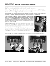
PLUMBING All valves are factory equipped with a short pipe nipple in their outlet. When attaching plumbing, hold
these nipples while tightening. Do not tighten plumbing by using a wrench on the brass valve bodies as
this can damage the valve! Brass or copper lines are recommended for all plumbing.
1. INSTALL WATER LINE
Run a ½” potable water feed line between the nearest cold water line and the WATER INLET fitting on the
generator. Cold feedwater is required for proper operation of the CoolFlush™ Auto Drain system. Special water
treatment may be required in your area – see Water Quality section on pages 7 and 8 for further details. Install a
shut-off valve near the generator. When tightening the water fittings, always use two wrenches so there will be no
strain on the water inlet valve. The water shut off valve must remain open during generator operation! We
recommend feedwater pressure between 138 and 690 kPa. A water hammer prevention device is installed on
your boiler. Excessive water hammer can damage a water valve, preventing it from shutting off the water supply
to the generator!
Flush water supply line thoroughly before final hookup. Debris such as flux residue can prevent the inlet valve
from fully closing and may cause corrosion damage to the water valve or heating elements. A grit filter is factory
installed at the water inlet to trap large debris such as sand. Shut the water supply off and remove and clean the
filter periodically as dictated by local water conditions.

4211-1641 05/30/19 Technical Support: 1-800-363-0251 [email protected] 11 of 29
9,5 mm FROM WALL
STEAM HEAD INSULATOR
STEAM HEAD FACE
FRAGRANCE
RESERVOIR
3/4” NPT: 40 mm
DIAMETER HOLE
STEAM PIPE FITTIN
G
A check valve is installed in the boiler’s feedwater line. An additional customer supplied back-flow prevention
device may be required in your area. Check local codes. To prevent water level sensing errors, backflow
prevention is necessary in installations where the steam generator’s water supply is shared with another
generator or other nearby high usage connection.
2. INSTALL STEAM LINE
AI generators come equipped with ¾”NPT steam outlets. Do not place a shutoff device in the steam line! Locate
steam heads so bathers do not come into contact with a steam head and so steam may not exhaust directly on
any part of a bather’s body. Steam and steam heads are very hot and can cause severe burns!
Run a ¾” copper steam line from the generator to the steam room. The steam line should enter the steam room
45mm above the floor.
IMPORTANT: The steam line should be pitched away from the generator so any condensate will drain from the
steam line. For best results, the generator should be installed as close to the steam room as possible, with its
steam outlet valve higher than the steam heads in the steam room and the steam line run straight to the steam
heads with a pitch of at least 20mm per meter to drain into the room. Do not allow sags, dips or other low
sections in the steam line: these may block the steam flow or cause spitting of very hot water into the steam
room.
As with any steam bath steam generator, spitting, reduced steam and other problems can occur if too many
elbows or tees are placed in the steam line, if the line is too long, if the line has large rises or if there are low area
or traps in the line. The effects depend on the number and size of these practices in a particular installation.
To reduce noise or improve the distribution of steam in larger rooms, additional steam heads may be installed.
Two steam heads are supplied with each generator. Space steam heads at 150mm intervals, minimum. The
steam heads should be located to ensure they do not discharge steam or drip condensate where the user may
come in contact with the hot moisture – contact may cause injuries from scalding to severe burns!
At the steam room: drill/prepare a 40mm hole at each steam head location for steam line entry 460mm above the
floor. Terminate the steam line from the generator with a tee at the steam room then plumb each side of the tee
to a steam head location and through the wall. Center the
3
/
4
” copper steam pipe in the 40mm hole. Terminate
the steam line with a
3
/
4
” NPT male adapter. Stub the line out into the room 9.5mm from the finished surface.
Secure the steam lines to structural members.
Install steam heads so vent opening is pointed
towards the floor. Use Teflon thread tape to help
aim the steam head correctly if necessary. Protect
the steam head finish from damage while handling
and tightening. Seal the wall around the steam
pipes and all fixtures in the steam room with 100%
silicone caulk to avoid moisture damage within the
walls.
IMPORTANT If the steam line is in an area where
the temperature will be below 4°C or if the line is more than 6 meters long, best results can be obtained by
insulating the steam pipe. Any insulation must be suitable for temperatures of at least 120°C.
Seal rear
Of insulator
With silicone
305mm min
150mm
305mm min
305mm min
450mm min

4211-1641 05/30/19 Technical Support: 1-800-363-0251 [email protected] 12 of 29
3. INSTALL SAFETY VALVE LINE All AI generators are equipped with a factory installed 103kPa pressure relief
safety valve. This must be plumbed to a ¾” indirect waste line. Do not install a shut off device in this line. Do not
reduce this line. Do not form a trap in this line! Discharge from the safety valve may be at over 115°C. Do not
plumb this line into the steam room! Plumb this waste line per local plumbing codes.
4. INSTALL DRAIN All
AI generators are equipped with a factory installed manual ball valve to allow draining the
tank. An optional electronic drain may be installed after the manual valve. Plumb the drain to a ¾” indirect waste
line. If the drain is opened while the generator is under pressure, discharge from the drain may be at over 115°C.
Always plumb the drain with piping suitable for 115°C minimum. Do not plumb this line into the steam room!
Plumb this waste line per local plumbing codes. When equipped with an Autodrain system and with the pressure
control properly set to 27 to 35 kPa, drain water will be at or below 60°C during the CoolFlush™ Auto Drain
cycle. Local codes may require a (customer supplied) expansion tank or blowdown cooling tank if draining water
in excess of 60°C or 35 kPa.
ELECTRICAL
Refer to the ID plate on the generator’s switch panel to determine voltage and current requirements. Electrical
service for all models requires 240V~N or 415V~N3 plus a suitable earth connection. Route the copper mains
wires with appropriate strain relief through the hole marked POWER ENTRIES. A multiple knockout is provided
at this point for electrical service using up to 2” conduit. A second knockout, ½” to ¾”, is provided, if needed.
415V~3
240V~N
EARTH
GROUND
240V~
N
L3
L2
L1
N
EARTH
G
ROUND
240V~
N
240V~
Connect the control circuit’s Neutral to the outside terminal of the small terminal block provided in the generator’s
electrical enclosure. Connect the power service to the generator’s large terminal block and earth to the
generator’s earth ground lug, located near the front edge of the electrical enclosure (a copper wire clamping lug
with green screw). Ensure all wires are tightly clamped at their respective terminals.
CAUTION: Loose wire connections can cause heat damage to wires, terminal blocks and other
components and may void the warranty.
NOTE: A GFCI device is not usually required. A GFCI may be installed if required by local codes or the owner. A
GFI device will tend to nuisance trip due to heater element aging.

4211-1641 05/30/19 Technical Support: 1-800-363-0251 [email protected] 13 of 29
ROOM CONTROLS
Each steam valve outlet is to be used for a single steam room. Each room requires one temperature sensor
mounted in the room and one thermostat control mounted outside the room. The thermostat mounts to a
standard single switch/outlet electrical box. The thermostat may be mounted directly on the generator’s electrical
enclosure using a common ½” conduit z-bracket between the box and a knockout provided in the generator’s
electrical enclosure. To reduce the risk of electrical interference between circuits, do not run the low voltage
control cables inside the same conduit as high voltage circuits. Avoid running control cables closely alongside
high voltage wiring in cable troughs and raceways.
05
Two independent control circuits are available with two steam outlets so the boiler can supply two separate
steam rooms. If only one valve is installed on the steam generator, it will be controlled by the ROOM 1 circuit with
controls connected to the terminal blocks alongside the upper left edge of the printed circuit board (PCA) located
in the generator’s electrical enclosure. When the (optional) second outlet is provided, the second room’s controls
connect along the lower left side of the circuit board in the same manner as the ROOM 1’s circuit’s described
here..
1. TEMPERATURE SENSOR INSTALLATION The temperature sensor must be mounted in the steam room. Cut
a 22mm diameter hole in the steam room wall to mount the sensor. It is recommended that the sensor be
mounted 150mm down from the ceiling, but not directly over the steam dispersion head and not more than 2,1 M
above the floor. Do not cover or enclose the sensor: if the airflow across the sensor is blocked or reduced, the
room may overheat or suffer large temperature variations.
A 7,6 M cable is provided for the sensor. String the sensor cable
from the sensor location through 13mm
holes in the wall studs or
ceiling joists to the generator location. Leave 30mm of slack at the
sensor location. Route the generator end of the sensor cable
through the generator hole marked CONTROL WIRING ENTRY
using the strain relief provided.
Note: Do not staple through or otherwise damage the cable. Use a
factory supplied sensor cable only.

4211-1641 05/30/19 Technical Support: 1-800-363-0251 [email protected] 14 of 29
INSTALL ONLY IN A DRY LOCATION
FOR SERVICE CALL: 1-800-363-0251
Saunatec Inc.
P.O. Box 2258
Woodinville, WA 98072
BLACK WIRE
RED WIRE
WHITE WIRE
5
6
ROOM TEMPERATURE
7
8
9
10
4
3
OFF
2
1
BATH
STEAMBATH
ON
CABLE TO
TEMPERATURE SENSOR
In the steam room: Plug the temperature sensor into the sensor cable. The cable and the sensor connectors are
designed to lock together when properly aligned. Run a bead of 100% silicone caulk around the underside of the
sensor head then carefully feed the cable and sensor through the hole and attach the sensor in place.
At the generator: Connect the sensor cable’s end plug into its socket on the generator’s control circuit board. The
socket is directly above the room’s T’STAT terminal block. Orient the cable end to match its socket and insert it
until the end locks in place. Make sure the thermostat and temperature sensor cables are connected at the same
side of the circuit board: either along the left edge (ROOM 1) or the right (ROOM2). When only one steam outlet
valve is available, always connect to ROOM 1.
2. THERMOSTAT INSTALLATION The low voltage thermostat control can be mounted up to 15 M from the
generator and must be located outside the steam room. A 7,6 M cable is provided. String the 7,6 M cable from
the control location through ½” holes in the wall studs or ceiling joists to the generator and the switch box
installed at the desired control mounting location. An
IT1 is always required for each room.
At the control: Connect the control cable to the thermostat control using wire nuts (provided). Match the provided
cable’s red and black wires to the thermostat’s red and black wires, respectively. Match the cable’s third wire
(white or green) to the thermostat’s white wire.
At the generator: Route the generator end of the control
cable through the generator hole marked CONTROL
WIRING ENTRIES using the strain relief provided. Strip the
control cable wire ends 13mm and place the bare copper
into the ROOM 1 (or ROOM 2) T’STAT terminal block,
putting the black wire in the bottom hole (“3”), red in the
center (“2”) and white (or green) in the top (“1”). Use a small
screwdriver to carefully press the terminal block’s orange
tabs down to insert or remove the wire ends. When only one
steam outlet valve is installed, always connect to ROOM 1.
The thermostat has an integral switch to start and stop the heating of the steam room: see operating instructions.
If an (optional)
I60 switch or other switch is to be used, it will connect to the ROOM SWITCH terminal block as
described in the following section. When using the thermostat as the Bath on/off switch, all positions of the boiler
circuit board’s switch must be set down (the switch is located near the upper the center of the PCA).
3. ROOM SWITCH INSTALLATION The (optional)
I60 switch is a momentary switch (closed only while
pressed) intended for installations with occasional use. When an I60 switch or equivalent is connected, the
circuit board’s switch must be correctly set as shown below. The steam bath will start when the switch is pressed
and stop when the switch is pressed again or stop automatically at the bath time selected using the switch.
The
I60 may be mounted up to 15 M from the generator and must be located outside the steam room. A 7,6 M
cable is provided. String the 7,6 M cable from the control location through 13mm holes in the wall studs or ceiling
joists to the generator and the switch box installed at the desired control mounting location.
If the optional second steam room is installed, both rooms must use the same type of on/off switch,
either the thermostat or the
I60!
OPTIONAL To use a timer control on/off switch as a Room Switch (supplied by user), be sure it is capable of
switching a 3VDC circuit. Connect the switch contacts to positions 1 and 2 of the Room Switch terminal block
and set the circuit board’s switch to position 1 up (room switch control, no time out). This will not work with a
momentary switch.
Thermostat
On/Off
RoomSwitch
No Bath Timer
15 Minutes
Bath Time
30 Minutes
Bath Time
60 Minutes
Bath Time
ON
ON
1234 1234 1234 1234
ON
ON
1234
ON
When using the I60

4211-1641 05/30/19 Technical Support: 1-800-363-0251 [email protected] 15 of 29
Saunatec Inc.
INSTALL ONLY IN A DRY LOCATION
FOR SERVICE CALL: 1-800-363-0251
P.O. Box 2258
Woodinville, WA 98072
STEAMBATH
ON/OFF
BATH
ON
RED WIRE
WHITE WIRE
BLACK WIRE
CABLE TO THERMOSTAT
CABLE TO TEMPERATURE SENSOR
1
3
2
CABLE TO TEMPERATURE SENSOR
CABLE TO THERMOSTAT
BLACK WIRE
WHITE WIRE
RED WIRE
At the I60: Connect the control cable to the switch using wire nuts (provided). Match the provided cable’s red
and black wires to the switch’s red and black wires, respectively. Match the cable’s third wire (white or green) to
the switch’s white wire.
At the generator: Route the generator end of the switch cable
through the generator hole marked CONTROL WIRING ENTRY
using the strain relief provided. Strip the control cable wire ends
13mm and place the bare copper into the ROOM 1 (or ROOM 2)
ROOM SWITCH terminal block, putting the black wire in the bottom
hole (“3”), red in the center (“2”) and white (or green) in the top (“1”).
Use a small screwdriver to carefully press the terminal block’s
orange tabs down to insert or remove the wire ends. When only one
steam outlet valve is installed, always connect to ROOM 1.
4. REFRESH SWITCH INSTALLATION The (optional) Refresh™ switch uses a low voltage control to provide a
short burst of steam into the steam room when the switch is pressed. The switch may be mounted up to 15 M
from the generator and must be located inside the steam room. A 7,6 M cable is provided. String the 7,6 M cable
from the control location through 13mm holes in the wall studs or ceiling joists to the generator and the desired
control mounting location in the steam room.
At the control: Connect the control cable to the switch terminal block on the Refresh™
switch. Connect the switch cable to the switch and note which wire is connected to which
terminal block position. An instruction plate is provided and should be attached to the wall
alongside the Refresh™ switch in the steam room to help bathers understand the
Refresh™ operation. The instruction plate is adhesive backed for easy mounting to a clean
dry surface.
At the generator: route the generator end of the switch cable through
the generator hole marked CONTROL WIRING ENTRIES using the
strain relief provided. Strip the switch cable wire ends 13mm and
place the bare copper into the ROOM 1 (or ROOM 2) REFRESH
SWITCH terminal block, matching the colors to the terminal block
positions identically to the switch’s connections. When finished, the
switch’s block position 1 should be connected to the PCA’s position
1, 2 to 2 and 3 to 3. Use a small screwdriver to carefully press the
terminal block’s orange tabs down while inserting or removing the
wire ends. When only one steam outlet valve is installed, always
connect to ROOM 1.
Note: In areas with high humidity or a high chlorine or chemical environment, such as around pool treatment
equipment, we recommend adding some dielectric grease to low voltage wire connections to reduce the risk of
corrosion.

4211-1641 05/30/19 Technical Support: 1-800-363-0251 [email protected] 16 of 29
HE AT CON TAC TORS
BOILER ON
LIGH T
ROOM 2 CONTROLSAND STEAM VALVE
ARE OPTIONAL AND MAY NOT BE I NSTALLED
GND
N
MANUAL
RUN
BOILER
OPERATION
RUN CLOCK
(OPTION)
M
CLOCK
RUN
STEAM VALVE
OPEN L IGHT
M
AUTODRAIN CLOCK
(OPTION)
3241-051
PRINTED
CIRCUIT BOARD
MANUAL OPEN
ROOM
STATUS
LEDS
ROOM1 LOCKOUT
ROOM2 LOCKOUT
NORMA L
ROOM -1
RELAY
ROOM-2
RELAY
HEAT
RELAY
FEEDWATER
RELAY
STOP FILL
OFF
HEAT
STM
STEAM VALVE
OPEN LIGHT
STM
CLOSE V A LVE
NORMA L
WATER VALVE
OPEN L IGHT
CLOSE V A LVE
NORMA L
ROOM 2
STEAM
OUTLET
SOLENOID
ROOM 1
STEAM
OUTLET
SOLENOID
FEEDWATE R
SOLENOID
BOILER
HEATING LIGHT
NORMA L
OFF
H 0
2
PRESSURE
SWITCH 2
PRESSURE
SWITCH 1
LWCO
RELAY
TEST
RESET
LWC O STATU S LED
RM1
RD1
RM2
RD2
LWC O TEST
LWCO RESET
LWCO LED
240V
ELEMEN T
ASSEMB LY
1 2 3
230-240V~ N1
ON
STEAMBATH
ON
STEAMBATH
LEVE L PROBES
WATER ON
WATER OFF
HE AT OK AY
ON/OFF
ON/OFF
BATH
29
ON/OFF
10
7
ROOMTE MP E RATURE
9
8
4
56
1
ON
OFF
BATH
2
3
STEAMBATH
7
ROOMTE MP E RATURE
8
ON/OFF
4
56
3
BATH
10 1
ON
BATH
OFF
STEAMBATH
L
(OPTIONAL)
ROOM SWITCH
T'STAT
TEMP SENSOR
AU TO-LWCO
MANUA L
LWCO
HEAT
RM1
RM2
WATER
CONTROL
CIRCUIT
FUSE
3AMP
NONTIME
DELAY
NEUT
LINE
GND
R
D
H
M
L
DRAIN
RELAY
DRAIN
STEAM VALVE
OPEN LIGHT
ELECTRONIC
DRAINVALVE
(OPTION)
(OPTIONAL)
REFRESH
SWITCH
M
(OPTIONAL)
FRAG PUMP
T'STAT
TEMP SENSOR
(OPTIONAL)
ROOM SWITCH
(OPTIONAL)
REFRESH
SWITCH
(OPTIONAL)
FRAG PUMP
ROOM1
ROOM2
OPEN ON RISE
DRAIN
CLOCK
N
230-240V
WIRING: Control Circuit, All Models 240V~N
ALL WIRING MUST BE INSTALLED BY A LICENSED ELECTRICAL CONTRACTOR IN ACCORDANCE
WITH ALL APPLICABLE LOCAL AND NATIONAL CODES.
ELECTRIC SHOCK HAZARD – HIGH VOLTAGE EXISTS WITHIN THIS EQUIPMENT. THERE ARE NO USER SERVICEABLE PARTS IN
THIS EQUIPMENT.
ELECTRICAL GROUND REQUIRED ON ALL STEAMERS.
DISCONNECT ALL ELECTRICAL SUPPLIES WHEN SERVICING THIS EQUIPMENT.

4211-1641 05/30/19 Technical Support: 1-800-363-0251 [email protected] 17 of 29
BOILER ON
LIGH T
ROOM 2 CONTROLSAND STEAM VALVE
ARE OPTIONAL AND MAY NOT BE INSTALLED
GND
N
MANUAL
RUN
BOILER
OPERATION
RUN CLOCK
(OPTION)
M
CLOCK
RUN
STEAM VALVE
OPEN LIGHT
M
AUTODRAIN CLOCK
(OPTION)
3241-051
PRINTED
CIRCUIT BOARD
MANUAL OPEN
ROOM
STATUS
LEDS
ROOM1 LOCKOUT
ROOM2 LOCKOUT
NORMA L
ROOM-1
RELAY
ROOM-2
RELAY
HEAT
RELAY
FEEDWATER
RELAY
STOP FILL
OFF
HEAT
STM
STEAM VALVE
OPEN L IGHT
STM
CLOSE VA LVE
NORMA L
WATER VALVE
OPEN LIGHT
CLOSE VA LVE
NORMA L
ROOM 2
STEAM
OUTLET
SOLENOID
ROOM 1
STEAM
OUTLET
SOLENOID
FEEDWATE R
SOLENOID
BOILER
HEATING L IGH T
NORMA L
OFF
H 0
2
PRESSURE
SWITCH 2
PRESSURE
SWITCH 1
LWCO
RELAY
TEST
RESET
LWCO STATU S LED
RM1
RD1
RM2
RD2
LWCO T EST
LWCO RESET
LWCO LED
240V
ON
STEAMBATH
ON
STEAMBATH
LEVE L PROBES
WATER ON
WATER OFF
HE AT OK AY
ON/OFF
ON/OFF
BATH
29
ON/OFF
10
7
ROOMTEMPE RATU R E
9
8
4
56
1
ON
OFF
BATH
2
3
ST E A MB ATH
7
ROOMTEMPE RATU R E
8
ON/OFF
4
56
3
BATH
10 1
ON
BATH
OFF
ST E A MB ATH
L
(OPTIONAL)
ROOM SWITCH
T'STAT
TEMP SENSOR
AU TO-LWCO
MANUA L
LWCO
HEAT
RM1
RM2
WATER
CONTROL
CIRCUIT
FUSE
3AMP
NONTIME
DELAY
NEUT
LINE
GND
R
D
H
M
L
DRAIN
RELAY
DRAIN
STEAM VALVE
OPEN L IGHT
ELECTRONIC
DRAINVALVE
(OPTION)
(OPTIONAL)
REFRESH
SWITCH
M
(OPTIONAL)
FRAG PUMP
T'STAT
TEMP SENSOR
(OPTIONAL)
ROOM SWITCH
(OPTIONAL)
REFRESH
SWITCH
(OPTIONAL)
FRAG PUMP
ROOM1
ROOM2
OPEN ON RISE
DRAIN
CLOCK
HE AT CON TAC TORS
ELEMEN T
ASSEMB LY
1 2
3
400-415V~3
L3
L2
L1
WIRING: Contactor and Power wiring, All Models 415V~N
ALL WIRING MUST BE INSTALLED BY A LICENSED ELECTRICAL CONTRACTOR IN ACCORDANCE
WITH ALL APPLICABLE LOCAL AND NATIONAL CODES.
ELECTRICAL GROUND REQUIRED ON ALL STEAMERS.
ELECTRIC SHOCK HAZARD – HIGH VOLTAGE EXISTS WITHIN THIS EQUIPMENT.
THERE ARE NO USER SERVICEABLE PARTS IN THIS EQUIPMENT.
DISCONNECT ALL ELECTRICAL SUPPLIES WHEN SERVICING THIS EQUIPMENT.

4211-1641 05/30/19 Technical Support: 1-800-363-0251 [email protected] 18 of 29
STARTING THE GENERATOR FOR THE FIRST TIME
Before applying power to the generator for the first time: On the electrical box’s front panel set all rocker switches to
the left, their normal operating position. If installed, set the optional Run Clock so the generator is off (no orange
showing in area above pointer) and make sure the water supply is connected to the generator and turned on.
Open the valves on the glass water gauge all the way (counterclockwise).
Open the pressure gauge valve (handle horizontal). or
If the CoolFlush™ Auto Drain option is not installed, close the manual
drain (handle up).
If the optional electronic CoolFlush™ Auto Drain is installed, open
the manual drain ball valve as shown (handle pointing towards
electronic valve). Set the Drain Clock to an off position (no orange
showing in area above pointer).
Set the room thermostat(s) to the
OFF position.
Turn on the electrical service to the boiler. All lights and valves should be off at this point.
Set the
BOILER OPERATION switch to the right (red showing) or set the optional run clock to a “RUN” position.
The BOILER ON light, both room STEAM VALVE OPEN lights and the WATER VALVE OPEN light should turn on
and the boiler will start filling with water. The water will become visible in the water gauge a short time later.
The LWCO LED should be yellow or amber then change to green once the mid water level is reached. When the
maximum water level is reached, the feedwater valve and its light will turn off and the steam valve lights will turn
off, the
BOILER HEATING light will turn on and the heating element contactors will close. The boiler will continue
heating until it reaches its operating pressure of approximately 55 kPa then the BOILER HEATING light and the
contactors will turn off. During normal operation, the water level should always be visible in the lower half of the
gauge glass. If it drops to less than 13mm of water, the manual reset LWCO may alarm and shut the boiler down
until serviced.
Check for steam and water leaks. Repair any leaks before continuing.
NOTE: When the boiler is started with an empty tank, the room steam valves will open to release the air pressure
created during water fill. Once the tank has filled, the valves will operate normally, opening only when steam
needs to be released to a room to increase its temperature. Also, whenever a steam valve opens to release
steam to a room, the boiler heating is disabled for a few seconds. This is designed to increase the elements’
working life.
Turn the thermostat(s) on to begin heating the steam room(s). If an (optional)
I60 room switch is installed, set
the thermostat to the desired temperature and press the
I60 switch to start the steam bath and begin heating
the room. The status LEDs on the thermostat(s), switches and boiler will light and remain on continuously when
the steam bath is on and operating normally.

4211-1641 05/30/19 Technical Support: 1-800-363-0251 [email protected] 19 of 29
OPERATING INSTRUCTIONS The AI model steam generators are based on two operating systems. The first is
the generator itself, maintaining water levels and boiling the water to create steam for use in a steam bath. The
second is the steam room control circuit, maintaining a comfortable steam bath by releasing steam from the
generator only when needed to raise the temperature in the steam room. The generator’s control circuit board is
used for both systems so the generator must be running before starting a steam bath. And the generator may run
continuously without affecting the steam room temperature when the bath is off. In this way the generator can be
left running so it is ready to provide steam immediately when the thermostat (or optional
I60 room switch) is
used to start a steam bath.
BOILER START (RUN) The generator operation may be started in one of two ways.
1. MANUAL RUN To start the generator manually, place the BOILER OPERATION switch (located on the
generator’s switch panel) to its MANUAL RUN position. The switch will show a red color at its left side to
indicate that it has been turned on and the BOILER ON light will turn on to show the generator is running. If an
optional Run Clock is installed, this manual switch will start the generator regardless of the clock setting and
the generator will continue to run until the switch is returned to the CLOCK RUN position.
2. CLOCK RUN To start the generator using the optional Run Clock, leave the
BOILER OPERATION switch in its
CLOCK RUN position. Program the Run Clock to the desired on (RUN) and off periods. If the clock is switching
properly, when an on period is reached the
BOILER ON light will turn on and the generator will fill and heat as
necessary. Check the Run Clock later in the day to ensure it is maintaining time correctly. See clock
attachments for further details.
Normal RUN operation controls water fill and heating using three water levels. The lowest level serves as a low
water cut-off safety level: if the water level drops too far the heating elements are turned off to prevent damage.
When the water level is at the mid-level, there is enough water in the tank to allow heating it safely. When the
water level reaches top level (just above mid-glass) the water level has reached its maximum depth and the
water valve will close until the level drops to the mid-level again. If the water takes too long to fill, the mid-level
may turn off heating using its automatic resetting LWCO. If the level continues to drop during normal operation,
the boiler will go into a LWCO error and shut down completely about 10 seconds after the low level becomes dry.
Also see page 22 for more LWCO information.
Water heating is controlled by the operating pressure switch. While there is enough water in the tank to allow
heating, the elements will be energized if the pressure in the tank is below the switch setting (about 28 kPa) and
the water will be heated until enough steam pressure is generated to build up pressure in the tank to about 55
kPa. At this point the elements are turned off until the pressure drops again.
If the steam bath is not turned on, no steam will be released to the room and the generator will need to heat the
water only to make up for temperature loss from the generator itself. During a steam bath, particularly during
initial heating, the generator may need to heat continuously to compensate for the steam being released to the
steam room. The generator might not build up any pressure during this period.
When the generator is started with an empty tank, the steam outlet valve(s) will open to release air pressure
created by adding water. If not released, this air pressure could be sensed by the pressure switch, preventing
heating. When the water reaches its maximum depth, the heat will turn on, the water valve will close and, if the
steam bath is not turned on, the steam room valve(s) will close.
STEAM ROOM OPERATION (BATH) The steam room begins heating when the thermostat or
room switch is used to “turn on” the steam bath. While the steam bath is on, steam is released to
the room as needed to bring the temperature up to the thermostat setting. When the generator
supplies two rooms, the room operations are identical but independent. Only the use of one
room will be described here.
The thermostat sets the room temperature using a 1 to 10 scale, with 1 being the coolest at
about 32°C and 10 the hottest at about 51°C. These are the steam room temperatures sensed
by the temperature sensor near the ceiling. For bather safety and to prevent damage to the
steam room, never attempt to force these temperatures higher!

4211-1641 05/30/19 Technical Support: 1-800-363-0251 [email protected] 20 of 29
LWCO
RESET
STATUS
TEST
6D07 2018
THE THERMOSTAT has an OFF position to turn the steam bath off (prevent heating) if an I60 switch option is
not installed. When the bath is turned off, the generator’s steam valve will remain closed and the thermostat’s
LED, the Refresh™ switch’s LED and their corresponding ROOM STATUS LEDs on the generator will remain
turned off. When the thermostat is turned to the temperature setting part of the dial, the steam bath is turned on
and all of the corresponding LEDs will light.
For the steam bath to be on whenever the generator is running, leave the thermostat set to the desired
temperature setting. Soon after the generator is started, the room’s LEDs will light and it will begin heating as
soon as steam is available. Do not install an
I60 option when using continuous operation.
THE
I60 SWITCH option is intended for steam rooms with only intermittent use. When the I60
is installed, the thermostat’s off position is the same as the lowest temperature setting and has no
effect on the generator operation. The generator runs, holding steam under pressure until the
user is ready to start a steam bath. The thermostat should be left preset to the desired room
temperature. Press the
I60 to start the steam bath. The room’s LEDs will light once the bath is
started. To stop the steam bath, press the
I60 switch again or wait and it will turn off
automatically at its pre-set time (15, 30 or 60 minutes – See page 14). If the generator supplies
two rooms, both must use the same type of switch: if one uses an
I60 switch the other must as
well.
THE REFRESH™ SWITCH option gives the bather a more immediate control over the steam bath conditions. By
pressing the Refresh™ switch during a steam bath, an extra burst of steam is added to the room regardless of
the steam room temperature. This may be used to compensate for sudden cooling caused by someone opening
the steam room door, for instance. An LED on the Refresh™ switch lights to indicate that the steam bath is
turned on and an extra burst of steam is available. Once the switch is pressed, the switch’s LED turns off and
steam is released to the room for about 10 seconds. The extra steam released to the room adds a little heat and
steam to “refresh” the steam cloud and stir the room’s air, helping to reduce cold spots. There is a 2 minute delay
after the Refresh™ switch is pressed before its LED turns on again and another steam burst is available. This
wait period is designed to prevent a bather from accidentally overheating the room. Generally, if the room has
cooled enough to need a second Refresh™ burst it will have cooled enough to require normal heating, too.
LIGHTS AND SWITCHES are provided to show generator operating status, to indicate
fault conditions and to allow manual control of generator functions for routine
maintenance and troubleshooting. During normal steam bath operation, the
ROOM
STATUS LEDs on the generator will light steadily. When the optional Refresh™ switch is
installed, the bottom room status LED will turn off for two minutes while Refresh™ is in
use. These LEDs will blink in specific patterns to indicate problems with the steam bath
temperature control, generator water level control or drain flow (with the Autodrain
installed).
When the generator is operating normally, the
BOILER ON light will be lit. All switches will
be set to the left except the BOILER OPERATION switch will be set to MANUAL RUN (unless
an optional Run Clock is installed).
The generator’s
STEAM VALVE OPEN lights will turn on when steam is released to heat
the corresponding steam room. Set a room’s ROOM LOCKOUT switch to the CLOSE VALVE
position to prevent steam being released to that room during servicing, room cleaning,
etc.
Whenever the generator is operating, the contactors will close as needed to turn on the
heating elements, heating the generator’s water and creating steam. The
BOILER
HEATING light turns on when the elements are turned on. Place the HEAT switch in the
OFF position to prevent heating, such as during manual drain/blowdown. NOTE:
whenever a steam valve opens to release steam to a room, the boiler heating is disabled
for a few seconds. This is designed to increase the elements’ working life.
/