Page is loading ...

DS05(03)
DS05(04)
DS05(07)
DS05(14)
DS05(15)
DS1
DS1(04)
DS1/T
Instruction Manual
turboSPEED DZ140

MICRO-EPSILON
MESSTECHNIK
GmbH & Co. KG
Königbacher Strasse 15
94496 Ortenburg / Germany
Tel. +49 (0) 8542 / 168-0
Fax +49 (0) 8542 / 168-90
e-mail [email protected]
www.micro-epsilon.com
Certified according to DIN EN ISO 9001: 2008
Speed measuring system for turbo chargers

turboSPEED DZ140
Contents
1. Safety ........................................................................................................................................................ 5
1.1 Symbols Used ................................................................................................................................................. 5
1.2 Warnings .......................................................................................................................................................... 5
1.3 Notes on CE Identification ............................................................................................................................... 6
1.4 Proper Use ....................................................................................................................................................... 6
1.5 Proper Environment ......................................................................................................................................... 7
2. Functional Principle, Technical Data ....................................................................................................... 8
2.1 Applications ..................................................................................................................................................... 8
2.2 Functional Principle ......................................................................................................................................... 8
2.3 Structure of the Complete Measuring System ................................................................................................ 8
2.4 Technical Data ................................................................................................................................................. 9
3. Delivery ................................................................................................................................................... 11
3.1 Unpacking ...................................................................................................................................................... 11
3.2 Storage .......................................................................................................................................................... 11
4. Mounting ................................................................................................................................................. 12
4.1 Sensor ............................................................................................................................................................ 12
4.2 Sensor Cable ................................................................................................................................................. 15
4.3 Supply and Signal Cable ............................................................................................................................... 15
4.4 Controller DZ140............................................................................................................................................ 16
4.5 Electrical Connections ................................................................................................................................... 17
4.5.1 Supply, Outputs ............................................................................................................................ 17
4.5.2 Power Supply ............................................................................................................................... 18
4.5.3 RAW SIGNAL ................................................................................................................................ 20
4.5.4 Ground Concept ........................................................................................................................... 20

turboSPEED DZ140
5. Operation ................................................................................................................................................ 22
5.1 Connecting the Measuring System ............................................................................................................... 22
5.2 LEDs on the Controller .................................................................................................................................. 23
5.3 Positioning of the Sensor .............................................................................................................................. 24
5.3.1 Open Turbine Chamber ................................................................................................................ 24
5.3.2 Closed Turbine Chamber ............................................................................................................. 24
5.4 Test Signal ...................................................................................................................................................... 25
5.5 Settings .......................................................................................................................................................... 26
5.5.1 Mode (Turbo Charger Speed, Sensitivity, Test Signal) ............................................................... 26
5.5.2 Number of Blades......................................................................................................................... 27
5.6 Analog Output ............................................................................................................................................... 28
5.7 Sensor Temperature ...................................................................................................................................... 29
6. Troubleshooting ...................................................................................................................................... 31
7. Warranty .................................................................................................................................................. 33
8. Service, Repair ....................................................................................................................................... 33
9. Decommissioning, Disposal ................................................................................................................. 33
Appendix
A 1 Optional Accessories ............................................................................................................................. 34
A 2 Labels on Rear Side of Controller for Printing...................................................................................... 35

Page 5
Safety
turboSPEED DZ140
1. Safety
The handling of the system assumes knowledge of the instruction manual.
1.1 Symbols Used
The following symbols are used in this instruction manual.
CAUTION
Indicates a hazardous situation which, if not avoided, may result in minor or mode-
rate injuries.
Indicates a situation which, if not avoided, may lead to property damage.
Indicates a user action.
i
Indicates a user tip.
Measure
Indicates a hardware or a button/menu in the software.
1.2 Warnings
Connect the power supply and the display / output device in accordance with the safety regulations for elec-
trical equipment.
> Danger of injury
> Damage to or destruction of the sensor and / or controller
The power supply must not exceed the specified limits.
> Danger of injury
> Damage to or destruction of the sensor and / or controller
Avoid shock and vibration to the sensor and / or controller.
> Damage to or destruction of the sensor and controller
Protect the sensor cable against damage
> Failure of the measuring device
NOTICE
CAUTION
NOTICE

Page 6
Safety
turboSPEED DZ140
1.3 Notes on CE Identification
The following applies to the turboSPEED DZ140:
- EU directive 2014/30/EU
- EU directive 2011/65/EU, “RoHS” category 9
Products which carry the CE mark satisfy the requirements of the EMC directives and the standards (EN)
listed therein.
The EC declaration of conformity is kept available according to EC regulation, article 10 by the authorities
responsible at
MICRO-EPSILON MESSTECHNIK GmbH & Co. KG
Königbacher Str. 15
94496 Ortenburg / Germany
The system is designed for use in industry and satisfies the requirements.
1.4 Proper Use
- The system is designed for use in industrial areas.
- It is used for speed measurement on turbo chargers.
- The system may only be operated within the limits specified in the Technical Data, see Chap. 2.4.
Use the system in such a way that in case of malfunctions or failure personnel or machinery are not
endangered.
Take additional precautions for safety and damage prevention for safety-related applications.

Page 7
Safety
turboSPEED DZ140
1.5 Proper Environment
- Protection class controller: IP 65
- Operating temperature
Sensor: -40 ... +285 °C (-40 ... +545 °F)
Sensor cable: -40 ... +200 °C (-40 ... +392 °F)
Controller: -40 ... +125 °C (-40 ... +257 °F) (at max. 15 VDC power supply)
1)
- Storage temperature
Sensor, sensor cable: -40 ... +200 °C (-40 ... +392 °F)
Controller: -40 ... +125 °C (-40 ... +257 °F)
- Humidity: 5 - 95 % (non-condensing)
- Ambient pressure: atmospheric pressure
- Supply: 9 ... 30 VDC / briefly 36 VDC / max. 50 mA
1)
If power supply is higher, the max. acceptable ambient temperature decreases, see Fig. 14.

Page 8
Functional Principle, Technical Data
turboSPEED DZ140
2. Functional Principle, Technical Data
2.1 Applications
The non-contacting compact revolution counter is designed for industrial application for turbo charger moni-
toring on test benches and for measurements during driving tests.
2.2 Functional Principle
A very fast proximity sensor responds to turbo charger blades (depending on initial state) made of electrically
conducting materials passing by. The eddy current loss principle effects impedance changes in a measuring
coil (sensor). This change of impedance gives rise to an electric signal.
2.3 Structure of the Complete Measuring System
The non-contacting single-channel measuring system consists of:
- Sensor and sensor cable
- Controller (installed in a compact aluminum housing)
- Power supply and signal cable, see Chap. 4.3
Individual components of the measuring system can be changed without limiting the functionality.
turboSPEED
Remote
Status
SENSOR
SUPPLY /
OUTPUT
Mode
RAW SIGNAL
Blades
Sensor Controller
1
2
3
4
5
6
7
8
9
10
11
12
13
14
15
16
Fig. 1 Components for speed measurement

Page 9
Functional Principle, Technical Data
turboSPEED DZ140
2.4 Technical Data
Model DZ140 (Controller)
Sensors DS05(03) DS05(04) DS05(07) DS05(14) DS05(15) DS1 DS1(04) DS1/T
Measuring principle /
Target (blade material)
eddy current principle / aluminum or titanium
Maximum speed range (measuring range) 200 ... 400,000 RPM
Operating
temperature
Controller -40 ... +125 °C
1)
, -40 ... +257 °F
Sensor -40 ... +235 °C, -40 ... +455 °F (short-term +285 °C, +545 °F)
Sensor cable -40 ... +200 °C, -40 ... +392 °F
Integral sensor cable 0.5 m ±0.15 m 0.75 m ±0.15 m 0.8 m ±0.15 m
Number of blades rotary switch (accessible from the outside) for 1 up to 16 blades
Digital output
1 pulse / blade (switch Blades on 1, TTL level, variable pulse duration) or
1 pulse / revolution (switch Blades on 2...16, TTL level with 100 µs pulse duration)
Analog output
Mode 1, 3, 5: 0 ... 5 V (200 ... 200,000 rpm)
Mode 0, 2, 4: 0 ... 5 V (200 ... 400,000 rpm)
mode rotary switch, adjustable, accessible from outside
Sensor temperature output (analog) 0 ... 5 V (-50 ... +300 °C)
RAW signal
Analog measurement signal to control distance between sensor and blade by means of
an oscilloscope, see Fig. 20;
load resistance > 5 kOhm, load capacity max. 1 nF
Output sensor temperature 0 ... 5 V (-50 ... +300 °C, -58 ... +572 °F)
Power supply 9 V ... 30 VDC / max. 50 mA (short-term up to 36 VDC)
1)
If power supply is higher, the max. acceptable ambient temperature decreases, see Fig. 17.

Page 10
Functional Principle, Technical Data
turboSPEED DZ140
Model DZ140 (Controller)
DS05(03) DS05(04) DS05(07) DS05(14) DS05(15) DS1 DS1(04) DS1/T
Storage temperature
Sensor,
sensor cable
-40 ... +200 °C, -40 ... +392 °F
Controller -40 ... +125 °C, -40 ... +257 °F
Cable
PC140-3 supply and output cable 3 m
PC140-6 supply and output cable 6 m
PC140-8 supply and output cable 8 m
Weight Controller DZ140: appr. 92 g
Protection class Controller DZ140: IP 65
FSO = Full Scale Output

Page 11
Delivery
turboSPEED DZ140
3. Delivery
3.1 Unpacking
1 Controller DZ140
1 Protection cover for the
RAW SIGNAL output
1 Instruction manual
1 Multi corrugated spring
Separately available:
Sensor DSx or Sensor DSx/T including integrated sensor cable
Versorgungs- und Signalkabel PC140-x, see Chap. 4.3.
Check the delivery for completeness and shipping damages immediately after unpacking.
In case of damages or missing parts, please contact the manufacturer or supplier.
You will find further optional accessories in appendix, see Chap. A 1.
3.2 Storage
- Storage temperature:
Sensor and sensor cable: -40 ... +200 °C (-40 ... +392 °F)
Controller: -40 ... +125 °C (-40 ... +257 °F)
- Humidity: 5 - 95 % (non-condensing)

Page 12
Mounting
turboSPEED DZ140
4. Mounting
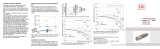
4.1 Sensor
35 (1.38)
18 (0.71)
45°
±3°
ø 3
(0.12 dia)
WS4
appr. 9,5
(0.37)
Sensor cable
ø approx. 3.5 mm
Length 0.5 m (±0.15 m)
with BNC connector
Fig. 2 Dimensional drawing DS05(03)
66
(2.60)
ø 3
(0.12 dia.)
WS4
appr. 9,5
(0.37)
Sensor cable
ø approx. 3.5 mm
Length 0.5 m (±0.15 m)
with BNC connector
Fig. 3 Dimensional drawing DS05(04)
Measuring
direction

Page 13
Mounting
turboSPEED DZ140
ø 3
(0.12)
46
(1.81)
66
(2.60)
1 (0.04)
M5
WS4
appr. 9,5
(0.37)
ø 3 (0.12 dia.)
Sensor cable
ø approx. 3.5 mm
Length 0.5 m (±0.15 m)
with BNC connector
Fig. 4 Dimensional drawing DS05(07)
M5
28
(1.10)
appr. 9 5
(0.37)
WS4
Sensor cable
ø approx. 3.5 mm
Length 0.5 m (±0.15 m)
with BNC connector
Fig. 5 Dimensional drawing DS05(14
45
(1.77)
M5
WS4
appr. 9,5
(0.37)
Sensor cable
ø approx. 3.5 mm
Length 0.5 m (±0.15 m)
with BNC connector
Fig. 6 Dimensional drawing DS05(15)

Page 14
Mounting
turboSPEED DZ140
M5x0.5
40
(1.57)
WS4
appr. 9,5
(0.37)
Sensor cable
ø approx. 3.5 mm
Length 0.75 m (±0.15 m)
with BNC connector
Fig. 7 Dimensional drawing DS1
M5x0.5
approx. 9.5
(.37)
40 (1.57)
Sensor cable ø approx. 4.5 mm
Kabellänge 0.8 m (± 0.15 m)
with triax-BNC-connector
ø approx.
19 (.75)
Sensor cable with 2 shields
(triax cable)
ø approx. 5 mm
Length 0.8 m (±0.15 m)
with triax cable socket
Fig. 8 Dimensional drawing DS1/T
M5x0.5
42
(1.65)
WS6
Sensor cable with metal protec-
tion hose
stainless steel IP 40
ø appr. 6.0; cable length 0.8 m
(± 0.15 m)
with BNC-connector
Fig. 9 Dimensional drawing DS1(04)
Dimensions in mm (inches), not to scale
Measuring
direction

Page 15
Mounting
turboSPEED DZ140
4.2 Sensor Cable
Mount the sensor cable in such a way that the cable sheath is not exposed to any sharp-edged or heavy
objects. Do not kink the cable.
i
Never come below the proper bending radius of the sensor cable:
10 x diameter in the case of dynamic application,
5 x diameter in the case of static application.
Make sure that the plug connectors at the sensor and at the controller fit tightly.
i
As the capacity and the adjustment of the measuring system change, please do not shorten the
matched sensor cables.
4.3 Supply and Signal Cable
i
Never come below the proper bending radius of the supply and signal cable:
7.5 x cable outer diameter.
Fig. 10 Supply and signal cable, 3, 6 or 8 m long

Page 16
Mounting
turboSPEED DZ140
4.4 Controller DZ140
The controller DZ140 is installed in an aluminum housing. The controller demodulates and amplifies the
speed-dependent measuring signal.
62
(2.44)
33.3
(1.31)
41.3
(1.63)
83.8
(3.3)
19.5
(0.77)
18
(0.71)
1
2
3
4
5
6
7
8
9
10
11
12
3
14
15
16
Fig. 11 Dimensions controller, dimensions in mm (inches), not to scale

Page 17
Mounting
turboSPEED DZ140
4.5 Electrical Connections
4.5.1 Supply, Outputs
Supply/Output
Labeling and color
PC140-x
1
2
5
3
7
4
6
8
9
10
View on solder cup side,
10-pole cable connector
SUPPLY /
OUTPUT
RAW SIGNAL
Blades
1
2
3
4
5
6
7
8
9
10
11
12
13
14
15
16
Pin Assignment
1 Analog output speed 0 ... +5 V U
a
blue
2 Analog output temperature 0 ... +5 V U
Temp
yellow
5 GND GND black
3 TTL impulse, digital TTL green
5 GND GND black
4 Reserved, do not connect
Housing PE black
6 Reserved, do not connect
7 Supply - SUPPLY- white
8 Power supply + 9 ... 30 VDC SUPPLY+ brown
Fig. 12 Pin assignment female connector SUPPLY/OUTPUT and PC140-x
The connector housing / electronics housing is connected with the housing electronics and connector “PE”.
Connect the PE connector (outer shielding braid) and the electronic housing with motor housing, test
stand ground or protective earth.
An interior shielding braid (PIN 5) meshs the signals PIN 1 and 2 and the signal on Pin 3. PC140-x is a 3, 6 or
8 m long, pre-assembled 8-wired power and signal cable. It must be ordered as the sensor separately. The
outputs are temporary short-circuit proof.
Pin 9 and 10 are not assigned.

Page 18
Mounting
turboSPEED DZ140
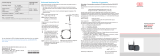
4.5.2 Power Supply
Power supply U
V
: +9 ... 30 VDC (temporarily up to 36 VDC)
Current consumption: I max < 50 mA
The controller is protected against voltage reversal and overvoltage.
i
Only use the power supply for measuring devices and not simultaneously for drives or similar pulse
interference. MICRO-EPSILON recommends the power supply unit PS2020, see Chap. A 1. 12 V on-
board power supply is possible.
PS2020
230 VAC
PE
N L
PS2020
PC140-x
turboSPEED
Remote
SUPP Y /
OUTPUT
Mode
RAW S GNAL
Blades
1
2
3
4
5
6
7
8
9
10
11
12
3
4
15
16
0
0 V
100 110
125
9 V
15 V
24 V
30 V
U /V
V
T/°C
Fig. 13 Connection Power Supply Fig. 14 Derating curve
Wire color PC140-x Assignment The power supply U
V
has to be limited at 100 °C am-
bient temperature and it must not exceed 15 VDC at
125 °C, see Fig. 14.
SUPPLY + brown +9 … 30 VDC
SUPPLY - white Supply -

Page 19
Mounting
turboSPEED DZ140
S
R
Wire
I
Last
U
R Wire
upply +
Supply -
GND
BNC
DZ140 Controller
PE
L
GND
R
Wire
M
V
U
R Leitung
e.g. U
a
, U
Temp
from DZ140
Further
measuring
instruments
Fig. 15 Thermal overheating possible by measuring loop - avoid
If the GND line is connected to the negative pole of the power supply (e.g. due to connected measuring
instruments), avoid connecting the controller to loads with high currents, e.g. starter.
S
R
Wire
I
Last
U
R Wire
upply +
Supply -
GND
BNC
DZ140 Controller
PE
L
GND
R
Wire
M
V
e.g. U
a
, U
Temp
from DZ140
Further
measuring
instruments
Fig. 16 Short connection leads directly to the supply - recommendation
i
Also consider the possible ground loops, which can result from the use of the multi corrugated spring
(connection between GND and PE), see Chap. 6.

Page 20
Mounting
turboSPEED DZ140
4.5.3 RAW SIGNAL
Via a BNC socket RAW SIGNAL the controller provides an analog voltage of 2.8 ... 5 V to align the sensor,
see Fig. 20, see Chap. 5.3.2. Load resistance > 5 kOhm.
Disconnect the connected measuring devices after alignment of the sensor distance and close the
female connector with the delivered protection cap.
4.5.4 Ground Concept
Supply +
Supply -
GND
Shield
BNC
Triax
DZ140 Controller
PEPE PE
L
GND
Sensor
Fig. 17 Ground concept for DSx sensors
/