ALED 260W 360W INSTALLATION INSTRUCTIONS
Thank you for buying RAB lighting xtures. Our goal is to design the best quality products to get the job done right. We’d like to hear your comments.
Call the Marketing Department at 888-RAB-1000 or email: marketing@rabweb.com
®
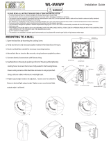
010V DIMMABLE WIRING
Universal voltage driver permits operation at 120V thru 277V,
50 or 60 Hz. 0-10V control wires must be rated for 300V
minimum. Units ordered with (/480) sux are 480V, 50 or
60Hz. For 0-10V Dimming, follow the wiring directions as
shown in gure below.
1. Connect the black xture lead to the LINE supply lead.
2. Connect the white xture lead to the COMMON supply
lead.
3. Connect the GROUND wire from xture to supply ground.
Do NOT connect the GROUND of the dimming xture to
the output.
4. Connect the purple xture lead to the (V+) DIM lead.
5. Connect the gray xture lead to the (V-) DIM lead.
6. Cap the yellow xture lead, if present. Do NOT connect.
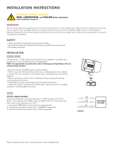
PHOTOCELL INSTALLATION
Photocell may be installed in the eld. Apply weatherproof
silicone sealant to all plugs and unused conduit entries.
1. Knockout hole on top of arm.
2. Install photocell and wire as per diagram.
3. Use photocell rated for your supply voltage.
“COM”
PHOTOCELL
WP2FC
LIGHT
FIXTURE
BLACK
WHITE
PHOTOCELL
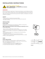
Plugs (2)
Screws (2)
Round Pole Adaptor (RPA) - Ordered separately
RPA
Gasket
Arm Cover
Round Pole
(not supplied)
Arm Gasket
Bolster Plate
Long 3/8” Bolts
ROUND POLE ADAPTOR ACCESSORY
For use with standard RAB pole drilling.
1. Drill round pole using the dimensions shown in the Pole
Drilling Detail.
2. Place Round Pole Adaptor/ RPA (Ordered separately)
and RPA Gasket between the xture and drilled Pole as
shown.
3. Line up top holes of the Gaskets and Round Pole
Adaptor with top hole in the pole drilling pattern.
4. Place long 3/8” Bolts from the ALED through the top
hole of the RPA and Gaskets to the Round Pole thread
into Bolster Plate.
5. Feed wires from Fixture through Gasket into Arm. Feed
supply wires from Pole through Gasket into Arm. Make
necessary connections inside the Arm and knot wires for
strain relief.
6. Replace the Arm Cover, tighten Screws and add the
Plugs. Secure Pole cap.