Page is loading ...

QS4 Fire Alarm Control Panel
Technical Reference Manual
P/N 3100186 • Rev 2.0 • 12JUL01
Technical Manuals Online! - http://www.tech-man.com

Copyright © 2001. All rights reserved.
Compliance Statement
The QS4, hereinafter referred to as the FACP or control panel, when
properly installed, operates as a Local Protected Premises Fire Alarm
System in accordance with the following standards:
• NFPA Standard 72, 1999 Edition
• Underwriters Laboratories Standard 864, 7th Edition
• Underwriters Laboratories of Canada Standard ULC S527
In addition, Auxiliary Fire Alarm System operation requires a Reverse
Polarity Module (RPM). Central Station Fire Alarm System operation
requires a Dialer card (DLD).
Installation in accordance with this manual, applicable codes, and the
instructions of the authority having jurisdiction is mandatory.
Limitation of Liability
Edwards Systems Technology (EST) shall not under any circumstances
be liable for any incidental or consequential damages arising from loss
of property or other damages or losses owing to the failure of EST
products beyond the cost of repair or replacement of any defective
products. EST reserves the right to make product improvements and
changes to product specifications at any time.
While every precaution was taken during the preparation of this
document to ensure its accuracy, EST assumes no responsibility for
errors or omissions.
Fire Alarm System
Limitations
Automatic fire alarm systems can not guarantee against property
damage, loss of property, or loss of life. An automatic fire alarm system's
ability to provide early warning of a developing fire may be limited for a
variety of reasons, but mainly due to improper installation or
maintenance.
The best way to minimize system failures is to perform regularly
scheduled preventive maintenance in accordance with national and local
fire codes. All system components and wiring should be tested and
maintained by trained fire alarm system professionals.
FCC Compliance Statement
This equipment can generate and radiate radio frequency energy. If this
equipment is not installed in accordance with this manual, it may cause
interference to radio communications. This equipment has been tested
and found to comply within the limits for Class A computing devices
pursuant to Subpart B of Part 15 of the FCC Rules. These rules are
designed to provide reasonable protection against such interference
when this equipment is operated in a commercial environment.
Operation of this equipment is likely to cause interference, in which case
the user at his own expense, will be required to take whatever measures
may be required to correct the interference.
Technical Manuals Online! - http://www.tech-man.com

QS4 Technical Reference Manual i
Content
About this manual • iii
Related documentation • iv
Document history • vi
Chapter 1 Product description • 1.1
System overview • 1.2
Component descriptions • 1.3
Circuit descriptions • 1.5
Controls and indicators • 1.9
Controls and indicators behind the flip-down cover • 1.10
Controls and indicators on the zone annunciator card • 1.11
Interpretation of screen displays • 1.12
Chapter 2 Installation • 2.1
Installation do's and don'ts • 2.2
Installation checklist • 2.3
Two ways to install the cabinet: Surface or semi-flush mount • 2.4
How to assemble the panel • 2.6
Wiring mains ac and earth ground • 2.7
System jumper settings • 2.8
System addressing • 2.10
Terminal definitions • 2.14
Connecting a PT–1S printer • 2.22
Installing standby batteries • 2.23
Chapter 3 Operating instructions • 3.1
Instructions for the Level 1 operator (public mode access) • 3.2
Instructions for the Level 2 operator (emergency mode access) • 3.5
Instructions for the Level 3 operator (maintenance mode access) • 3.7
Instructions for the Level 4 operator (service mode access) • 3.10
QuickReference list • 3.11
Chapter 4 Programming instructions • 4.1
Overview • 4.2
QuickStart setup instructions • 4.4
Customizing the system configuration • 4.13
Setting up an Output Group • 4.21
Setting up a Zone • 4.26
Chapter 5 Standard applications • 5.1
Notification appliance circuits • 5.2
Initiating device circuits • 5.5
Coded alarm signaling • 5.8
Remote station protective signaling system • 5.10
Auxiliary protective signaling • 5.12
Chapter 6 Maintenance instructions • 6.1
Pseudo point definitions • 6.2
Maintenance tasks • 6.6
Technical Manuals Online! - http://www.tech-man.com

Content
ii QS4 Technical Reference Manual
Appendix A System calculations • A.1
Notification appliance circuit maximum wire length calculation • A.2
Signature loop maximum wire length calculations • A.3
Battery calculation worksheet • A.8
Appendix B Barcode library • B.1
Appendix C SIGA-REL programming • C.1
Application block diagram • C.2
Programming instructions • C.3
Technical Manuals Online! - http://www.tech-man.com

Content
QS4 Technical Reference Manual iii
About this manual
Organization
This manual provides information on how to properly install, wire, and
maintain the FACP and related components, and is organized as
follows:
Chapter 1 provides a detailed description of the fire alarm control panel
and its operation.
Chapter 2 provides instructions for installing the fire alarm control
panel.
Chapter 3 provides instructions for operating the control panel.
Chapter 4 provides instructions for programming the fire alarm system
from the front panel.
Chapter 5 provides simplified wiring schematics for standard
applications.
Chapter 6 provides instructions for maintaining the system.
Appendix A provides worksheets for calculating maximum wire lengths
for notification and Signature circuits, and for sizing standby batteries.
Appendix B provides a set of bar codes that you can use to enter text
for location messages.
Appendix C provides information on how to program the SIGA–REL
using the QS–CU (QuickStart Configuration Utility).
Safety information
Important safety admonishments are used throughout this manual to
warn of possible hazards to persons or equipment.
WARNING: Warnings are used to indicate the presence of a hazard
which will or may cause personal injury or death, or loss of service if
safety instructions are not followed or if the hazard is not avoided.
Caution: Cautions are used to indicate the presence of a hazard which
will or may cause damage to the equipment if safety instructions are not
followed or if the hazard is not avoided.
Technical Manuals Online! - http://www.tech-man.com

Content
iv QS4 Technical Reference Manual
Related documentation
National Fire Protection Association
1 Batterymarch Park
P.O. Box 9101
Quincy, MA 02269-9101
NFPA 70 National Electric Code
NFPA 72 National Fire Alarm Code
NFPA 11 Low-Expansion Foam Systems
NFPA 11A Medium- and High-Expansion Foam Systems
NFPA 12 Carbon Dioxide Extinguishing Systems
NFPA 13 Sprinkler Systems
NFPA 15 Water Spray Fixed Systems for Fire Protection
NFPA 16 Deluge Foam-Water Sprinkler and Foam-Water Spray
Systems
NFPA 17Dry Chemical Extinguishing Systems
Underwriters Laboratories, Inc.
333 Pfingsten Road
Northbrook, IL 60062-2096
UL 38 Manually Actuated Signaling Boxes
UL 217 Smoke Detectors, Single & Multiple Station
UL 228 Door Closers/Holders for Fire Protective Signaling
Systems
UL 268 Smoke Detectors for Fire Protective Signaling Systems
UL 268A Smoke Detectors for Duct Applications
UL 346 Waterflow Indicators for Fire Protective Signaling
Systems
UL 464 Audible Signaling Appliances
UL 521 Heat Detectors for Fire Protective Signaling Systems
UL 864 Standard for Control Units for Fire Protective Signaling
Systems
UL 1481 Power Supplies for Fire Protective Signaling Systems
UL 1638 Visual Signaling Appliances
UL 1971 Visual Signaling Appliances
Underwriters Laboratories of
Canada
7 Crouse Road
Scarborough, ON
Canada M1R 3A9
Canadian Electrical Code Part 1
ULC S527 Standard for Control Units for Fire Alarm Systems
ULC S524 Standard for the Installation of Fire Alarm Systems
ULC S536 Standard for the Inspection and Testing of Fire
Alarm Systems
ULC S537 Standard for the Verification of Fire Alarm Systems
ULC ORD–C693–1994 Central Station Fire Protective Signaling
System and Services
Technical Manuals Online! - http://www.tech-man.com

Content
QS4 Technical Reference Manual v
Edwards Systems Technology
6411 Parkland Drive
Sarasota, FL 34243
2–CTM City Tie Module Installation Sheet (P/N 270496)
CDR–3 Bell Coder Installation Sheet (P/N 3100023)
DLD Dual Inline Dialer Installation Sheet (P/N 3100187)
PS6 Power Supply Card Installation Sheet (P/N 3100201)
QSA–1(X), QSA–2(X) Remote Annunciator Cabinet Installation
Sheet (P/N 3100295)
QS–CPU(X) CPU/Display Unit Installation Sheet (P/N 3100276)
SL30, SL30–1 LED/Switch Card Installation Sheet (P/N
3100193)
SLIC Signature Intelligent Controller Card Installation Sheet
(P/N 3100192)
RS485 (NT–A) Card and QS–232 UART Module Installation
Sheet (P/N 3100191)
ZA8–2 Class A Zone Card Installation Sheet (P/N 3100189)
ZB16–4 Class B Zone Card Installation Sheet (P/N 3100188)
ZR8 Relay Card Installation Sheet (P/N 3100190)
SIGA–APS Auxiliary Power Supply Installation Sheet (P/N
387342)
Signature Series Intelligent Smoke and Heat Detectors
Applications Bulletin (P/N 270145)
Signature Series Component Installation Manual (P/N 270497)
EST Strobe Applications Guide (P/N 85000-0049)
QuickStart Online Help Utility (P/N 7350047)
QuickStart ULI and ULC Compatibility Lists (P/N 3100335)
Network Hardware Technical Reference (P/N 250100)
Technical Manuals Online! - http://www.tech-man.com

Content
vi QS4 Technical Reference Manual
Document history
Date Revision Description of changes
24JUN01 1.0 Original release.
12JUL01 2.0 Corrections and additions on pp 2.12, 2.24, 3.9, 4.4, 4.8, 4.10, 4.19,
A.3.
Technical Manuals Online! - http://www.tech-man.com

QS4 Technical Reference Manual 1.1
Chapter 1
Product description
Summary
This chapter provides a detailed description of the fire alarm control
panel and its operation.
Content
System overview • 1.2
Component descriptions • 1.3
Circuit descriptions • 1.5
Controls and indicators • 1.9
Controls and indicators behind the flip-down cover • 1.10
Controls and indicators on the zone annunciator card • 1.11
Interpretation of screen displays • 1.12
Technical Manuals Online! - http://www.tech-man.com

Product description
1.2 QS4 Technical Reference Manual
System overview
System hardware capabilities
Hardware capabilities vary depending on cabinet
size and option card configuration, but generally:
• Up to four Class A or Class B Signature
signaling line circuits that support up to 250
single-address Signature devices each
• Up to 40 Class A or 48 Class B initiating device
circuits (IDC). Combination systems can not
exceed 40 IDC circuits total
• Up to 16 Class A or 20 Class B notification
appliance
• Up to two 30-zone displays
• Up to 96 dry-contact relay
• 4.5 amps of 24 Vdc power for external
notification appliances
• Battery charger capable of charging batteries
rated up to 40 Ah. Maximum battery size for
ULC applications is 30 Ah
• Up to eight, fully-supervised, mirrored or
customized remote annunciators
Minimum system requirements
A Local Protected Premises Fire Alarm System
requires only the FACP (CPU, PS6, and
enclosure) with at least one SLIC, ZB16–4, or
ZA8–2 card programmed with at least one audible
output circuit and one alarm input circuit.
In addition to the hardware requirements of a
Local system:
• Add a 2–CTM City Tie Module for an Auxiliary
Fire Alarm System
• Add a DLD Dual Line Dialer Card or RPM
Reverse Polarity Module for a Remote
Supervising Station Fire Alarm System
• Add a DLD Dual Line Dialer Card or RPM
Reverse Polarity Module for a Central Station
Fire Alarm System
• Add a SIGA–REL for Releasing Device Service
Normal operating mode description
The panel operates in normal mode in the
absence of any alarm, supervisory, trouble, and
monitor events. In normal mode, the control panel
monitors the system for any events.
Off-normal operating mode description
The panel operates in off-normal mode any time
there is an event introduced into the system.
When this happens, the CPU:
• Changes the contact positions on the
appropriate common relays
• Activates all common alarm outputs (alarm
events only)
• Turns on the panel buzzer
• Executes the appropriate programmed output
response for the input that signaled the event
• Sends a record of the event to the appropriate
display queue and out the serial port
If there is no operator in attendance, the panel
displays the content of the highest priority display
queue containing a record.
If there is an operator in attendance, the panel
displays the content of the current display queue
regardless of any new events introduced into the
system.
Failsafe operating mode description
The panel operates in failsafe mode when the
CPU loses the ability to communicate with the PS6
and JP1 on the PS6 is in the ON position. When
this happens, the power supply:
• Closes the common trouble relay contacts
• Instructs the dialer to send the default trouble
message
• Monitors the system for any alarm events
If an alarm event occurs, the power supply:
• Changes the contact positions on the common
alarm relay
• Turns on all conventional common alarm
outputs. Signature common alarm outputs are
not affected.
• Instructs the dialer to send the default alarm
message
Technical Manuals Online! - http://www.tech-man.com

Product description
QS4 Technical Reference Manual 1.3
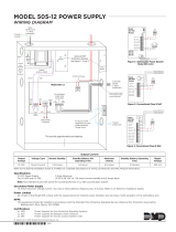
Component descriptions
1 2 3
6A
5
6B
7 84
9
10
J5
13
JP1
J2
J7
J8
JP1 CONFIGURATION
PIN 1 & 2 = MODEM PWR
PIN 2 & 3 = RTS
J6
14 13 111215
1. Cabinet enclosure: Houses the panel
electronics and standby batteries.
2. SL30–1 LED/Switch Card: Provides thirty
circuits for point or zone annunciation. Each
circuit has two LEDs for annunciating alarm,
supervisory, and trouble signals, and a button
numbered from 31 to 60.
3. SL30 LED/Switch Card: Same as SL30–1
except the buttons are numbered 1–30.
4. CPU/Display: Provides operator access to
system messages, status information, and
programming menus, and executes system
responses based on the panel programming.
5. PS6 Power Supply Card: Provides primary dc
power to the panel electronics and external
circuits. The PS6 also provides common alarm,
supervisory and trouble relays for remote station
supervision.
Technical Manuals Online! - http://www.tech-man.com

Product description
1.4 QS4 Technical Reference Manual
6. RS485 (NT–A) Class A Card: The NT–A
comprises the RS485 card and QS–232 UART
module. Together these provide an additional
RS–232 channel to allow Class A communication
between the control panel and other remote
annunciator panels. Control panels require
installation of both cards while remote
annunciator panels only require installation of a
QS–232 card and only then if you want to
connect a printer or service computer.
7. ZA8–2 Class A Conventional Zone Card:
Provides six dedicated Class A initiating device
circuits (IDCs) for connecting two-wire smoke
detectors and dry-contact initiating devices. The
ZA8–2 also provides two circuits that you can
configure as IDCs or as 24 Vdc notification
appliance circuits (NACs).
8. ZB16–4 Class B Conventional Zone Card:
Provides twelve dedicated Class B initiating
device circuits (IDCs) for connecting two-wire
smoke detectors and dry-contact initiating
devices. The ZB16–4 also provides four circuits
that you can configure as IDCs or as Class B 24
Vdc notification appliance circuits (NACs).
9. QS–Cable12 Expansion Cable: Extends the
CPU data and power bus to circuit cards installed
on the lower DIN rail in the 12-option cabinet.
10. ZR8 Relay Card: Provides eight dry-contact
relays. You can configure each relay for
normally-open or normally-closed operation.
11. DLD Dual Line Dialer Card: Provides two
telephone line connections for sending system
messages to a compatible Digital Alarm
Communicator Receiver.
12. SLIC Signature Loop Intelligent Controller
Card: Provides one Class A or Class B signaling
line circuit (loop) for connecting Signature series
detectors and modules. The SLIC also provides
two Class A or Class B notification appliance
circuits (NACs) for connecting polarized 24 Vdc
notification appliances (horns, strobes).
13. Standby batteries: Provides dc power to the
panel electronics in the absence of ac power.
14. Transformer: Changes the mains ac supply
voltage for the power supply card.
15. AC wiring block and fuse holder: Provides
connections for mains ac (primary power) and 5A
fuse.
Technical Manuals Online! - http://www.tech-man.com

Product description
QS4 Technical Reference Manual 1.5
Circuit descriptions
PS6 Power Supply Card
1. Relay 1 (Common Alarm)
Style: Form C
Contact rating: 1 A @ 20.4 – 26.4 Vdc (0.6 PF)
Wire size: 18 to 12 AWG (0.75 to 2.5 mm²)
Nonsupervised and power-limited only when
connected to a power-limited source
2. Relay 2 (Common Supervisory)
Style: Normally-open
Contact rating: 1 A @ 20.4 – 26.4 Vdc (0.6 PF)
Wire size: 18 to 12 AWG (0.75 to 2.5 mm²)
Nonsupervised and power-limited only when
connected to a power-limited source
3. Relay 3 (Common Trouble)
Style: Normally-open, held closed
Contact rating: 1 A @ 20.4 – 26.4 Vdc (0.6 PF)
Wire size: 18 to 12 AWG (0.75 to 2.5 mm²)
Nonsupervised and power-limited only when
connected to a power-limited source
4. Relay 4 (Programmable)
Style: Normally-open
Contact rating: 1 A @ 20.4 – 26.4 Vdc (0.6 PF)
Wire size: 18 to 12 AWG (0.75 to 2.5 mm²)
Nonsupervised and power-limited only when
connected to a power-limited source
5. Smoke/Accessory Power
Output: Continuous or interruptible via jumper
selection
Voltage: 24 Vdc, regulated
Current: 250 mA
Wire size: 18 to 12 AWG (0.75 to 2.5 mm²)
Supervised and power-limited
71
2
6
9
8
534
6. RS485
Wire size: 18 to 12 AWG (0.75 to 2.5 mm²)
Wire type: Twisted pair, six twists per foot
minimum
Circuit capacitance: 0.4 µF
Circuit resistance: 100 Ω
Supervised and power-limited
8. AUX Power #1, #2, and #3
Voltage: 17.5 – 26.4 Vdc FWR (full wave
rectified)
Current: 1.5 A each
Wire size: 18 to 12 AWG (0.75 to 2.5 mm²)
Power-limited and supervised for short circuit
conditions only
7. RS232
Wire size: 18 to 12 AWG (0.75 to 2.5 mm²)
Nonsupervised and power-limited
Wire length: 20 ft maximimum
9. Battery Circuit
Charge current: 2 A
Charge capacity: 40 Ah (UL), 30 Ah (ULC)
Supervised and nonpower-limited
Technical Manuals Online! - http://www.tech-man.com

Product description
1.6 QS4 Technical Reference Manual
SLIC Signature Loop Intelligent Controller Card circuits
1. NAC #1
Configuration: Class B or Class A
Output voltage: 24 Vdc, nominal
Output current: 2.0 A @ 24 Vdc
Wire size: 18 to 12 AWG (0.75 to 2.5 mm
2
)
End of line resistor: 10 kΩ, 1/2W
Supervised and power-limited
2. NAC #2
Configuration: Class B or Class A
Output voltage: 24 Vdc, nominal
Output current: 1.0 A @ 24 Vdc
Wire size: 18 to 12 AWG (0.75 to 2.5 mm
2
)
End of line resistor: 10 kΩ, 1/2W
Supervised and power-limited
3. Signature Loop
Configuration: Class B (Style 4) or Class A (Style 6)
Capacity: 125 Signature detectors, 125 Signature single-address
modules
Wire size: 18 to 12 AWG (0.75 to 2.5 mm
2
)
Circuit resistance: 65 Ω
Circuit capacitance: 0.3 µF
Supervised and power-limited
4. NAC Riser In/Out
Voltage: 24 Vdc, nominal
Wire size: 18 to 12 AWG (0.75 to 2.5 mm
2
)
12
43
ZR8 Relay Card circuits
1. Dry-contact relays R1 – R4
Outputs: Normally-open or normally-closed contacts via jumper
selection
Contact rating: 24 Vdc @ 1.0 A
Wire size: 18 to 12 AWG (0.75 to 2.5 mm
2
)
Nonsupervised, and power-limited only when connected to a
power-limited source
2. Dry-contact relays R5 – R8
Outputs: Normally-open or normally-closed contacts via jumper
selection
Contact rating: 24 Vdc @ 1.0 A
Wire size: 18 to 12 AWG (0.75 to 2.5 mm
2
)
Nonsupervised, and power-limited only when connected to a
power-limited source
1
2
Technical Manuals Online! - http://www.tech-man.com

Product description
QS4 Technical Reference Manual 1.7
ZB16–4 Class B Conventional Zone Card circuits
1. IDC Circuits Z1 – Z12
Wiring configuration: Class B
Detector voltage: 20.33 – 24.76 Vdc, max ripple 2000 mV
Short circuit current: 75.9 mA, max.
Resistance: 50 Ω, max.
Capacitance: 100 µF, max
Wire size: 18 to 12 AWG (0.75 to 2.5 mm
2
)
End of line resistor: 4.7 kΩ, 1/2W
Supervised and power-limited
2. NAC Circuits Z13 – Z16
Wiring configuration: Class B
Output voltage: 24 Vdc, nominal
Output current: 2.0 A @ 24 Vdc
Wire size: 18 to 12 AWG (0.75 to 2.5 mm
2
)
End of line resistor: 10 kΩ, 1/2W
Supervised and power-limited
IDC specifications apply when programmed as IDC circuit
3. R1
Voltage: 24 Vdc, nominal
Wire size: 18 to 12 AWG (0.75 to 2.5 mm
2
)
4. R2
Voltage: 24 Vdc, nominal
Wire size: 18 to 12 AWG (0.75 to 2.5 mm
2
)
1
3
4
2
1
ZA8–2 Class A Conventional Zone Card circuits
1. IDC Circuits Zone 1 – Zone 3, Zone 5 – Zone 7
Wiring configuration: Class A
Detector voltage: 19.90 – 22.46 Vdc, max ripple 2000 mV
Short circuit current: 75.9 mA, max.
Resistance: 50 Ω, max.
Capacitance: 100 µF, max
Wire size: 18 to 12 AWG (0.75 to 2.5 mm
2
)
End of line resistor: 4.7 kΩ, 1/2W
Supervised and power-limited
2. NAC Circuits Zone 4, Zone 8
Wiring configuration: Class A
Output voltage: 24 Vdc, nominal
Output current: 2.0 A, 24 Vdc
Wire size: 18 to 12 AWG (0.75 to 2.5 mm
2
)
End of line resistor: 10 kΩ, 1/2W
Supervised and power-limited
IDC specifications apply when programmed as IDC circuit
3. NAC PWR IN (Zone 4)
Voltage: 24 Vdc, nominal
Wire size: 18 to 12 AWG (0.75 to 2.5 mm
2
)
4. NAC PWR IN (Zone 8)
Voltage: 24 Vdc, nominal
Wire size: 18 to 12 AWG (0.75 to 2.5 mm
2
)
1
2
3
1
4
2
Technical Manuals Online! - http://www.tech-man.com

Product description
1.8 QS4 Technical Reference Manual
DLD Dual Line Dialer Card circuits
1. Line #1
Supervised and nonpower-limited
2. Line #2
Supervised and nonpower-limited
12
RS485 (NT–A) Class A Card circuits
1. Secondary RS485 channel
Wire size: 18 to 12 AWG (0.75 to 2.5 mm
2
)
Supervised and power-limited
2. Primary RS485 channel
Wire size: 18 to 12 AWG (0.75 to 2.5 mm
2
)
Supervised and power-limited
Note: JP1 installed for ground fault detection on RS485 circuits.
12
Technical Manuals Online! - http://www.tech-man.com

Product description
QS4 Technical Reference Manual 1.9
Controls and indicators
1234
1
67890
2
3
5
4
5
6
7
8
9
10
11
12
13
14
15
16
17
18
19
20
21
22
23
24
25
26
27
28
29
30
12
2
345 61 78
9
1
2
3
4
5
6
7
8
9
10
11
12
13
14
15
16
17
18
19
20
21
22
23
24
25
26
27
28
29
30
11 10
1. Text display and controls: Displays system
messages, status information, programming
menus.
Moves the cursor up one line at a time or
to the previous record in the display
queue
Moves the cursor down one line at a time
or to the next record in the display queue
Moves the cursor right one character at a
time or to the next display queue
Moves the cursor left one character at a
time or to the previous display queue
Enters operator input and selects menu
items
2. Alarm LED: Indicates the panel posted an
alarm event record into the corresponding display
queue.
3. Supervisory LED: Indicates the panel posted
a supervisory event record into the corresponding
display queue.
4. Disable/Test LED: Indicates part of the
system is disabled or is currently under test.
Disabled components also signal a system
trouble.
5. Monitor LED: Indicates the panel posted a
monitor event record into the corresponding
display queue.
6. Trouble LED: Indicates the panel posted a
trouble event record into the corresponding
display queue.
7. Ground Fault LED: Indicates a ground fault in
the system wiring. Ground faults also signal a
system trouble.
8. CPU Fail LED: Indicates an unexpected
reboot or failure with the microprocessor. CPU
failures also signal a system trouble.
9. Power LED: Indicates the panel has ac power.
10. Panel Silence/Acknowledge button/LED:
Turns off the panel buzzer and acknowledges all
events. The Panel Silenced LED indicates that all
off normal events have been acknowledged and
the internal buzzer is off.
11. Status button: Displays the Status menu
from which you can identify active or disabled
points in the system.
12. Help button: Provides additional information
for the event record selected on the display.
Technical Manuals Online! - http://www.tech-man.com

Product description
1.10 QS4 Technical Reference Manual
Controls and indicators behind the flip-down cover
1234
1
67890
2
3
5
4
5
6
7
8
9
10
11
12
13
14
15
16
17
18
19
20
21
22
23
24
25
26
27
28
29
30
1
2
3
4
5
6
7
8
9
10
11
12
13
14
15
16
17
18
19
20
21
22
23
24
25
26
27
28
29
30
3
6
9
5
8
4
7
2
1
1. Enable Controls key switch: Gives priority
access to control functions reserved for operators
with Level 2 access.
2. Barcode scanner jack: Input point for optional
barcode scanner.
3. Numeric keypad: Numbered buttons for
entering data and selecting menu options.
4. Reset button: Restores devices or zones in
alarm or trouble to their standby condition. The
LED indicates when the panel is resetting.
5. Alarm Silence button: Turns active
notification appliances off according to the panel
programming. Pressing Alarm Silence a second
time turns them back on. The LED indicates
when the panel is in alarm and operating with
notification appliances turned off.
6. Drill button: Turns notification appliances on
according to the panel programming but does not
place the panel in alarm. The LED indicates
when the panel is in Drill mode.
7. Menu button: Displays the operator menus.
8. Delete button: Returns to the previous menu
or back spaces the cursor.
9. Enter button: Press the Enter button to accept
information from the operator or continue to the
next item.
Technical Manuals Online! - http://www.tech-man.com

Product description
QS4 Technical Reference Manual 1.11
Controls and indicators on the zone annunciator card
1
2
3
4
5
6
7
8
9
10
11
12
13
14
15
16
17
18
19
20
21
22
23
24
25
26
27
28
29
30
21 3
1. Zone display button: Displays an event
record for each device in the corresponding zone
that signaled an alarm.
2. Zone active LED: Indicates a device in the
corresponding zone signaled an alarm condition.
3. Zone trouble LED: Indicates a device or
wiring fault in the corresponding Zone.
Note: ULC requires that every fire panel have the
capability to visually display system status by
means of specific indicators for each zone. All
status changes must clearly indicate that the
information is an Alarm (ALM), Supervisory
(SUP), Trouble (TBL), or Monitor (MON).
Technical Manuals Online! - http://www.tech-man.com

Product description
1.12 QS4 Technical Reference Manual
Interpretation of screen displays
HH:MM:SS MM/DD
System
Normal
Project Name
Alarm History:
nnnn
This is what the panel display looks like when there are no event
records posted in a display queue.
HH:MM:SS is the current time in hours, minutes, and seconds
MM/DD is the current month and date
nnnn is the number times the panel went into alarm since being
placed into service
HH:MM:SS
Axxx Dxxx
nnn event name
Custom message 1
Custom message 2
nnn event name
Custom message 1
Custom message 2
ALM SUP TRBL MON
aaa sss ttt mmm
This is what the panel display looks like when there are event
records posted in a display queue.
HH:MM:SS is the current time in hours, minutes, and seconds
Axxx is the current number of active points
Dxxx is the current number of disabled points
These items comprise the event record:
nnn is the posting sequence number (001 = first, 002 = second, and
so on)
event name is the event produced when the device changed states.
Refer to Table 1-1.
P:pp C:cc D:ddd is the address of the device that signaled the
event (P = panel number, C = card number, D = device number)
The event record may also include a custom message that typically
indicates the location of the device, depending on the panel
programming.
These items indicate the content of the display queues:
aaa is the number of alarm event records (highest priority)
sss is the number of supervisory event records
ttt is the number of trouble event records
mmm is the number of monitor event records (lowest priority)
Technical Manuals Online! - http://www.tech-man.com
/