Page is loading ...

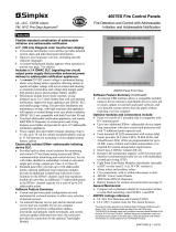
Features
Standard features:
• 80 Character, alphanumeric LCD readout with wide
viewing angle
• Eight, Class B Initiating Device Circuits (IDCs)
• Four, Class B Notification Appliance Circuits (NACs)
• 4 A power supply/battery charger
• Power-limited design
• Pluggable terminal blocks
• Internal DACT is included on UL listed models;
available separately as required for ULC listed models
Simplex
®
system accessory compatibility:
• 4602 Series Remote Control Unit (RCU) and Status
Command Unit (SCU), two-wire serial
communications
• 4601 Series Annunciators
• 4003 Voice Control Panels
• 4009 NAC Power Extenders
Software features:
• Menu-driven programming
• On-site programmable custom labels
• Four operator access levels
• Historical event logs
• Circuit selectable alarm verification
• WALKTEST™ one-person system testing**
• Selectable active status reminder
Optional expansion:
• Two circuit IDC, two circuit NAC/relay
†
• Four circuit NAC/relay
†
• Four circuit IDC (low current and high current
versions)
• Four circuit Class A NAC or IDC zone conversion
• Eight circuit I/O module
• Remote station/city connection
• Additional 5 A power supply
UL Listed to Standard 864
* Refer to page 6 for additional ULC listing information. This product has been approved by
the California State Fire Marshal (CSFM) pursuant to Section 13144.1 of the California
Health and Safety Code. See CSFM Listing 7165-0026:212 for allowable values and/or
conditions concerning material presented in this document. It is subject to
re-examination, revision, and possible cancellation. Accepted for use – City of New York
Department of Buildings – MEA35-93E. See page 7 for ULC designations. Additional
listings may be applicable; contact your local Simplex product supplier for the latest
status. Listings and approvals under Simplex Time Recorder Co. are the property of Tyco
Safety Products Westminster.
CAUTION
DISCONNECT
BATTERY AND
A. C. POWER
BEFORE
SERVICING
ALARM
ACK
SUPV
ACK
TROUBLE
ACK
ALARM
SILENCE
SYSTEM
RESET
FIRE
ALARM
SYSTEM
SUPERVISO RY
SYSTEM
TROUBLE
ALARM
SILENCED
AC
POWER
Model 4005 Fire Alarm Control Panel
Introduction
For areas requiring eight to thirty-six IDC zones, Simplex
4005 series fire alarm control panels provide flexible
initiating circuit monitoring, extensive programmable
control capability, and LCD annunciated circuit-specific
custom labels. Surface mount components, efficient
microprocessor programming, and easy-to-use control
panel operation combine to provide an extensive feature
list in a compact, “installation friendly” package.
Panel status and circuit information is efficiently
indicated by an alphanumeric LCD readout featuring two
lines of 40 characters each. The panel control switches are
clearly marked for intuitive operation. Programming of
the selectable features is performed by using the display
and the panel control switches while in the programming
mode.
Applications
The 4005 series fire alarm control panel provides
protection for a wide variety of mid-size facilities in the
following fields: Educational, Health Care, Business,
Storage, Hospitality, Residential, and General Assembly.
Its modular design allows IDCs and NACs to be
incremented in groups of two or four to satisfy circuit
requirements without specifying excess capacity. If the
system expands, then additional “snap-in-place” modules
can be easily installed on-site.
** WALKTEST performance testing is protected under US Patent No. 4,725,818.
† NACs may be individually configured for dry contact relay operation.
NOTE: Contact your local Simplex product supplier for fire alarm control panels suitable for
Release Control applications.
LifeAlarm
®
Fire Alarm Control Panels
UL, ULC, CSFM Listed; FM Approved; 4005 Series Fire Alarm Control Panels
MEA (NYC) Acceptance* Providing 8 to 36 IDCs and 4 NACs
S4005-0001-9 3/2009

4005 Module Features
The CPU board contains the main microprocessor and
panel programming, evaluates the status of all I/O
modules, processes the required responses, and provides a
watchdog timer that resets the panel in the event of an
abnormal operation. Additional details are below.
• Controls the LCD readout and switches that comprise
the operator interface
• Controls the flash EPROM that contains the non-volatile
site-specific programming information
•
4-Wire Smoke Detector Power provides a 5 second
reset; rated 500 mA @ 24 VDC, open collector output,
and is power-limited and short circuit protected
•
Remote Unit Serial Interface (RUI) output provides
connections for up to 16, Class B supervised remote
annunciators, Remote Control Unit (RCU) model
4602-9102,or Status Command Unit (SCU) model
4602-9101; (see additional description under
Accessories on page 5)
Power Distribution Board Features:
• Provides connections for up to 5 plug-in module cards
•
Auxiliary power connections. Two power-limited
connections are provided, each rated for 2 A @ 24 VDC;
connections are isolated from NAC power
Power Supply/Battery Charger features:
• Switch Selectable for 120 or 240 VAC
•
24 VDC Power, regulated and power-limited, is
available specifically for notification appliances and
auxiliary output use via two taps of 2 A each; rated 4 A
for Special Application Appliances and 2 A for
Regulated 24 DC power
•
Internal System Operating Power is supplied via
separate power-limited connections.
•
Battery Charging for up to 18 Ah batteries mounted
within the 4005 cabinet and up to 33 Ah batteries when
mounted in an external battery cabinet.
•
Function Monitoring. Includes: missing, depleted, and
low battery, Earth fault detection, AC power loss, AC
power brownout (low input voltage), signal power
overload, supply voltage monitoring, and charger failure.
•
Depleted Battery Trouble Indication advises when
standby operation has exceeded battery capacity.
Internal DACT Module features:
• Reports Alarm, Supervisory, Trouble, and AC Failure
• Dual line operation with automatic 24 hour test and
programmable power fail report delay
Eight, Initiating Device Circuits (IDCs) features:
• Two, 4 circuit IDC plug-in modules are standard,
providing 8, Class B IDCs
• Standard IDCs are low current and support up to 20
Simplex detectors per IDC at 2 mA maximum (for
detectors with relay bases, use high current expansion
modules, see chart on page 7)
4005 Module Features (Continued)
IDC operation is individually programmable with
the following 28 operating mode choices (the abbreviated
description is part of the IDC display information):
Point Type Description Point Type Description
FIRE
Fire Monitor
Zone
FPUMP
Fire Pump
Monitor
WATER
WaterFlow
Monitor
SFPUMP
Supervised Fire
Pump
HEAT Heat Detector S2STAGE 2 Stage Monitor
DUCT Duct Detector
SO
Sprinkler
Normally Open
FLAME Flame Detector
SC
Sprinkler
Normally Closed
PULL
Manual Pull
Station
WSO
Waterflow/
Sprinkler Open
SMOKE Smoke Detector
WSC
Waterflow/
Sprinkler Closed
EMERG
Monitor-Fire
Emergency
SUPV
Supervisory
Monitor
SFIRE
Monitor-
Smoke/Fire
UTIL Utility Monitor
VFIRE
Monitor-Verified
Smoke/Pull
TROUBLE Trouble Monitor
SPULL
Monitor-
Smoke/Pull
VSMOKE
Verified Smoke
Detector
VSPULL
Verified
Smoke/Pull
GVMON
Generic Verified
Zone
GENMON
Generator
Monitor
LATSUPV
Supervisory
Latching
SGENMON
Supervisory
Generator
STYLEC
Monitor-Style C
Monitor
Notification Appliance Circuits (NACs)
One, 4 circuit NAC/Relay plug-in module is standard,
providing 4, Class B NACs that can be individually
reconfigured for dry contact relay operation.
NAC operation is individually programmable
as
Steady Signaling, Temporal Pattern, March Time @
20 BPM, or March Time @ 120 BPM, and with the
following 17 operating modes (the abbreviated
description is part of the NAC display information):
Point Type Description Point Type Description
SSIGNAL
Fire Signal (On
until Silence)
RWATER
WaterFlow (On
until Reset)
RSIGNAL
Fire Signal (On
until Reset)
SUPV
Sprinkler
Supervisory
Signal
TSIGNAL
Trouble (On
until Clear)
PRIMARY
Elevator Capture
(primary
BSIGNAL
Trouble (On
until ACK)
ALTERN
Elevator Capture
(alternate)
SVISUAL
Visual (On until
Silence)
AHUR AHU Relay
RVISUAL
Visual (On until
Reset)
AHUO AHU On Relay
CODED Coded Signal
AHUF AHU Off Relay
SIGNAL Signal Circuit
DHOLDER Door Holder
SWATER
WaterFlow (On
until Silence)
2 S4005-0001-9 3/2009

NAC Relay Mode Operation
NAC/Relay Selection. Each NAC can be on-site
selected for NAC operation or for unsupervised, dry
contact, auxiliary relay operation. When operating in the
relay mode, either the normally open or the normally
closed contact can be connected to the output terminal
block. Contacts are rated at 2 A @ 32 VDC, for transient
suppressed loads.
Relay Operation is individually programmable with the
following 17 operating mode choices (the abbreviated
description is part of the relay display information).
Relay Modes:
Point Type Description Point Type Description
RELAY Auxiliary Relay
BRELAY
Trouble Relay
(On until Ack)
PRIMARY
Elevator Capture
(Primary)
DHOLDER Door Holder
ALTERN
Elevator Capture
(Alternate)
SVISUAL
Visual (On until
Silence)
AHUR AHU Relay
RVISUAL
Visual (On until
Reset)
AHUO AHU On Relay CODED Coded Relay
AHUF AHU Off Relay
SWATER
Waterflow Relay
(On until
Silence)
SRELAY
Fire Relay (On
until Silence)
RWATER
Waterflow Relay
(On until Reset)
RRELAY
Fire Relay (On
until Ack)
SUPV
Supervisory
Relay
TRELAY
Trouble Relay (On
until Clear)
4005 Basic Operator Functions
Display Indications. Upon receiving an abnormal
condition of alarm, supervisory, or trouble, the 80
character backlit LCD will identify the quantity and type
of abnormal indications. With the locked door closed, the
display, status LEDs and primary operator switches are
visible through the transparent door viewing panel as
shown in Figure 1 below. This figure represents the LCD
during normal conditions showing normal status, time,
and date.
ALARM
ACK
SUPV
ACK
TROUBLE
ACK
ALARM
SILENCE
SYSTEM
RESET
FIRE
ALARM
SYSTEM
SUPERVISORY
SYSTEM
TROUBLE
ALARM
SILENCED
AC
POWER
Figure 1. Basic Operator Function Keys with Normal
Display of Status, Time, and Date
4005 Basic Operator Functions (Continued)
Typical Displays. Figure 2 (below) represents typical
fire alarm display screens. For this example, the presence
of three fire alarm conditions is shown in the top screen –
fire zones 2, 7, and 6, displayed in chronological order of
occurrence (up to 10 zones may be shown). The display
will alternate with the one shown below it as the operator
is prompted to assist with the next required action.
Figure 2. Typical 4005 Displays with Alarm Activity
Alarm, Supervisory, and Trouble ACK
Operator Actions. The ALARM ACK, SUPV ACK, or
TROUBLE ACK key will silence the local tone-alert,
corresponding to the type of abnormal condition.
Subsequent entry of the appropriate ACK key will
chronologically scroll through the specifics for each
abnormal condition. Screen information includes custom
labels for each zone that provides a detailed report of the
location, device type description, device condition, and
list count for the first point in the Alarm, Supervisory, or
Trouble list.
Custom Label Display. Figure 3 represents a typical
screen that would appear after using the ALARM ACK
key to scroll to the first fire condition. It displays the zone
location as “First Floor East Wing Room 12”, the device
type as “Smoke Detector” and the device condition of
“Alarm”. The 1/3 indicates that the displayed alarm is the
first of three alarms present in the panel at this time.
Site-specific labels can be upper or lower case and can
provide discrete annunciation that can assist fire response
with clearly defined zone locations and device types.
Figure 3. Typical 4005 Fire Alarm Information Custom
Label Display
Alarm Silence. The ALARM SILENCE key will
silence the notification appliances programmed for
on-until-silence (typically audible notification appliances)
and the ALARM SILENCED LED will remain
illuminated until the panel is reset.
System Reset. When the source of the abnormal
condition is corrected, the SYSTEM RESET key will
reset the panel and return the status to normal.
3 S4005-0001-9 3/2009

Passcode Access, Four Levels
Level 1 is basic access and is available by unlocking the
door. Access includes the standard operator functions and
historical log information.
Levels 2 and 3 are on-site programmable to control
functions required by local needs such as clock set,
enable/disable, WALKTEST system test, and custom
label changes.
Level 4 access provides passcode programming of
critical life safety functions, access level programming,
and service level diagnostics and programming.
Expanded Operator Functions
Unlocking the door provides access to the operator
control panel and reveals nine additional keys used for
expanded operator functions and for circuit type and
programming selections (refer to Figure 4 above).
The following expanded operator functions are available:
Circuit Disable/Enable, available for each individual
IDC, NAC, or relay circuit.
WALKTEST Performance Testing allows a single
fire alarm system tester to manually initiate remote alarms
and troubles and obtain a verification output from the
NACs with an automatic Reset. Alarms are initiated to
produce a pulse count that identifies the zone. With the
zone number confirmed, troubles can be then initiated
with a common pulse output for a complete functional test
of each zone.
Indicator Test confirms that all panel LED and LCD
indicators are properly functioning.
History Logs provide up to 50 fire alarm logs and up to
100 trouble logs. They are available for chronological
review as fire, trouble, or fire and trouble combined.
Programming Operations
NOTE: During programming, monitoring remains active
and the 4005 will perform enabled responses.
Programmable operations include:
• Abort Enable; 30 second delay allows zone status
confirmation before enabling
• Alarm Cutout time delay
• Active Status Reminder (Alarm/Supervisory/Trouble
Resound every 8 hours)
• Alarm Silence Inhibit Timer
• Assignment and selection of passcodes and access
levels
• Custom control equations
• Custom label generation and revision
• Doorholder time delay (drop upon Alarm, drop upon
AC power loss)
• IDC circuit type (reference list on page 2)
• Module allocation and identification
• NAC or Relay circuit type (reference lists on pages 2
and 3)
• NAC/Relay output coding of: Steady Signaling,
Temporal Pattern, March Time @ 20 BPM, or March
Time @ 120 BPM
• Setting of time and date, and selection of 12 or 24
hour format
Menu Selection and Response Keys
The 4005 LCD provides menu driven prompts for
performing functions. Navigating through the menu is
easily performed by using the operator keys at the bottom
of the interface panel (see Figure 4 above).
Menu always produces the main menu.
Function provides a list of the available actions that can
be performed depending on which programming or
functional area is being displayed.
(continued next page)
4 S4005-0001-9 3/2009
Exit
Clear
Menu Function
Disable
Enable
Previous NextEnter
ALARM
ACK
SUPV
ACK
TROUBLE
ACK
ALARM
SILENCE
SYSTEM
RESET
FIRE
ALARM
SYSTEM
SUPERVISORY
SYSTEM
TROUBLE
ALARM
SILENCED
AC
POWER
Figure 4. The Complete 4005 Operator Interface
4005 Expanded Operator Functions and Programming Information

Menu Selection and Response Keys (Cont’d)
Disable/Enable toggles status of the displayed circuit.
Exit/Clear provides a path out of the chosen menu and
allows manual entries to be cleared.
Enter confirms the selection made and enters program
changes into memory.
Left, Previous, Next, and Right arrow keys move the
display cursor or select screens or specific choices,
depending on the displayed functional area.
4005 System Optional Modules
Class A, 4 Circuit Adaptor Module for either IDCs
or NACs (4005-9806):
• Individually isolated circuit design adapts either IDCs or
NACs for Class A operation allowing a combination of
circuit types
• Mounts on top of the module, maintaining full module
capacity
Power Distribution Module (4005-9807):
• Extends 4005 capacity to ten plug-in modules
• Mounts on left side of 4005 chassis
• Required when plug-in module requirements extend
beyond five and/or for connection of expansion power
supply 4005-9813
City Circuit Module (4005-9809):
• Single circuit, selectable as local energy, reverse
polarity, or form “C” contact
• Reverse polarity is selectable for Alarm/Trouble, Alarm,
Supervisory, or Trouble only reporting
• Up to two modules mount directly to 4005 chassis below
the CPU assembly
Expansion Power Supply (4005-9813):
• Provides power-limited and regulated 24 VDC to
Expansion Module 4005-9807; rated 5 A for Special
Application Appliances and 2 A for Regulated 24 DC
power
• Installs on the left side of the 4005 chassis and fits
behind expansion modules, allowing full module
capacity
• Switch selectable for 120 VAC or 240 VAC
• Provides additional power for notification appliances,
4-wire detectors, annunciator power, or other fire alarm
auxiliary functions
4005 System Capacity Expansion Modules
Optional and expansion modules can be easily installed and
programmed on-site. Their “snap-in-place” design installs
without tools or hardware, allowing configuration for the
initial system capacity or for later system expansion.
2 Circuit IDC with 2 Circuit NAC/Relay
(4005-9803):
• Two, standard low current IDCs, for up to 20 detectors
per IDC, 2 mA maximum
Capacity Expansion Modules (Continued)
• Two circuits, individually on-site selectable as either
Class B NAC, or N.O. or N.C. relay circuits
• Combined on one plug-in module
• Operation and programming is the same as the standard
control panel IDCs and NAC/Relay circuits
4 Circuit IDC Module (4005-9804):
• Four, standard low current IDCs on one plug-in module,
for up to 20 detectors per IDC, 2 mA maximum
• Operation and programming is the same as the standard
control panel IDCs
4 Circuit NAC/Relay Module (4005-9805):
• Four, NAC/Relay Circuits on one plug-in module
• Operation and programming is the same as the standard
control panel NAC/Relay circuits
8 Circuit I/O Module (4005-9808):
• Select each circuit as either an input or output
• Input mode supervises hard wired connections to 4601
Series annunciator switches or utility switch inputs
• Output mode is rated 24 VDC, 150 mA open collector
driver, short circuit protected, UL listed for pilot duty
• Output mode provides supervised auxiliary control of a
compatible annunciator or remote relay for emergency
control in accordance with NFPA 72 and NFPA 101
4 Circuit IDC, High Current, Required for
Detectors with Relay Bases (4005-9824):
• Four, high current IDCs on one plug-in module
• High current operation for up to 30 detectors per IDC,
3 mA maximum detector power (required for detectors
with relay bases)
• Operation and programming is the same as the standard
control panel IDCs
Accessories
4602 Series Annunciators:
• Supervised serial communications using twisted,
shielded pair
• SCU has 16 LED zone status indicators
• RCU has 8 LED zone status indicators, Power-On LED
and Trouble LED, Local tone-alert, and keyswitch
enabling of Trouble and Alarm Silence, System Reset,
and Manual Evacuation
4601 Series Annunciators:
• Provides LED status indications and switches for
acknowledge, silence, and reset
• Modular design allows sizing as needed
4005-9150 and 4002 Adapter Kits for Retrofit:
• Replace existing 4002 Fire Alarm Control Panels with
the 4005 panel features, supplied with high current IDC
modules for convenient retrofit
• Cabinet, door, and electronics may be ordered separately
to satisfy early cabinet (backbox) installation
requirements
5 S4005-0001-9 3/2009

Category Model Description
4005-9101* Beige cabinet
Panel with
Cabinet
4005-9102 Red cabinet
4005 Fire Alarm Control Panel; includes 8 standard IDCs, 4 NAC/Relay
circuits, 4 A power supply/battery charger, cabinet and door, and internal Dual
Line DACT with two RJ45 plug DACT Cables, 14 ft long (4.3 m)
* 4005-9101C is the ULC English version; 4005-9101CF is the ULC French version; both 4005-9101C and 4005-9101CF models delete the
Dual Line DACT and include low battery cutout operation.
Category Model Description
Electronics Only 4005-9150
4005 Fire Alarm Control Panel, 8 high current IDCs, 4 NAC/Relay Circuits, 4 A power supply,
internal Dual Line DACT; requires 4002 Adapter Kit or separately ordered cabinet and door
4005-9806
Four Circuit Class A Adapter Module for IDC and/or NAC modules, standard or expansion;
mounts on top of plug-in IDC/NAC module; circuits convert either NAC or IDC, or combination
4005-9807
Additional Five Slot Power Distribution Module, required when plug-in
module count exceeds five, or for connection of Expansion Power Supply
Qty, 1 Max.
4005-9809** Single (1) Circuit City Module, chassis mounted, below CPU Qty, 2 Max.**
4005-9810**
Internal Dual Line DACT; aftermarket add-on; for connecting to RJ31X Telco
jacks, includes two DACT Cables with RJ45 Plug, 14 ft long (4.3 m)
Qty, 1 Max.**
Optional Modules
4005-9813
Expansion Power Supply, 24 VDC, 5 A, regulated; chassis mounted beneath
left side modules; requires 4005-9807 Power Distribution Module and
provides power to 4005-9807 only
Qty, 1 Max.
** DACT module is standard equipment on 4005-9101 and 4005-9102. Operation allows for either a DACT module or one or two City
Connection modules. The DACT is programmed using a terminal or a laptop computer in terminal emulation mode. Connection and
programming details are provided with Installation Instructions 574-049.
4005-9803 Standard Operation, 2 Circuit IDC with 2 NAC/Relay circuits
4005-9804 Standard Operation, 4 Circuit IDC Module
4005-9805 4 Circuit NAC/Relay Module
4005-9808 8 Circuit Programmable I/O Module
Expansion
Modules
(capacity is 10
expansion slots, 3
expansion slots are
used in base panel)
4005-9824 4 Circuit IDC Module, high current operation, Class B, for detectors with relay bases
2975-9209 Beige 4005 Cabinet
Cabinets
2975-9210 Red 4005 Cabinet
4005-9857 Beige Door
Doors
4005-9858 Red Door
Order cabinets if required for pre-installation. 4005-9150
Electronics only model requires a cabinet and door or a 4002
Adapter Kit.
Model Description Model Description
2081-9272 6.2 Ah Battery, 12 VDC 2081-9288 12.7 Ah Battery, 12 VDC
2081-9274 10 Ah Battery, 12 VDC 2081-9275 18 Ah Battery, 12 VDC
2081-9271 33 Ah Battery, 12 VDC; requires External Battery Cabinet 4009-9802
Batteries
select one model
number;
two
required for
24 VDC system
power;
see page 7
for currents
4009-9802
External Battery Cabinet, beige with solid door; includes battery harness; mounts close-nippled
to 4005 cabinet; for up to 33 Ah batteries; cabinet size:
25-3/4” W x 20-3/4” H x 4-1/8” D (654 mm x 527 mm x 105 mm)
4005-9850
Two Unit
4005-9851
Four Unit
4005-9852
Six Unit
4002 Cabinet size
Includes 4005 chassis adapter plate with beige retainer
panel
4002 Adapter Kits
(for mounting
4005-9150
electronics into a
Simplex Model 4002
cabinet)
4005-9854
Four Unit 4002 Cabinet size, includes 4005 chassis adapter plate with red retainer panel
4081-9004 6.8 kΩ, 1/2W, End-of-Line Resistor Harness for standard IDCs; (ref. 733-886)
4081-9002 3.3 kΩ, 1 W, End-of-Line Resistor Harness for high current IDCs; (ref. 733-893)
4081-9008 10 kΩ, 1/2 W, End-of-Line Resistor Harness for NACs; (ref. 733-894)
4081-9001 2.2 kΩ, 1/2 W, End-of-Line Resistor Harness for 8 Pt I/O input mode; (ref. 733-892)
4081-9007 1.2 kΩ, 1 W, End-of-Line Resistor Harness for N.O. tamper switch monitoring; (ref. 733-891)
4602-9101 Status Command Unit (SCU), 16 LED serial connection annunciator
4602-9102
Remote Command Unit (RCU), 8 LED serial connection annunciator with remote tone-alert and
control panel status LEDs, and switch control for Trouble and Alarm Silence, System Reset,
and Manual Evacuation (4602 Series Annunciators are available for multiple packaging
applications, for further information, refer to data sheets S4602-0001 and S4602-0004)
4005 Accessory
Selection
Reference
4601 Series
LED/Switch Annunciators, modular design allows selection of required LEDs and control
switches (refer to data sheet S4601-0002)
6 S4005-0001-9 3/2009
4005 Product Selection (refer to page 7 for specifications details)

7 S4005-0001-9 3/2009
Electrical
102–132 VAC, 60 Hz; 2 A maximum
Standard Panel Input (Switch Selectable)
204–264 VAC, 50/60 Hz; 1 A maximum
4 A for Special Application Notification Appliances
Main Power Supply Output*
2 A for Regulated 24 VDC Notification Appliances
102–132 VAC, 60 Hz; 3 A maximum
Expansion Power Supply Input (Switch Selectable)
204–264 VAC, 50/60 Hz; 1.5 A maximum
5 A for Special Application Notification Appliances
Expansion Power Supply Output*
2 A for Regulated 24 VDC Notification Appliances
NAC Operation, Per Circuit 2 A maximum
Special Application Appliances
Simplex 4901, 4903, 4904, and 4906 Series non-addressable horns, strobes,
and combination horn/strobes and speaker/strobes (contact your Simplex
product representative for compatible appliances)
Regulated 24 DC Appliances
Power for other applicable UL listed appliances; use associated external
synchronization modules where required
Input Mode Dry Contact, supervised with 2.2 kΩ end-of-line resistor 4081-9001
8 Circuit I/O Module
Output Mode 24 VDC, 150 mA, open collector
Relay Operation, N.O./N.C. 2 A @ 32 VDC
Resettable 4-Wire Smoke Detector Power 24 VDC, 500 mA, open collector
Auxiliary Power Connections (two taps) 2 A; maximum each tap, power-limited; 18.7 to 32 VDC
Wiring Terminal Blocks Pluggable type, wire size is 18 to 12 AWG (0.82 mm
2
to 3.31 mm
2
)
Operating Temperature 32° F to 120° F (0° C to 49° C)
Wiring and
Environmental
Operating Humidity Range Up to 93% RH, non-condensing @ 100°F (38° C)
*NOTE: Power supply output currents listed are entirely available for NAC appliances and auxiliary equipment. 4005 modules are
powered from separate circuits.
See Field Wiring Diagram 841-990 and Installation Instructions 574-068 for additional detail.
Module
Supv.
(mA)
Quantity
Supv.
Total
Alarm
(mA)
Quantity
Alarm
Total
4005-9101 & -9102
†
Includes 2, 4005-9804 & 1, 4005-9805 135 293
4005-9101C & CF
†
Includes 2, 4005-9804 & 1, 4005-9805 168 328
4005-9150
†
Includes 2, 4005-9824 & 1, 4005-9805 141
Select
one
330
Select one
Separate Modules; Standard, Optional, and Expansion; see NOTES ( ) below
4005-9806, Class A Adapter 1 x = 33 x =
4005-9807, Expansion Power Distribution Module 1 x = 1 x =
4005-9809, 1 Circuit Remote Station/City Connect 11 x = 22 x =
4005-9813, Expansion Power Supply 12 x = 12 x =
4005-9803, 2 IDC, Low Current, and 2 NAC/Relay (1, 2, 3, 4, 5) 10 x = 34 x =
4005-9804, 4 IDC, Low Current (1, 2, 3) 22 x = 57 x =
4005-9805, 4 NAC/Relay (5) 8 x = 53 x =
4005-9808, 8 Circuit I/O Module 1 x = 1 x =
4005-9824, 4 IDC, High Current (1, 2, 4) 28 x = 94 x =
Internal DACT (aftermarket PID 4005-9810) (6) 35 x = 50 x =
Total, 4005 Modules
Total, 4-Wire Detector Power + +
Total, Other Auxiliary Power + +
Total, Notification Appliance Power + +
† Standard panels and 4005-9150 include
IDC loop currents for both supervisory
and alarm.
Total Supervisory Current Total Alarm Current
NOTES:
1. IDC supervisory currents include loop currents of 2 mA/circuit for “low” current IDCs and 3 mA/circuit for “high” current IDCs.
2. IDC Alarm currents, add as required. Low current IDCs = 13 mA/circuit; High current IDCs = 50 mA/circuit.
3. Add 8 mA supervisory current per SC, WSC point used.
4. Add 10 mA supervisory current per SC point used.
5. Add 8 mA supervisory current per circuit if used as auxiliary relay and programmed for normally on.
6. DACT Current is 50 mA when reporting.
Battery Requirements
Specifications

ALARM
ACK
SUPV
ACK
TROUBLE
ACK
ALARM
SILENCE
SYSTEM
RESET
FIRE
ALARM
SYSTEM
SUPERVISORY
SYSTEM
TROUBLE
ALARM
SILENCED
AC
POWER
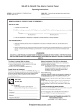
Reference, 24" stud centers
24"
(610 mm)
23-3/8" (594 mm)
23"
(584 mm)
3-7/8"
(98 mm)
1/2"
(13 mm)
Box width = 22-1/2" (572 mm)
Knockouts are provided for
nailing. Two on each side and
one each on top and bottom.
Conduit knockouts are provided on top and bottom
Box includes an 0.048 "
(1.2 mm) thick trim for semi-
flush mounting. Height and
width are same as door.
Drywall markers indicate
1/2" (13 mm) depth, two
on each side
Tyco is a registered trademark of Tyco International Services GmbH and is used under license. Simplex the Simplex logo, LifeAlarm, and WALKTEST are trademarks of Tyco
International Ltd. and its affiliates and are used under license. NFPA 70, NFPA 72, and National Fire Alarm Code are registered trademarks of the National Fire Protection
Association (NFPA).
Tyco Safety Products Westminster • Westminster, MA • 01441-0001 • USA S4005-0001-9 3/2009
www.tycosafetyproducts-usa-wm.com
© 2009 Tyco Safety Products Westminster. All rights reserved. All specifications and other information shown were current as of document revision date and are subject to change without notice.
Mounting Dimensions Reference
NOTE: A system ground must be provided for Earth Detection and transient protection devices. This connection
shall be made to an approved, dedicated Earth connection per NFPA 70, article 250, and NFPA 780.
/