Page is loading ...

DN2RT
DN3RT
DN5RT
PACKAGED REFRIGERATION FOR DN SERIES DOAS
Supplemental Manual
DN2RT SHOWN

1.800.627.4499
2
DOAS Packaged Refrigeration for DN-Series
WARNING
ARC FLASH AND ELECTRIC SHOCK HAZARD
Arc flash and electric shock hazard. Disconnect all electric
power supplies, verify with a voltmeter that electric power
is off and wear protective equipment per NFPA 70E before
working within electric control enclosure. Failure to comply
can cause serious injury or death.
Customer must provide earth ground to unit, per NEC, CEC
and local codes, as applicable.
Before proceeding with installation, read all instructions,
verifying that all the parts are included and check the name-
plate to be sure the voltage matches available utility power.
The line side of the disconnect switch contains live
high-voltage.
The only way to ensure that there is NO voltage inside the
unit is to install and open a remote disconnect switch and
verify that power is off with a volt meter. Refer to unit
electrical schematic. Follow all local codes.
CAUTION
RISK OF CONTACT WITH HOT SURFACES
The compressor and other electrical components are
extremely hot during operation. Allow sufficient time for
them to cool before working within the unit cabinet. Use
extreme caution and wear protective gloves and arm
protection when working on or near hot compressors,
associated piping and electrical components.
This equipment is to be installed by following Industry Best
Practices and all applicable codes. Any damage to
components, assemblies, sub-assemblies or the cabinet
which is caused by improper installation practices will void
the warranty.
IMPORTANT
Air ducts connecting this DOAS to the Occupied Space must
be installed in accordance with the Standards of the Nation-
al Fire Protection Agency for the installation of Air-
Conditioning and Ventilating Systems (Pamphlet No. 90A)
and Warm-Air Heating and Air-Conditioning Systems
(Pamphlet No. 90B).
IMPORTANT
IMPORTANT
This unit is not for use by persons (including children) with
reduced physical, sensory or mental capabilities, or lack
of experience or knowledge, unless they have been given
supervision or instruction concerning use of the appliance
by a person responsible for their safety.
Children should be supervised to ensure they do not play
with the appliance.
CAUTION
RISK OF ELECTRIC SHOCK OR EQUIPMENT DAMAGE
Whenever electrical wiring is connected, disconnected or
changed, the power supply to the DOAS and its controls
must be disconnected. Lock and tag the disconnect switch
or circuit breaker to prevent accidental reconnection of
electric power.
CAUTION
RISK OF COMPRESSOR DAMAGE
All compressors have an integral crankcase heater system
that must be enabled for at least SIX HOURS prior to
operation of the compressors.
The crankcase heater boils off any liquid refrigerant that
may be in the compressor. Liquid refrigerant cannot be
compressed and can cause damage to the compressor.
WARNING
COMPRESSED REFRIGERANT HAZARD
This unit contains compressed refrigerant (R-410A) in a
confined space. If the refrigerant tubing or other hardware is
heated too much, the possibility of an explosion exists.
If the tubing or other hardware is punctured or broken, a
sudden discharge of the R-410A refrigerant is likely. This
presents a danger of freeze burns or frostbite. When work-
ing with the refrigerant system, always wear appropriate
Personal Protective Equipment (PPE), as defined by OSHA.
Only EPA-certified technicians are to work on this com-
pressed refrigerant system.
If a refrigerant leak occurs, evacuate the area until the
refrigerant gas has dispersed. R-410A refrigerant gas may
be odorless.
CAUTION
RISK OF ELECTRIC SHOCK
VFDs use capacitors that retain a high-voltage charge even
after power is disconnected. When power to the DX unit
is disconnected, wait five minutes for the capacitors to
discharge themselves.

31.800.627.4499
Packaged Refrigeration for DN-Series DOAS
ATTENTION
RISQUE DE CHOC ÉLECTRIQUE
Les VFD utilisent des condensateurs qui conservent une
charge haute tension même après avoir coupé l’alimenta-
tion. Lorsque l’alimentation de l’unité DX est déconnectée,
attendez 5 minutes que les condensateurs se déchargent.
ATTENTION
RISQUE D’ENDOMMAGEMENT DU COMPRESSEUR
Tous les compresseurs ont un système de chauffage de
carter intégré qui doit être activé pendant au moins SIX
HEURES avant de faire fonctionner les compresseurs.
Le réchauffeur de carter évapore tout réfrigérant liquide qui
pourrait être dans le compresseur.
Les conduits d’air reliant ce DOAS à l’espace occupé doivent
être installés conformément aux normes de l’Agence na-
tionale de protection contre les incendies pour l’installation
de systèmes de climatisation et de ventilation (brochure n °
90A) et de systèmes de chauffage et de climatisation à air
chaud (Brochure n ° 90B).
IMPORTANT
Cet appareil doit être installé conformément aux meilleures
pratiques de l’industrie et à tous les codes applicables. Tout
dommage aux composants, assemblages, sous-ensembles
ou à l’armoire causé par des pratiques d’installation incor-
rectes annulera la garantie.
IMPORTANT
IMPORTANT
Cet appareil n’est pas destiné à être utilisé par des per-
sonnes (y compris des enfants) ayant des capacités
physiques, sensorielles ou mentales réduites, ou un manque
d’expérience ou de connaissances, sauf si elles ont reçu une
supervision ou des instructions concernant l’utilisation de
l’appareil par une personne responsable de leur sécurité.
Les enfants doivent être surveillés pour s’assurer qu’ils ne
jouent pas avec l’appareil.
AVERTISSEMENT
RISQUE D’ARC ÉLECTRIQUE ET DE CHOC ÉLECTRIQUE
Risque d’arc électrique et de choc électrique. Débranchez
toutes les alimentations électriques, vérifiez avec un volt-
mètre que l’alimentation électrique est coupée et portez un
équipement de protection conforme à la norme NFPA 70E
avant de travailler dans l’enceinte de commande électrique.
Le non-respect peut entraîner des blessures graves ou la
mort.
Le client doit fournir une mise à la terre à l’unité, conformé-
ment aux codes NEC, CEC et locaux, le cas échéant.
Avant de procéder à l’installation, lisez toutes les instruc-
tions, vérifiez que toutes les pièces sont incluses et vérifiez
la plaque signalétique pour vous assurer que la tension
correspond à l’alimentation secteur disponible.
Le côté ligne du sectionneur contient une haute tension
sous tension.
La seule façon de s’assurer qu’il n’y a pas de tension à l’in-
térieur de l’unité est d’installer et d’ouvrir un interrupteur de
déconnexion à distance et de vérifier que l’alimentation est
coupée avec un voltmètre. Se référer au schéma électrique
de l’unité. Suivez tous les codes locaux.
AVERTISSEMENT
RISQUE DE RÉFRIGÉRANT COMPRIMÉ
Cette unité contient du réfrigérant comprimé (R-410A) dans
un espace confiné. Si la tubulure de réfrigérant ou autre
matériel est trop chauffée, la possibilité d’une explosion
existe.
Si le tube ou autre matériel est perforé ou cassé, une
décharge soudaine de réfrigérant est probable. Cela
présente un risque de brûlures de gel ou d’engelures. Lor-
sque vous travaillez avec le système de réfrigération, portez
toujours un équipement de protection individuelle (EPI)
approprié, tel que défini par l’OSHA.
Seuls les techniciens certifiés EPA doivent travailler sur ce
système de réfrigérant comprimé.
En cas de fuite de réfrigérant, évacuez la zone jusqu’à la
dispersion du gaz réfrigérant. Le gaz réfrigérant R-410A
peut être inodore.
ATTENTION
RISQUE DE CONTACT AVEC DES SURFACES CHAUDES
Le compresseur et les autres composants électriques sont
extrêmement chauds pendant le fonctionnement. Lais-
sez-leur suffisamment de temps pour refroidir avant de
travailler dans l’armoire de l’unité.
Soyez extrêmement prudent et portez des gants de protec-
tion et une protection des bras lorsque vous travaillez sur
ou à proximité de compresseurs chauds, de la tuyauterie
associée et des composants électriques.
ATTENTION
RISQUE DE CHOC ÉLECTRIQUE OU DE DOMMAGES
MATÉRIELS
Chaque fois que le câblage électrique est connecté, dé-
connecté ou changé, l’alimentation électrique du DOAS et
ses commandes doivent être déconnectées. Verrouillez et
étiquetez le sectionneur ou le disjoncteur pour éviter toute
reconnexion accidentelle de l’alimentation électrique.

1.800.627.4499
4
DOAS Packaged Refrigeration for DN-Series
Cet appareil est destiné à la ventilation générale, pour
chauffage et au refroidissement uniquement. Ne pas utiliser
pour évacuer des matières et vapeurs dangereuses ou
explosives. Ne connectez pas cet équipement à des hottes
de cuisinière, des hottes ou des systèmes de collection des
produits toxiques.
IMPORTANT
IMPORTANT
Cette unité est destinée à la ventilation des structures finies
uniquement. Il ne doit pas être utilisé tant que la construc-
tion n’est pas terminée et que les débris de construction et
la poussière ne sont pas nettoyés de l’espace occupé.
IMPORTANT
Cette unité doit être utilisée à des altitudes allant jusqu’à
6999 pieds. Pour des élévations de 7000 pieds ou plus,
consultez l’usine.
IMPORTANT
This unit is for use at elevations up to 6999 feet. For
elevations 7000 feet or higher, consult the factory.
IMPORTANT
This unit is for ventilating finished structures only. It is not to
be used until after all construction has been completed and
construction debris and dust are cleaned from the
Occupied Space.
This unit is intended for general ventilating, heating, and
cooling only. Do not use to exhaust hazardous or explosive
materials and vapors. Do not connect this equipment to
range hoods, fume hoods or collection systems for toxics.
IMPORTANT
IMPORTANT
Cet appareil doit être installé dans un endroit non
accessible au grand public.
IMPORTANT
This appliance must be installed in a location not accessible
to the general public.

51.800.627.4499
Packaged Refrigeration for DN-Series DOAS
NOTICE
This manual contains space for maintaining written records of unit maintenance and/or
repairs. See Section 8.2 Maintenance Records. At the time the DOAS is commissioned, a
maintenance schedule should be developed by the user to incorporate monthly and seasonal
maintenance and include start up maintenance tasks as described in this manual.
Serial Number:
SO#:
Option Code:
ENERGY RECOVERY VENTILATOR
IPX4
Toll Free: 800-627-4499
WARNING
AVERTISSEMENT
Danger of electric shock.
Always disconnect power source before servicing.
Not For Use In Cooking Area.
Use Copper Supply Wires Only.
Danger de choc electrique. Toujours deconnector la
source d’alimentation avant les reparations.
Ne Pas Utilise Dans Une Zone De Cuisson.
Utiliser Des Fils D’Alimentation En Cuivre.
Motors Thermally Protected / Moteurs proteges thermiquement
POWER SUPPLY TO UNIT / Alimentation d’energie a l’unite
MOTOR/MOTEUR SPEC.
Voltage Minimum Circuit Amps
Max Overcurrent
Protection Device
Voltage (Qty) & kW/HP FLA
230V
200-240
[email protected] kW/3.6 hp
8.6-7.2
60 HZ 3~ Amp. Minimales de Circuit
Dispositif de protection maximum
contre les surintensites
(Qty) & kW/CV APC
Coil
Type Rows FPI Max Pressure (psi/MPa)
Motors Protected by
Variable Frequency Drives
Les moteurs protégés par la
frequence variable conduit
Dehumidify
Voltage (Qty) & kW/HP FLA
Re-heat
Heat
(Qty) & kW/CV APC
Type Rangee FPI Max. Pression (psi/MPa)
ELECTRIC HEATER/CHAUFFAGE ELECTRIQUE
Option Code:
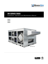
DN-3-JRTBH135P-RE3EN4---L
Voltage/Phase Amps kW
MODEL/MODELE: DN-3RT
Serial Number:
B21 00000
240V/3-Ph
36.1
15
SO#:
000000
JO#:
00000-0000
Label No: 133986_000
PACKAGED CONDENSING UNIT LABEL (TYP)
UNIT LABEL (TYP)
D -- RN P - --J T
PACKAGED CONDENSING UNIT
Class 1 Appliance
Waunakee, WI
Toll Free: 800-627-4499
REFRIGERANT/RÉFRIGÉRANT
CONDENSER COIL
Type
Charge (lbs/kg)
Max. Pressure (psi/MPa) Type Rows FPI Max. Pressure (psi/MPa)
1-Circ
2-Circ
Low Side
High Side
R410A
R410A
Type
Rangee
FPI
Max. Pression (psi/MPa)
Type
Charge (lbs/kg)
Max. Pression (psi/MPa)
COMPRESSOR/COMPRESSEUR
FAN MOTOR/MOTEUR de VENTILATEUR
Motors Protected by Variable Frequency Drives
Motors Thermally Protected
Voltage
(Qty) & kW
FLA
Voltage
(Qty) & kW
FLA
(Qty) & kW
APC
(Qty) & kW
APC
Les moteurs protégés par la frequence variable conduit
Moteurs Proteges Thermiquement
Motors Thermally Protected
Motors Protected by Variable Frequency Drives
Voltage
(Qty)
RLA
LRA
Voltage
(Qty) & kW
FLA
(Qty)
RLA
LRA
(Qty) & kW
APC
Moteurs Proteges Thermiquement
Les moteurs protégés par la frequence variable conduit
Label No: 133992_000
NOTE: This page
is to be completed
by the installing
contractor. The completed
document is to be turned
over to the owner after
start up.
READ AND SAVE THIS MANUAL/LIRE ET CONSERVER CE MANUEL
UNIT INFORMATION
Record information as shown below.
In the unlikely event that factory assistance is ever required, information located on the unit
label will be needed.
Locate the RenewAire unit label found on the outside of the unit.
NOTE: This information is for purposes of identifying the unit-specific option data from the
Option Code.
UNIT INFORMATION
NOTE: Digit 14 of
the unit configura-
tion code (Option
Code) indicates that the
unit has a Packaged
Refrigeration. For further
information on the DOAS
configuration code, see the
DN-Series Installation, Op-
eration, and Maintenance
Manual.
OWNER INFORMATION

1.800.627.4499
6
DOAS Packaged Refrigeration for DN-Series
TABLE OF CONTENTS
1.0 OVERVIEW 8
1.1 DESCRIPTION .........................................................8
1.2 SYSTEM SIZING ......................................................8
1.3 COOLING CAPACITY ................................................8
1.4 REHEAT CAPACITY ..................................................9
1.5 EVAPORATOR COIL OPERATION ...............................9
1.6 CONDENSING COIL OPERATION ...............................9
1.7 HOT GAS REHEAT COIL OPERATION .........................9
1.8 USER INTERFACE .................................................10
1.9 SAFETY FEATURES ...............................................10
2.0 COMPONENT DESCRIPTIONS 11
2.1 CABINET ..............................................................11
2.2 REFRIGERANT ......................................................12
2.3 POLYOLESTER OIL ................................................12
2.4 EVAPORATOR COIL ................................................12
2.5 CONDENSING COIL ...............................................12
2.6 CONDENSER FANS ...............................................13
2.7 COMPRESSORS ....................................................13
2.7.1 Compressor Crankcase Heaters .........................................14
2.7.2 Variable Frequency Drive (VFD) ......................................... 14
2.8 CONTROLLER .......................................................14
2.9 ELECTRONIC EXPANSION VALVE (EEV) ................... 15
2.10 FILTER-DRIER ..................................................... 15
2.11 SIGHT GLASS .....................................................16
2.12 PRESSURE LIMIT SWITCH ...................................16
2.13 TEMPERATURE SENSOR AND PRESSURE
TRANSDUCER .............................................................16
2.14 SERVICE PORT ....................................................17
2.15 HOT GAS REHEAT COIL (OPTION) ......................... 17
2.16 SUCTION ACCUMULATOR (OPTION) ......................17
2.17 MODULATING 3-WAY VALVE (OPTION) .................. 18
2.18 CHECK VALVE (OPTION) .......................................18
3.0 SHIPPING/RECEIVING/HANDLING 19
3.1 UNIT WEIGHTS AND DIMENSIONS .........................19
3.1.1 Unit Dimensions and Weight .............................................. 19
3.1.2 Shipping Dimensions and Weight ....................................... 19
3.1.3 DN-2-RT Packaged Corner Weights and COG Drawing ........20
3.1.4 DN-3-RT Packaged Corner Weights and COG Drawing .......21
3.1.5 DN-5-RT Packaged Corner Weights and COG Drawing .......22
4.0 UNIT PLACEMENT 23
4.1 UNIT PLACEMENT .................................................23
5.0 INSTALLATION 23
5.1 ELECTRICAL CONNECTIONS ..................................23
5.1.1 High-Voltage Power Supply ................................................23
5.1.2 Low-Voltage Power Supply ................................................23
5.2 CONDENSING UNIT WIRING SCHEMATIC ................24
5.2.1 Single-Circuit Wiring Schematic ........................................ 24
5.2.2 Two-Circuit Wiring Schematic ........................................... 26
5.3 P&I DIAGRAMS (PROCESS
AND INSTRUMENTATION) ............................................28
5.4 REFRIGERANT PRESSURE CHARTS .......................29
5.5 REFRIGERANT CHARGE CHARTS ...........................30
5.6. CHECK AND CHARGE REFRIGERANT ..................... 30
6.0 UNIT OPERATION 31
6.1 PRINCIPLE OF OPERATION ....................................31
6.1.1 Enable the Unit Locally ......................................................31
6.1.2 Checking for Critical Alarms .............................................. 32
6.1.3 Enable Signal from Main Controller .................................... 32
6.1.4 Viewing the Current State of the Unit .................................32
6.2 CONTROLLING THE UNIT ....................................... 32
6.2.1 Demand Calculation .......................................................... 33
6.2.2 Unit Running States —Single Compressor .........................33
6.2.3 Safety Timing ...................................................................34
6.2.4 Additional State for Second Compressor ...........................35
6.2.4.1 Relative Values to Illustrate Compressor
Staging Concept ........................................................................ 35
6.2.4.2 Example to Illustrate Compressor Staging Concept .........36
6.2.5 Compressor Oil Management ............................................38
6.2.6 Compressor Envelope Control ...........................................38
6.2.7 Superheat Control .............................................................39
6.2.8 Condenser Fan Control .....................................................39
6.3 CRANKCASE HEATER ............................................39
7.0 START UP 39
8.0 MAINTENANCE 40
8.1 MAINTENANCE SCHEDULE .................................... 40
8.1.1 Service Requirements .......................................................40
8.1.2 Commissioning Maintenance .............................................41
8.1.3 Start-of-Cooling Season Maintenance (Annual) .................. 41
8.1.4 End-of-Cooling Season Maintenance (Annual) ....................42
8.1.5 Periodic Maintenance (Monthly) .........................................42
8.2 MAINTENANCE RECORDS .....................................43
8.2.1 Commissioning Maintenance Log ......................................43
8.2.2 Start-of-Cooling Season Maintenance Log ........................44
8.2.3 End-of-Cooling Season Maintenance Log ..........................46
8.2.4 Periodic Maintenance (Monthly) ........................................48
8.2.5 Service Notes ...................................................................49

71.800.627.4499
Packaged Refrigeration for DN-Series DOAS
TABLE OF ILLUSTRATIONS
TABLE OF WIRING SCHEMATICS
TABLE OF P&I DIAGRAMS
Figure 1.8.0 Programmable Controller as Used for DOAS and
Packaged Refrigeration Control ..................................................10
Figure 2.1.0 DOAS with Packaged Refrigeration: Front View ........ 11
Figure 2.1.1 DOAS with Packaged Refrigeration: Back View ........ 11
Figure 2.1.2 DOAS with Packaged Refrigeration:
EA Fan Compartment ................................................................. 11
Figure 2.5.0 DOAS Condensing Coil Location .............................. 12
Figure 2.6.0 DOAS Condenser Fan (Shroud not shown) ............... 13
Figure 2.7.0 Variable-Speed and Fixed-Speed
Compressors (typ) ..................................................................... 13
Figure 2.7.1 Compressor Usage ..................................................13
Figure 2.7.2 External Crankcase Heater (typ) ..............................14
Figure 2.7.3 VFD and Fuse Block ................................................14
Figure 2.8.0 DOAS Controller and Refrigeration Controller .......... 15
Figure 2.9.0 Electronic Expansion Valve (EEV) ............................ 15
Figure 2.10.0 Filter-Drier............................................................ 15
Figure 2.11.0 Sight Glass ........................................................... 16
Figure 2.12.0 Pressure Limit Switch ........................................... 16
Figure 2.13.0 Temperature Sensor and Pressure Transducer .......16
Figure 2.14.0 Service Port (typ) .................................................. 17
Figure 2.15.0 HGRH Coil ............................................................ 17
Figure 2.16.0 Suction Accumulator ............................................. 17
Figure 2.17.0 Modulating 3-Way Valve ........................................18
Figure 2.18.0 Check Valve ..........................................................18
Figure 5.4.0 R-410A Saturation Properties .................................29
Figure 5.5.0 Oil Charge by Compressor Model ............................30
Figure 6.1.0 Enabling the Unit Locally .........................................31
Figure 6.1.1 Main Unit Status Screen ..........................................32
Figure 6.2.0 Main Unit Status Screen ......................................... 32
Figure 6.2.1 Variable Speed Compressor States .........................33
Figure 6.2.2 Unit Status Timer Screen ........................................33
Figure 6.2.3 General Compressor Settings .................................34
Figure 6.2.4 Compressor Safety Timing Settings ........................34
Figure 6.2.5 Staging of Second Compressor ...............................35
Figure 6.2.6 Second Compressor Staging Parameters ................35
Figure 6.2.7 Second Compressor Staging Diagram .....................35
Figure 6.2.8 Compressor Staging Example—
Increasing Demand ....................................................................37
Figure 6.2.9 Compressor Staging Example—
Decreasing Demand ..................................................................37
Figure 6.2.10 Oil Management Parameters ................................. 38
Figure 6.2.11 Envelope Alarm Timing Parameter .........................38
Figure 5.2.0 High Voltage Single-Circuit Wiring Schematic (typ) .. 24
Figure 5.2.1 Control Single-Circuit Wiring Schematic (typ) ..........25
Figure 5.2.2 High Voltage Two-Circuit Wiring Schematic (typ) .....26
Figure 5.2.3 Control Two-Circuit Wiring Schematic (typ) .............27
Figure 5.3.0 Variable Speed Circuit, No HGRH ............................28
Figure 5.3.1 Variable Speed Circuit, with HGRH ..........................28
Figure 5.3.2 Fixed Speed Circuit ................................................28
8.3 SERVICE PARTS .................................................... 50
9.0 TROUBLESHOOTING 50
9.1 ALARMS ............................................................... 50
9.2 SEQUENCE OF OPERATION ....................................56
9.3 BMS INTEGRATION ...............................................57
10.0 FACTORY ASSISTANCE 58
TABLE OF CONTENTS
Figure 6.2.12 Main Unit Status Screen—Shows
Envelope Zone ........................................................................... 38
Figure 6.2.13 Envelope Zones Defined ........................................38
Figure 6.2.14 Superheat Setpoint ............................................... 39
Figure 6.2.15 Electronic Expansion Valve Status Screen .............39
Figure 6.2.16 Electronic Expansion Valve Status Screen
Circuit 2 ....................................................................................39
Figure 6.2.17 Condenser Fan Parameters ................................... 39
Figure 8.1.0 Swing-Down Condenser Screen .............................. 42
Figure 8.3.0 Packaged DN Service Parts ....................................50
Figure 9.1.0 Device Management Alarms ....................................50
Figure 9.1.1 Refrigerant Probe Alarms ........................................ 51
Figure 9.1.2 General Maintenance Alarms .................................. 51
Figure 9.1.3 Refrigerant Circuit 1 Alarms ....................................52
Figure 9.1.4 Refrigerant Circuit 2 Alarms ....................................53
Figure 9.1.5 Copeland Compressor Alarms .................................53
Figure 9.1.6 Copeland Compressor Alarms Continued ................. 54
Figure 9.1.7 Siam Compressor Alarms ........................................54
Figure 9.1.8 Siam Compressor Alarms Continued .......................55
Figure 9.1.9 Siam Compressor Alarms Continued .......................56
Figure 9.3.0 BMS Points ............................................................ 57

1.800.627.4499
8
DOAS Packaged Refrigeration for DN-Series
1.0 OVERVIEW
1.1 DESCRIPTION
The DN-Series DOAS with Packaged Refrigeration option is a versatile, multi-application
system, available for all rooftop (RT) DOAS units that use three-phase power. It’s engineered to
function as a stand-alone system, providing conditioned Supply Air, on demand.
The Packaged Refrigeration system is classified by the Environmental Protection Agency (EPA)
as a Class II device.
All Packaged Refrigeration systems include a variable-speed compressor, condenser and
evaporator coils and a dedicated variable speed condenser fan(s). The Packaged Refrigeration
system may also include an optional Hot Gas Reheat Coil (HGRH) for humidity control. The
DN-Series DOAS with Packaged Refrigeration is fully wired and piped at the factory. It is fully
charged and tested prior to shipment.
The DN-Series with Packaged Refrigeration system includes a single variable-speed
compressor for small cooling capacity (single circuit), while larger cooling capacities have a
variable-speed compressor coupled with a fixed-speed compressor (two-circuit).
Control of the Packaged Refrigeration is accomplished by a dedicated refrigeration controller
connected to the RenewAire unit (DOAS) integrated programmable controller, via a serial cable.
The DOAS unit controller, with its integral sensors, monitors air conditions and then provides a
Call for Cooling to the refrigeration controller. The refrigeration controller monitors refrigerant
temperatures and pressures and controls the compressor(s) and the condenser fan(s) to
maintain the desired supply air temperature. The Call for Cooling is based on either Supply Air
or Return Air temperature.
When an HGRH coil is ordered, the modulating HGRH function is controlled directly by the DOAS
unit Integrated Programmable Controls (IPC).
The 24VAC needed by the refrigeration controller is provided by a step-down transformer
located in the unit E-box, while high-voltage power for the compressors, fans and VFDs are
wired directly to the unit main disconnect switch.
The DN unit with Packaged Refrigeration utilizes the same airflow configurations as DN-Series
Rooftop Units. The airflow configuration is indicated by Digit 10 of the unit configuration code.
This manual is to be used in conjunction with the DN Series DOAS Rooftop Installation,
Operation and Maintenance Manual and the DN Series Integrated Programmable Controls
User Manual.
OVERVIEW
1.2 SYSTEM SIZING
The refrigeration system is sized to meet the customer-specified operating conditions. Much of
the system sizing is accomplished automatically within RenewAire’s CORES unit configuration
software based on customer design conditions. The evaporator coil capacity is determined
based on design conditions and a compressor is selected to meet the cooling capacity. Then,
the condenser coil capacity is then designed to match the evaporator coil and compressor.
Piping sizes are automatically selected along with the additional refrigeration components
required for the system.
1.3 COOLING CAPACITY
Each DOAS model has multiple cooling capacities that can be specified. Cooling capacity is
determined by matching the customer’s design conditions to a combination of evaporator and
condenser coils, compressor(s) and fans. Each DOAS model has several different component
combinations available to attain the required cooling capacity, taking into consideration the
expected operating conditions.
DN-2: 2–10 tons cooling capacity
DN-3: 3.5–20 tons cooling capacity
DN-5: 5.5–30 tons cooling capacity
NOTE: This manual
is for the Pack-
aged Refrigeration
system as used on
RT model (rooftop)
DOAS units.

91.800.627.4499
Packaged Refrigeration for DN-Series DOAS
OVERVIEW
1.4 REHEAT CAPACITY
1.5 EVAPORATOR COIL OPERATION
1.6 CONDENSING COIL OPERATION
1.7 HOT GAS REHEAT COIL OPERATION
Each DOAS model has multiple reheat capacities that can be specified. Reheat capacity is
determined by matching the expected operating conditions of the unit to the customer’s desired
leaving air temperature of the Supply Air.
Liquid refrigerant enters the evaporator coil at the Evaporator Temperature (~40°F) and at a low
pressure (~119 psig). Heat from the unit Fresh Air transfers to the refrigerant. Due to the heat
absorption, the refrigerant changes from a liquid to a vapor as it flows through the evaporator
coil. By the time the refrigerant leaves the evaporator coil, it is all vapor and is at the Superheat
Temperature, which the Evaporator Temperature plus the degrees of Superheat. The refrigerant
vapor, at a low pressure, is then drawn into the compressor.
Refrigerant vapor is discharged from the compressor and enters the condenser coil at the
Condensing Temperature (~130°F) and at high pressure (~477 psig). Heat from the refrigerant
transfers to the ambient air as it is pulled through the condenser coil by the condenser fan. Due
to the heat rejection, the refrigerant changes from a vapor to a liquid as it flows through the
condenser coil. By the time the refrigerant leaves the condenser coil it is a liquid and is at the
Liquid Temperature, which is the Condensing Temperature minus the Sub-cooling Temperature.
The hot gas reheat coil is basically a condensing coil that is located next to the evaporator coil,
on the downstream side. It receives a regulated amount of refrigerant vapor at condensing
temperature and rejects heat into the cooled Supply Air airstream. The amount of the refrigerant
vapor entering the HGRH coil is controlled by a motorized 3-way modulating valve that is
controlled by the DOAS IPC. The amount of heat rejected into the Supply Air airstream leaving
the evaporator coil is sufficient to raise the Supply Air temperature to the desired temperature.
Because of the heat that is rejected by the HGRH coil, the refrigerant changes from a vapor to a
liquid before merging with the liquid refrigerant leaving the condensing coil.

1.800.627.4499
10
DOAS Packaged Refrigeration for DN-Series
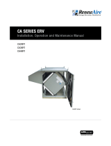
1.8 USER INTERFACE
The user interface for the refrigeration system is the keypads and data screens found on the
faces of both the primary DOAS Controller and the secondary refrigeration controller. The two
controllers are connected by a serial cable. The DOAS controller requires various configuration
settings to operate (at the primary user interface), and will then provide a Call for Cooling signal
to the secondary refrigeration controller. The refrigeration controller also requires configuration
settings (configured at the factory and accessible from the primary DOAS controller). The DOAS
controller is connected to an expansion board and are located in the main unit electrical box.
The refrigeration controller is mounted in the compressor compartment near the compressor
Variable Frequency Drive (VFD) (refrigeration controller does not normally need access as
interface is with the primary DOAS controller).
For ease of use, both the DOAS controller and the refrigeration controller may be connected to
an optional Remote User Terminal (RUT) or to a laptop computer. See the DN-Series Integrated
Programmable Controls User Manual for more information including password.
1.9 SAFETY FEATURES
u Step-down power supply transformers have an integral circuit breaker that will trip in case
of overload.
u Each phase of the electrical power supply is fused (optional).
u VFDs are fused, which protects the VFD and the driven variable-speed compressor.
u High pressure limit switch with manual reset for variable-speed and fixed
speed compressors.
u Motor starter with overload relay for fixed-speed compressors.
FIGURE 1.8.0 PROGRAMMABLE CONTROLLER AS USED FOR DOAS AND PACKAGED REFRIGERATION CONTROL
OVERVIEW

111.800.627.4499
Packaged Refrigeration for DN-Series DOAS
2.0 COMPONENT DESCRIPTIONS
2.1 CABINET
The DN DOAS with Packaged Refrigeration varies from the standard DOAS unit. Access
panels are added to the back of the cabinet and the metal panel that separates the EA fan
compartment from the controls compartment includes a removable access panel, for servicing
the compressor compartment.
In addition, a condenser fan module is added to the outside of the unit that contains the
condenser coil with condenser fan, mounted on top of the condenser hood.
REMOVABLE ACCESS PANEL
(FOR SERVICING PACKAGED
REFRIGERATION SYSTEM)
CONDENSER
MODULE
ACCESS PANELS
(REMOVABLE
PANELS NOT
SHOWN)
FIGURE 2.1.0 DOAS WITH PACKAGED REFRIGERATION: FRONT VIEW
FIGURE 2.1.1 DOAS WITH PACKAGED REFRIGERATION: BACK VIEW
FIGURE 2.1.2 DOAS WITH PACKAGED REFRIGERATION: EA FAN COMPARTMENT
COMPONENT DESCRIPTION

1.800.627.4499
12
DOAS Packaged Refrigeration for DN-Series
2.2 REFRIGERANT
2.3 POLYOLESTER OIL
2.4 EVAPORATOR COIL
2.5 CONDENSING COIL
The refrigerant used in all Packaged Refrigeration systems is R-410A. There are minimal
hazards involved in its use. It is a non-flammable, colorless, volatile liquid with a faint sweetish
odor. It may also be odorless. There are two primary hazards involved in its use: since it will
displace air, it could cause a reduction in available oxygen levels, causing dizziness. The second
issue is that if it is accidentally released, the vapor stream could cause freeze burns
or frostbite.
Polyolester Oil (or POE Oil) is used as a synthetic lubricant for the compressors. It is fully
compatible with the R-410A refrigerant.
The evaporator coil is a standard RTFP (round copper tubes with pressed aluminum fins) coil
located in the coil compartment. The evaporator coil is sized to meet the cooling requirements
of the unit. Liquid refrigerant is changed to a gas as it enters the coil. When the gas expands
(evaporates), it readily absorbs the available heat energy, from the Fresh Air airstream.
Condensing coils, sometimes referred to just as “condensers,” are located in the condenser
module attached to the outside of the DOAS unit. They are standard RTFP coils. The
compressors compress the refrigerant gas returning from the evaporator coil and push it into
the condenser coil, where it changes back to a liquid as it cools. Ambient air is drawn through
the condenser coils, allowing the hot refrigerant to reject its heat energy.
CAUTION
RISK OF ALLERGIC REACTION
Polyolester oil may cause an allergic skin reaction. Use Personal Protective Equipment (PPE)
such as gloves and face shield when handling POE oil. Clean up any spills immediately.
CONDENSING COIL LOCATED
ABOVE INTAKE SCREEN
FIGURE 2.5.0 DOAS CONDENSING COIL LOCATION
COMPONENT DESCRIPTION
WARNING
COMPRESSED REFRIGERANT HAZARD
This unit contains compressed refrigerant (R-410A) in a confined space. If the refrigerant
tubing or other hardware is heated too much, the possibility of an explosion exists.
If the tubing or other hardware is punctured or broken, a sudden discharge of the R-410A
refrigerant is likely. This presents a danger of freeze burns or frostbite. When working with
the refrigerant system, always wear appropriate PPE, as defined by OSHA.
Only EPA-certified technicians are to work on this compressed refrigerant system.
If a refrigerant leak occurs, evacuate the area until the refrigerant gas has dispersed. R-410A
refrigerant gas may be odorless.

131.800.627.4499
Packaged Refrigeration for DN-Series DOAS
2.6 CONDENSER FANS
Condenser fans are variable-speed, EC type unless the unit is 575VAC, where the condenser
fans are run by a VFD. DN-2 DOAS units have one condenser fan, while DN-3 and DN-5 units
have two. The fans are controlled by the refrigeration controller. Both fans run simultaneously,
at the same speed. The fans are always located on top of the condenser module.
FIGURE 2.6.0 DOAS CONDENSER FAN (SHROUD NOT SHOWN)
COMPONENT DESCRIPTION
2.7 COMPRESSORS
The compressors used in all units are scroll-type. If there is only one compressor, it is a
variable speed scroll compressor. DOAS units requiring greater cooling capacity will have a
second compressor, but it is fixed-speed. Variable-speed compressors use a VFD to drive them
at the correct speed, while fixed-speed compressors use contactors to turn them ON and OFF.
The contactors are mounted in an electrical box on the wall in the compressor compartment,
near the refrigeration controller.
Several SIAM and Copeland models are used for variable speed and three Copeland models are
used for fixed speed.
FIGURE 2.7.0 VARIABLE-SPEED AND FIXED-SPEED COMPRESSORS (TYP)
Tonnage EEV 208/230 VAC 460 VAC 575 VAC
3E2V24 ANB33FBSMT ANB33FLGMT ZPV0282E
5E2V30 ANB52FKKMT ANB52FKPMT ZPV0382E
6E2V30 ANB66FVCMT ANB66FVQMT N/A
7E2V30 ANB78FVCMT ANB78FVQMT N/A
8E2V35 N/A ANB87FVLMT N/A
15 E3V45 ZPV0662E ZPV0662E ZPV0662E
20 E3V45 ZPV0962E ZPV0962E ZPV0962E
24 (15 + 9) E3V45/ E2V35 ZPV066 + ZP104K ZPV066 + ZP104K ZPV066 + ZP104K
30 (20 + 10) E3V45/ E2V35 ZPV096 + ZP122K ZPV096 + ZP122K ZPV096 + ZP122K
35 (20 + 15) E3V45/ E3V45 ZPV096 + ZP182K ZPV096 + ZP182K ZPV096 + ZP182K
FIGURE 2.7.1 COMPRESSOR USAGE

1.800.627.4499
14
DOAS Packaged Refrigeration for DN-Series
2.8 CONTROLLER
The Packaged Refrigeration system has its own secondary refrigeration controller that is, in
turn, controlled by the primary DOAS Controller. The refrigeration controller is responsible for
monitoring temperature and pressure readings, as measured by the sensors in the refrigeration
piping. When the refrigeration controller receives a Call for Cooling from the primary DOAS
controller, the refrigeration controller assesses current data from the temperature and pressure
sensors and, when appropriate, will turn on the compressor(s) and condenser fan(s) to control
their speed.
VFD FOR VARIABLE-SPEED
COMPRESSOR
VFD FUSE BLOCK
FIGURE 2.7.3 VFD AND FUSE BLOCK
COMPONENT DESCRIPTION
2.7.2 Variable Frequency Drive (VFD)
All variable-speed compressors are driven by a VFD, sometimes referred to as a “drive.” There
is always a single drive installed, found on the wall of the compressor compartment. The most
commonly-used drive is a Carel Power+Speed Drive. This drive is used with all SIAM variable-
speed compressors. Whenever Copeland scroll variable-speed compressors are used, an
Emerson Drive is used. Operating parameters for the specific compressor are built into the
drive firmware. The VFD receives a Call for Cooling from the Refrigeration controller and the
VFD then provides power to the compressor at a frequency that will satisfy the Call for Cooling.
When the Refrigeration controller is properly configured for the system type, it automatically
applies correct compressor operating parameter settings. Do not override the factory-installed
parameters.
VFDs are always fused. The fuse block is located in an electrical box near the VFD.
2.7.1 Compressor Crankcase Heaters
All compressors have either an internal or an external crankcase heater that operates whenever
power is supplied to the DOAS and the disconnect switch is turned ON. Only fixed-speed
compressors have external crankcase heaters. Crankcase heaters prevent refrigerant migration
and the resulting “liquid slugging” when the compressor is turned on.
CAUTION
RISK OF COMPRESSOR DAMAGE
All compressors must have power applied to the crankcase heater for a minimum of SIX
HOURS prior to operation. Failure to do so may result in the compressor not starting.
FIGURE 2.7.2 EXTERNAL CRANKCASE HEATER (TYP)

151.800.627.4499
Packaged Refrigeration for DN-Series DOAS
FIGURE 2.8.0 DOAS CONTROLLER AND REFRIGERATION CONTROLLER
REFRIGERATION CONTROLLER IN
COMPRESSOR COMPARTMENT
DOAS CONTROLLER IN E-BOX
COMPONENT DESCRIPTION
2.10 FILTER-DRIER
2.9 ELECTRONIC EXPANSION VALVE (EEV)
There is at least one electronic expansion valve (EEV) installed in each Packaged Refrigeration
unit. This EEV regulates the flow of refrigerant into the evaporator coil. It is always located on
the variable-speed compressor circuit and is controlled by the refrigeration controller. See the
P&I diagrams in Section 5.3 of this manual.
A second EEV is installed for a fixed speed compressor circuit. It is controlled by the
refrigeration controller. Its control signal is generated by the refrigeration controller and passed
to the main controller, where it is sent to the valve.
A filter-drier is provided on the liquid line between the condenser coil and the evaporator coil. It
is a permanent device that filters small amounts of contaminants and any remaining moisture
that may be present in the refrigerant. Under normal operation the filter drier does not require
any maintenance.
FIGURE 2.9.0 ELECTRONIC EXPANSION VALVE (EEV)
FIGURE 2.10.0 FILTER-DRIER

1.800.627.4499
16
DOAS Packaged Refrigeration for DN-Series
2.12 PRESSURE LIMIT SWITCH
2.13 TEMPERATURE SENSOR AND PRESSURE TRANSDUCER
Temperature sensors and pressure transducers are both passive devices that provide data to
the refrigeration controller. The pressure transducers are screwed onto a service port to enable
reading of refrigerant pressure while the temperature sensors are attached to the exterior of the
copper piping. A set of temperature sensor and pressure transducer is mounted on both the low
pressure side and high pressure side of the compressor(s).
TEMPERATURE SENSOR
PRESSURE TRANSDUCER
A high pressure limit switch is provided for the variable speed compressor, and for the fixed
speed compressor when present. The limit switch is on the discharge line, just after the
compressor. When the refrigerant discharge pressure exceeds the pre-set limit, the switch will
trip and shut down the compressor. The limit switch has a manual reset button.
FIGURE 2.12.0 PRESSURE LIMIT SWITCH
FIGURE 2.13.0 TEMPERATURE SENSOR AND PRESSURE TRANSDUCER
COMPONENT DESCRIPTION
2.11 SIGHT GLASS
Sight glasses are installed in the refrigeration piping to reveal the presence of moisture. If
there is no moisture present, the colored dot in the center of the sight glass will be green and if
moisture is present, the dot will turn yellow.
FIGURE 2.11.0 SIGHT GLASS

171.800.627.4499
Packaged Refrigeration for DN-Series DOAS
COMPONENT DESCRIPTION
2.14 SERVICE PORT
Service ports are installed in several locations in the Packaged Refrigeration piping. They are
standard Schrader valves.
FIGURE 2.14.0 SERVICE PORT (TYP)
2.16 SUCTION ACCUMULATOR (OPTION)
A suction accumulator is a refrigerant buffering reservoir, installed on the refrigerant line
between the evaporator coil and the variable speed compressor. It is always and only used
on systems having optional Hot Gas Reheat. The accumulator intercepts any slugs of liquid
refrigerant or oil and provides a space for the refrigerant to change back to a gas. Any oil that
accumulates is metered back into the system.
2.15 HOT GAS REHEAT COIL (OPTION)
The optional Hot Gas Reheat coil is located in the coil compartment, just downstream from
the cooling coil. It is controlled by the DOAS unit controller. It receives a variable amount of
refrigerant from the modulating 3-way valve.
FIGURE 2.15.0 HGRH COIL
FIGURE 2.16.0 SUCTION ACCUMULATOR

1.800.627.4499
18
DOAS Packaged Refrigeration for DN-Series
2.17 MODULATING 3-WAY VALVE (OPTION)
2.18 CHECK VALVE (OPTION)
A motorized three-way modulating valve is provided for all Packaged Refrigeration units having
optional Hot Gas Reheat. The valve diverts a variable amount of hot refrigerant leaving the
compressor, to the HGRH coil. The valve is controlled by the DOAS IPC.
A check valve is installed in all Packaged Refrigeration units having optional HGRH. It is located
on the HGRH coil discharge line before it re-enters the refrigerant line between the condenser
coil and the evaporator coil. The check valve prevents backflow of the refrigerant through the
HGRH coil. See the P&I diagrams in Section 5.3 of this manual.
FIGURE 2.17.0 MODULATING 3-WAY VALVE
FIGURE 2.18.0 CHECK VALVE
COMPONENT DESCRIPTION

191.800.627.4499
Packaged Refrigeration for DN-Series DOAS
SHIPPING/RECEIVING
3.0 SHIPPING/RECEIVING/HANDLING
DOAS units that are equipped with the Packaged Refrigeration option are substantially larger
and heavier than those that do not have the option. They are shipped with condenser/condenser
fan assemblies installed. EA and OA hoods are shipped loose.
See the unit IOM for further instructions on rigging the unit for hoisting. See Section 3.1.2 in
this manual for further information on shipping weights and dimensions. See Section 3.1.3,
3.3.4, and 3.1.5 for Center of Gravity (COG) drawing with corner weights.
3.1 UNIT WEIGHTS AND DIMENSIONS
3.1.1 Unit Dimensions and Weight
3.1.2 Shipping Dimensions and Weight
DN-2-RT PKGD with 1" cabinet walls
Dimensions: 189 3/8" L x 76 3/4" W x 76 3/4" H
Weight Range: 2450–3150 lbs.
DN-2-RT PKGD with 2" cabinet walls
Dimensions: 191 3/8" L x 78 3/4" W x 77 3/4" H
Weight Range: 2550–3275 lbs.
DN-3-RT PKGD with 1" cabinet walls
Dimensions: 210 3/4" L x 106 1/8" W x 78 1/2" H
Weight Range: 3400–4900 lbs.
DN-3-RT PKGD with 2" cabinet walls
Dimensions: 212 3/4" L x 108 3/4" W x 79 1/2" H
Weight Range: 3525–5100 lbs.
DN-5-RT PKGD with 1" cabinet walls
Dimensions: 247 3/8" L x 126 3/8" W x 95" H
Weight Range: 4825–6600 lbs.
DN-5-RT PKGD with 2" cabinet walls
Dimensions: 249 3/8" L x 128 3/8" W x 96 1/4" H
Weight Range: 5000–6800 lbs.
DN-2-RT PKGD with 1" cabinet walls
Dimensions: 165 3/4" L x 90" W x 81 3/4" H
Weight Range: 2625–3375 lbs.
DN-2-RT PKGD with 2" cabinet walls
Dimensions: 167 3/4" L x 90" W x 82 3/4" H
Weight Range: 2725–3500 lbs.
DN-3-RT PKGD with 1" cabinet walls
Dimensions: 187 1/8" L x 90" W x 83 1/2" H
Weight Range: 3575–5175 lbs.
DN-3-RT PKGD with 2" cabinet walls
Dimensions: 189 1/8" L x 90" W x 84 1/2" H
Weight Range: 3700–5375 lbs.
DN-5-RT PKGD with 1" cabinet walls
Dimensions: 219 3/4" L x 100 1/4" W x 100" H
Weight Range: 5050–6950 lbs.
DN-5-RT PKGD with 2" cabinet walls
Dimensions: 221 3/4" L x 101 1/4" W x 101 1/4" H
Weight Range: 5225–7150 lbs.
The unit weights and dimensions vary based on configuration of the unit and options selected.
The following sections provide weight ranges for units with packaged refrigeration.

1.800.627.4499
20
DOAS Packaged Refrigeration for DN-Series
3.1.3 DN-2-RT Packaged Corner Weights and COG Drawing
SHIPPING/RECEIVING
MODELS L W A B UNIT LF LR RR RF
LR
RR ERV+Coil 95.26 48 58.255 24.271 2500 756 773 491 480
ERV+Coil+EH 119.89 48 58.98 23.48 2775 697 668 690 720
ERV+Coil+GH 119.89 48 61.74 22.95 2975 800 733 690 753
ERV+Coil+ST 119.89 48 60.87 22.63 2875 772 688 667 748
MODELS L W A B UNIT LF LR RR RF
ERV+Coil 97.26 50 59.255 25.271 2610 786 804 515 504
ERV+Coil+EH 121.89 50 59.98 24.48 2900 728 699 721 752
LF
RF ERV+Coil+GH 121.89 50 62.74 23.95 3100 831 764 721 784
ERV+Coil+ST 121.89 50 61.87 23.63 3000 803 720 698 779
OPTIONS
RECIRC
VFD
UNIT
25
150
CenterofGravity"A"and"B"Dimensions+/‐2"
AddtheadditionalweightsforoptionstotheUnitWeightstodetermineUnitandCornerweightsforaspecificunit.
DN‐2‐RTPKGD1"CABINETUNITWEIGHTS(LBS)
CenterofGravity"A"and"B"Dimensions+/‐2"
DN‐2‐RT2"PKGDCABINETUNITWEIGHTS(LBS)
DashedlineisODofunitbase.
ADDITIONALWEIGHTSFOROPTIONS(LBS)
DN‐2‐RTPKGD
MODELS L W A B UNIT LF LR RR RF
LR RR ERV
+Coil 95.26 48 58.255 24.271 2500 756 773 491 480
ERV+Coil+EH 119.89 48 58.98 23.48 2775 697 668 690 720
ERV+Coil+GH 119.89 48 61.74 22.95 2975 800 733 690 753
ERV+Coil+ST 119.89 48 60.87 22.63 2875 772 688 667 748
MODELS L W A B UNIT LF LR RR RF
ERV+Coil 97.26 50 59.255 25.271 2610 786 804 515 504
ERV+Coil+EH 121.89 50 59.98 24.48 2900 728 699 721 752
LF RF ERV
+Coil+GH 121.89 50 62.74 23.95 3100 831 764 721 784
ERV+Coil+ST 121.89 50 61.87 23.63 3000 803 720 698 779
OPTIONS
RECIRC
VFD
UNIT
25
150
CenterofGravity"A"and"B"Dimensions+/‐2"
AddtheadditionalweightsforoptionstotheUnitWeightstodetermineUnitandCornerweightsforaspecificunit.
DN‐2‐RTPKGD1"CABINETUNITWEIGHTS(LBS)
CenterofGravity"A"and"B"Dimensions+/‐2"
DN‐2‐RT2"PKGDCABINETUNITWEIGHTS(LBS)
DashedlineisODofunitbase.
ADDITIONALWEIGHTSFOROPTIONS(LBS)
DN‐2‐RTPKGD
/