Page is loading ...

Carel c.pCO Mini Carel c.pCOe Expansion Board
DOAS INTEGRATED PROGRAMMABLE CONTROLS
Installation, Operation and Maintenance Manual
FOR COMMERCIAL DN-SERIES

1.800.627.4499
DN-Series Integrated Programmable ControlsDOAS
2
This manual applies to DN-Series DOAS units with controls version 3.xx.xx. For previous
versions refer to the older manual. The version number can be seen on the splash screen when
the unit power is cycled.
Newer units also have this version information in the Unit Status screens.

31.800.627.4499
DN-Series Integrated Programmable Controls DOAS
WARNING
ARC FLASH AND ELECTRIC SHOCK HAZARD
Microprocessor controllers as discussed in this manual are
typically installed in a control panel where high voltages are
present. Whenever accessing any controller, disconnect all
electric power supplies, verify with a voltmeter that electric
power is OFF and wear protective equipment per NFPA
70E when working within the electric enclosure. Failure to
comply can cause serious injury or death.
The line side of the disconnect switch contains live
high-voltage.
The only way to ensure that there is NO voltage inside the unit
is to install and open a remote disconnect switch and verify
that power is off with a voltmeter. Refer to unit
electrical schematic.
Follow all local codes.
CAUTION
RISK OF COMPUTER SECURITY BREACH
This controller is capable of being connected to a network.
Any device that is connected to a network is susceptible to
unauthorized access and hostile activities. It is the owner’s
responsibility to determine acceptable risks and to safeguard
the security of the controller and all connected devices.
IMPORTANT
This controller is only for use in protected environments. It
is not to be exposed to the weather or exposed to extremes
in temperature.
IMPORTANT
Only persons who have been properly trained and authorized
are to access the DOAS control panel and the controller.
Changes to the controller settings are to be made only by
trained and authorized personnel. All changes to the controller
settings are to be documented in the Controller Maintenance
Records section in this manual.
IMPORTANT
This control system is subject to periodic updates in firmware
and the User Manual itself. Please contact RenewAire Support
at RenewAireSupport@RenewAire.com to determine if you
have the most recent manual and firmware.
IMPORTANT
Risk of degraded unit efficiency. Improper adjustment of
unit setpoints may result in the DOAS operating inefficiently.
Improper selection of Input Offsets may cause incorrect or
inefficient operation of the DOAS.
CAUTION
RISK OF ELECTRIC SHOCK OR EQUIPMENT DAMAGE
Whenever electrical wiring is connected, disconnected or
changed, the power supply to the DOAS and its controls
must be disconnected. Lock and tag the disconnect switch
or circuit breaker to prevent accidental reconnection of
electric power.

1.800.627.4499
DN-Series Integrated Programmable ControlsDOAS
4
NOTICE
This manual contains space for maintaining written records of settings and changes. See
Section 15, Maintenance Records. At the time the DOAS is commissioned, a complete record
(an operating parameter file) should be made of all settings, to include setpoints and offsets.
Whenever changes are made to the controller data points, those changes should be
recorded, along with the reason for the change.
Information that is recorded is specific to just one DOAS or controller. If additional
controllers are being documented, please make copies of these pages and identify each
copy by its unit tag.
NOTICE
Whenever an operating parameter file is created in the controller internal memory, a backup
file should be created on an external memory device and stored in some convenient place.
READ AND SAVE THIS MANUAL/LIRE ET CONSERVER CE MANUEL
NOTE: This page
is to be completed
by the installing
contractor. The
completed document is
to be turned over to the
owner after start up.
NOTE: When the
DOAS is first con-
nected to electric
power, the unit is to be
started only for purposes
of testing correct wiring
and to verify correct
operation of the fans
and dampers.
D - -- -N J -
Configuration Code:
Serial Number:
SO #:
UNIT INFORMATION
Record information as shown below.
In the unlikely event that factory assistance is ever required, information located on the unit
label will be needed.
Locate the RenewAire unit label found on the outside of the unit.
NOTE: This information is for purposes of identifying the unit-specific option data from the
Configuration Code.
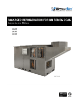
UNIT INFORMATION
UNIT LABEL (TYPICAL)
OWNER INFORMATION

51.800.627.4499
DN-Series Integrated Programmable Controls DOAS
CONFIGURATION CODE
Refer to Section 16, Reference in this manual for the full interpretation of the
configuration code.
MODEL NUMBER D N - - J
DIGIT NUMBER 1 2 3 4 5 6 7 8 9 10 11 12 13 14 15 16 17 18 19 20 21 22 23 24 25
OWNER INFORMATION
DN MODELS
CONFIGURATION GUIDE
Note: Not all options are available on every model.
For Technical Support E-mail: [email protected]
To Place an Order E-mail: [email protected]
MODEL NUMBER D N - - J - - -
DIGIT NUMBER 1 2 3 4 5 6 7 8 9 10 11 12 13 14 15 16 17 18 19 20 21 22 23 24 25
Digits 1–5: Model
Digit 17: Heating (See Restrictions 3, 16, & 21)
"DN-2-" = 1,650 CFM
"-" = None
"DN-3-" = 3,300 CFM
"E" = Electric Heater
"DN-5-" = 4,950 CFM
"G" = Gas Heat Module
"P" = Heat Pump
Digit 6: Exchanger Type "S" = Steam
"J" = G5 Core "H" = Hot Water
Digits 7–8: Location (See Restriction 1) Digit 18: Heater Size (See Restrictions 4, 8, 9, 10, 11, 12, 13, & 14)
"IN" = Indoor "-" = None
"RT" = Rooftop "1" = Gas 50 MBH or Electric 5kW
"2" = Gas 75 MBH or Electric 10kW
Digit 9: SA Fan Location (See Restrictions 18 & 19) "3" = Gas 100 MBH or Electric 15kW
"B" = Before Coil (Standard) "4" = Gas 125 MBH or Electric 20kW
"A" = After Coil "5" = Gas 150 MBH or Electric 25kW
"6" = Gas 200 MBH or Electric 30kW
Digit 10: Orientation "7" = Gas 250 MBH or Electric 40kW
"A", "B", "C", "D", "E", "G", "J", "K", "L", "M", "N", "P", (Indoor Units ONLY) "8" = Gas 300 MBH or Electric 50kW
"V", "H", "R", "F" "9" = Gas 350 MBH or Electric 60kW
Digit 11: Insulation Digit 19: Fan Control (See Restrictions 5 & 6)
"1" = 1 inch "E" = ECM
"2" = 2 inch with Thermal Break "V" = VFD
Digit 12: Phase (See Restriction 15) Digit 20: Unit Fusing
"1" = Single Phase "N" = Non-Fused (Standard)
"3" = Three Phase "F" = Fused
Digit 13: Voltage (See Restrictions 2 & 7) Digit 21: Unit Control Enhancements
"3" = 208V "2" = Premium Controls without BacNet
"4" = 460V "4" = Premium Controls with BacNet
"5" = 230V
"8" = 575V Digit 24: Customization
"-" = None
Digit 14: Refrigerant Type (See Restriction 20) "P" = Standard Paint, No Customizations
"-" = None "X" = Custom Unit, No Paint
"P" = Packaged "Z" = Custom Unit and Paint
Digit 16: Cooling Digit 25: Safety Listing (See Restriction 17)
"-" = None "L" = Listed
"C" = Chilled Water "N" = Non-Listed
"D" = Direct Expansion
"H" = Heat Pump
"P" = Heat Pump + Hot Gas Reheat (HGRH)
"R" = Direct Expansion + Hot Gas Reheat (HGRH)
*NOTES:
Digits 3, 5, 15, 22, and 23 are not used in these models.
Restrictions:
1: Location Code "RT" only available with Orientation Codes "H", "V", "R" & "F".
2: Voltage Code "4" & "8" only available with Phase Code "3".
3: Heating Code "P" only available with Cooling Codes "H" or "P".
4: Heater Size Option only available with Heating Codes "E" & "G".
5: Fan Control Code "E" only available with Voltage Codes "3", "4", & "5".
6: Fan Control Code "V" only available with Phase Code "3".
7: Voltage Code "8" only available with Fan Control "V".
8: Heater Size Codes "8" & "9" are not available when Model Code is "DN-2-" and Heating Code is "E".
9: Heater Size Codes "8" & "9" are not available when Model Code is "DN-3-" or "DN-5-" and Unit Voltage Code is "3" or "5" and Fan Control Code is "V" and Heating Code is "E".
10: Heater Size Code "8" is not available when Model Code is "DN-5-" and Unit Voltage Code is "3" and Fan Control Code is "E" and Heating Code is "E".
11: Heater Size Code "9" is not available when Model Code is "DN-3-" or "DN-5-" and Unit Voltage Code is "3" or "5" and Fan Control Code is "E" and Heating Code is "E".
12: Heater Size Code "7" is not available when Model Code is "DN-5-" and Unit Voltage Code is "3" or "5" and Fan Control Code is "V" and Heating Code is "E".
DN MODELS
CONFIGURATION GUIDE
Note: Not all options are available on every model.
For Technical Support E-mail: [email protected]
To Place an Order E-mail: [email protected]
MODEL NUMBER D N - - J - - -
DIGIT NUMBER 1 2 3 4 5 6 7 8 9 10 11 12 13 14 15 16 17 18 19 20 21 22 23 24 25
Digits 1–5: Model Digit 17: Heating (See Restrictions 3, 16, & 21)
"DN-2-" = 1,650 CFM "-" = None
"DN-3-" = 3,300 CFM "E" = Electric Heater
"DN-5-" = 4,950 CFM "G" = Gas Heat Module
"P" = Heat Pump
Digit 6: Exchanger Type "S" = Steam
"J" = G5 Core "H" = Hot Water
Digits 7–8: Location (See Restriction 1) Digit 18: Heater Size (See Restrictions 4, 8, 9, 10, 11, 12, 13, & 14)
"IN" = Indoor "-" = None
"RT" = Rooftop "1" = Gas 50 MBH or Electric 5kW
"2" = Gas 75 MBH or Electric 10kW
Digit 9: SA Fan Location (See Restrictions 18 & 19) "3" = Gas 100 MBH or Electric 15kW
"B" = Before Coil (Standard) "4" = Gas 125 MBH or Electric 20kW
"A" = After Coil "5" = Gas 150 MBH or Electric 25kW
"6" = Gas 200 MBH or Electric 30kW
Digit 10: Orientation "7" = Gas 250 MBH or Electric 40kW
"A", "B", "C", "D", "E", "G", "J", "K", "L", "M", "N", "P", (Indoor Units ONLY) "8" = Gas 300 MBH or Electric 50kW
"V", "H", "R", "F" "9" = Gas 350 MBH or Electric 60kW
Digit 11: Insulation Digit 19: Fan Control (See Restrictions 5 & 6)
"1" = 1 inch "E" = ECM
"2" = 2 inch with Thermal Break "V" = VFD
Digit 12: Phase (See Restriction 15) Digit 20: Unit Fusing
"1" = Single Phase "N" = Non-Fused (Standard)
"3" = Three Phase "F" = Fused
Digit 13: Voltage (See Restrictions 2 & 7)
Digit 21: Unit Control Enhancements
"3" = 208V
"2" = Premium Controls without BacNet
"4" = 460V
"4" = Premium Controls with BacNet
"5" = 230V
"8" = 575V Digit 24: Customization
"-" = None
Digit 14: Refrigerant Type (See Restriction 20) "P" = Standard Paint, No Customizations
"-" = None "X" = Custom Unit, No Paint
"P" = Packaged "Z" = Custom Unit and Paint
Digit 16: Cooling Digit 25: Safety Listing (See Restriction 17)
"-" = None "L" = Listed
"C" = Chilled Water "N" = Non-Listed
"D" = Direct Expansion
"H" = Heat Pump
"P" = Heat Pump + Hot Gas Reheat (HGRH)
"R" = Direct Expansion + Hot Gas Reheat (HGRH)
*NOTES:
Digits 3, 5, 15, 22, and 23 are not used in these models.
Restrictions:
1: Location Code "RT" only available with Orientation Codes "H", "V", "R" & "F".
2: Voltage Code "4" & "8" only available with Phase Code "3".
3: Heating Code "P" only available with Cooling Codes "H" or "P".
4: Heater Size Option only available with Heating Codes "E" & "G".
5: Fan Control Code "E" only available with Voltage Codes "3", "4", & "5".
6: Fan Control Code "V" only available with Phase Code "3".
7: Voltage Code "8" only available with Fan Control "V".
8: Heater Size Codes "8" & "9" are not available when Model Code is "DN-2-" and Heating Code is "E".
9: Heater Size Codes "8" & "9" are not available when Model Code is "DN-3-" or "DN-5-" and Unit Voltage Code is "3" or "5" and Fan Control Code is "V" and Heating Code is "E".
10: Heater Size Code "8" is not available when Model Code is "DN-5-" and Unit Voltage Code is "3" and Fan Control Code is "E" and Heating Code is "E".
11: Heater Size Code "9" is not available when Model Code is "DN-3-" or "DN-5-" and Unit Voltage Code is "3" or "5" and Fan Control Code is "E" and Heating Code is "E".
12: Heater Size Code "7" is not available when Model Code is "DN-5-" and Unit Voltage Code is "3" or "5" and Fan Control Code is "V" and Heating Code is "E".

1.800.627.4499
DN-Series Integrated Programmable ControlsDOAS
6
1.0 OVERVIEW 10
1.1 CONTROL SEQUENCE OVERVIEW ...........................10
1.2 ENERGY RECOVERY BASICS ..................................11
1.3 TEMPERATURE SENSORS .....................................12
1.4 COMBINATION TEMPERATURE AND
HUMIDITY SENSORS .............................................12
1.5 SENSOR LOCATIONS .............................................13
2.0 CONTROLLER OVERVIEW 14
2.1 CONTROLLER ACCESS METHODS ..........................16
2.1.1 Using the Remote User Terminal (RUT) ............................... 16
2.1.2 Connecting Using Internal Web Pages ................................ 17
2.1.3 Setting the PC IP Address ..................................................18
2.1.4 Using the Multikey Function of the Web Pages ...................19
2.2 CONTROLLER MENU STRUCTURE ..........................19
2.2.1 User Menu Structure ......................................................... 19
2.2.2 Password Protected Menu Structure .................................20
2.2.3 Password Entry ................................................................20
3.0 GENERAL FLOW FOR SETUP AND
RUNNING UNIT 20
4.0 UNIT CONFIGURATION 21
4.1 CONFIGURE GENERAL SETTING .............................21
4.1.1 Setting the Time and Date .................................................21
4.1.2 Setting the Unit of Measure ...............................................21
4.1.3 Setting the IP Address of the Controller .............................21
4.1.4 Scheduler .........................................................................22
4.2 VERIFY UNIT CONFIGURATION ...............................22
4.2.1 Main Unit Configuration.....................................................22
4.2.2 I/O Configuration ..............................................................23
4.2.3 Field-Installed Sensors and General Wiring .......................23
4.2.4 CO2/VOC Sensors .............................................................24
4.2.5 Differential Pressure Duct Sensor .....................................25
4.2.6 CA Temperature Sensor ....................................................26
4.2.7 Coil Leaving Temperature Sensor ......................................26
5.0 UNIT OPERATION AND FAN CONTROL 27
5.1 SEQUENCE OF OPERATION FOR UNIT START .........27
5.1.1. Digital Input (ID1) Unit On/Off ...........................................28
5.1.1.1 Optional Smoke Detector ................................................28
5.1.1.2 Optional Motion Sensor...................................................28
5.1.1.3 Optional Drain Overflow Switch .......................................29
5.1.2 Dampers ...........................................................................29
5.1.3 Fans .................................................................................29
5.1.4 Airflow Measurement ........................................................29
5.1.5 Current Sensors ................................................................30
5.1.6 Filter Monitoring................................................................30
5.2 OPTIONS FOR SUPPLY FAN CONTROL ....................31
5.2.1 Constant Fan Speed Option .............................................. 31
5.2.2 SA Flow Control Option .................................................... 32
5.2.3 Supply Duct Static Pressure Control Option ......................32
5.2.4 CO2/VOC Control Option ..................................................33
5.2.5 CO2 Flow Control Option ..................................................33
5.3 OPTIONS FOR EXHAUST FAN CONTROL ................34
5.3.1 Constant Fan Speed Option ..............................................34
5.3.2 EA Flow Control Option ....................................................35
5.3.3 Supply Fan Command Tracking Control Option .................35
5.3.4 Supply Fan Flow Tracking Control Option ..........................36
5.3.5 Return Static Pressure Control Option ...............................36
6.0 TEMPERING CONTROL 37
6.1 MODES OF OPERATION .........................................37
6.2 DEHUMIDIFICATION ..............................................38
6.2.1 Dehumidification Types and Settings .................................39
6.2.1.1 Dehumidification with Hot Gas Reheat ............................39
6.2.1.2 Dehumidification with Reheat from Heat Source..............40
6.2.1.3 Dehumidification with No Reheat ................................... 41
6.2.1.4 Dehumidification Disabled ............................................. 41
6.3 HEATING ..............................................................42
6.3.1 Heating Mode ...................................................................42
6.3.2 Setpoint Type and Control Type ......................................... 42
6.3.3 Heating Control Types ....................................................... 43
6.3.3.1 0–10VDC Gas or Electric Heating....................................43
6.3.3.2 10–0VDC Hot Water Valve ..............................................44
6.4 COOLING ..............................................................45
6.4.1 Cooling Mode ....................................................................46
6.4.2 Cooling Control Type ......................................................... 46
6.4.3 Cooling Types ...................................................................46
6.4.3.1 On/Off: One Stage of Cooling .........................................46
6.4.3.2 2-Stage: Two Stages of Cooling .....................................48
6.4.3.3 CW Mod: Chilled Water Modulating Coil ..........................50
6.4.3.4 PDX: Packaged DX Unit with Variable
Speed Compressor ........................................................51
6.5 COMBINED TEMPERING ........................................54
6.5.1 Heat Pump 1-Stage: with or without 0–10VDC Aux Heat ....54
6.5.1.1 Heat Pump 1-Stage Mode .............................................. 54
6.5.1.2 Heat Pump 1-Stage Cooling Operation ............................54
6.5.1.3 Heat Pump 1 Stage Heating Operation ............................55
6.5.1.4 Heat Pump 1-Stage Auxiliary Heat ..................................56
6.5.1.5 Heat Pump 1-Stage Reversing Valve ...............................56
6.5.1.6 Heat Pump 1 Stage System Monitoring ...........................56
6.5.2 Heat Pump 2-Stage: with or without 0–10VDC Aux Heat ....57
6.5.2.1 Heat Pump 2-Stage Mode .............................................57
6.5.2.2 Heat Pump 2-Stage Cooling Operation ...........................58
6.5.2.3 Heat Pump 2-Stage Heating Operation ...........................59
6.5.2.4 Heat Pump 2-Stage Auxiliary Heat..................................60
6.5.2.5 Heat Pump 2-Stage Reversing Valve ...............................60
6.5.2.6 Heat Pump 2-Stage System Monitoring ..........................60
6.5.3 VRF: with or without Modulating Auxiliary Heat .................61
6.5.3.1 VRF Mode ...................................................................... 61
6.5.3.2 VRF Cooling Operation ................................................... 62
TABLE OF CONTENTS

71.800.627.4499
DN-Series Integrated Programmable Controls DOAS
6.5.3.3 VRF Heating Operation ................................................... 62
6.5.3.4 VRF Auxiliary Heat .........................................................62
6.5.3.5 VRF Monitoring .............................................................. 63
6.5.4 Dual Temperature Coil ......................................................64
6.5.4.1 Dual Temperature Coil Mode ..........................................64
6.5.4.2 Dual Temperature Coil Cooling Operation .......................64
6.5.4.3 Dual Temperature Coil Heating Operation .......................65
6.5.4.4 Dual Temperature Coil System Monitoring ......................65
6.6 ECONOMIZER CONTROL (BYPASS/FREE COOLING) .66
7.0 UNOCCUPIED OPERATION 67
8.0 SPECIAL FEATURES 68
8.1 FROST CONTROL ..................................................68
8.2 SINGLE FAN MODE ...............................................68
8.3 USE ROOM TEMP AND HUMIDITY RATHER
THAN RETURN ...................................................... 69
8.4 LIMIT SETPOINT RANGES FOR USERS ...................69
8.5 USE HEATING OUTPUTS FOR STAGING...................69
8.6 ADJUSTMENTS FOR TWO-STAGE COOLING ............70
8.7 TURN UNIT ON AND OFF BASED ON CO2 LEVEL .....70
8.8 TWO-CIRCUIT VRF ................................................71
8.9 COLD WEATHER OPERATION .................................71
9.0 VERIFYING I/O AND UNIT WIRING 72
9.1 VERIFYING ALL I/O THROUGH UNIT
STATUS SCREENS ................................................. 72
9.2 CALIBRATING I/O ..................................................72
9.3 GENERAL UNIT CONTROL WIRING .........................72
9.3.1 Sensor Inputs ...................................................................73
9.3.2 Digital Inputs .................................................................... 74
9.3.3 Digital Outputs .................................................................75
9.3.4 Analog Outputs .................................................................76
9.3.4.1 Factory-Installed Gas Module Wiring—Analog ................ 76
9.3.4.2 Wiring to Three-Wire Valves ........................................... 76
9.3.5 DN-2-RT, DN-3-RT Three Phase Power Wiring Schematic ..77
9.3.6 DN-2-RT, DN-3-RT, DN-5-RT Typical Control Wiring .......... 78
9.3.7 Typical Field Wiring ...........................................................79
10.0 ALARMS AND TROUBLESHOOTING 80
10.1 ALARMS .............................................................80
10.1.1 Acknowledging Alarms ....................................................80
10.1.2 Viewing Alarms and Alarm Log ........................................80
10.1.3 Resetting Alarms .............................................................81
10.1.4 Alarm Digital Outputs ......................................................81
10.1.5 Specific Alarms and Their Meaning .................................. 82
10.1.5.1 General Alarms .............................................................82
10.1.5.2 Supply and Exhaust Alarms ..........................................83
TABLE OF CONTENTS
10.1.5.3 Airflow Condition Alarms ..............................................84
10.1.5.4 Sensor Alarms ..............................................................87
10.1.5.5 Filter Alarms ................................................................88
10.1.5.6 Maintenance Alarms .....................................................88
10.2 TEST END DEVICES .............................................89
10.2.1 Supply or Exhaust Fan Alarm Troubleshooting .................. 89
10.3 OTHER COMMON PROBLEMS .............................. 91
10.3.1 Unit Not On .....................................................................91
10.3.2 Sensor Reading #### or Has Extreme Value ....................91
10.3.3 BMS Loss of Comm after Param Change or Restore .........91
10.3.4 Can Not See Device via IP Connection .............................91
10.4 TESTING FUNCTIONS IN GENERAL .......................92
10.5 RESTORE PARAMETERS (SETTING) .....................92
10.5.1 User Commissioning Settings (Service) ............................ 92
10.5.2 Restore Factory Settings ................................................ 93
10.5.3 General Save and Restore ...............................................93
10.5.4 Code List for Save and Restore .......................................94
10.5.5 Return to Program Defaults ............................................. 94
11.0 ACCESSING FILES FROM AND
PERFORMING UPDATES TO
THE CONTROLLER 95
11.1 CONNECTIONS USING THE MICRO USB PORT ......95
11.2 ALARMS AND DATA LOGS ...................................96
11.2.1 Example of Alarm Log .....................................................96
11.2.2 Example of Data Log .......................................................96
11.3 VIEWING PARAMETER FILES ...............................97
11.4 PERFORMING UPDATES TO THE CONTROLLER .....98
11.4.1 Upgrade Type: Connect via USB ......................................98
11.4.2 Upgrade Type: Connect with a USB Thumb Drive ............. 99
11.4.3 Upgrade Type: Connect via Ethernet ................................99
12.0 GENERAL SYSTEM MONITORING 100
12.1 MAIN SCREEN ..................................................100
12.2 OTHER STANDARD SCREENS ............................100
12.3 FAN AND UNIT STATUS SCREENS ...................... 100
12.4 FIELD-INSTALLED SENSOR SCREENS ................101
12.5 TEMPERING SCREENS ......................................102
12.5.1 Heating Screens ............................................................102
12.5.2 Cooling Screens ............................................................ 102
12.6 FROST CONTROL INFORMATION ........................104
12.7 ENTRY TO THE I/O INFORMATION SCREEN .........104
12.8 VERSION INFORMATION SCREEN .......................105
13.0 BMS ACCESS 105
13.1 SETTING CONTROL LEVEL ................................. 105

1.800.627.4499
DN-Series Integrated Programmable ControlsDOAS
8
TABLE OF CONTENTS
13.2 SETTING BMS TYPE ..........................................105
13.3 BACNET ..........................................................106
13.3.1 BACnet IP Connection ................................................... 106
13.3.2 BACnet IP Settings ........................................................ 107
13.3.3 BACnet MSTP Settings .................................................. 107
13.3.4 BACnet MSTP Wiring..................................................... 108
13.4 BACNET OBJECT LIST ....................................... 108
13.5 BACNET APPLICATION NOTES ...........................113
13.5.1 Turning the Unit On and Off ........................................... 113
13.5.2 Alarms.......................................................................... 114
13.5.3 Temperature and Humidity Around the ERV .................... 114
13.5.4 Fan Control ................................................................... 115
13.5.5 Tempering Control ........................................................ 115
13.5.5.1 Determining Tempering Mode ..................................... 116
13.5.5.2 Heating Control .......................................................... 117
13.5.5.3 Cooling Control .......................................................... 117
13.5.5.4 Dehumidification Control ............................................ 117
13.5.5.5 Economizer Control .................................................... 118
13.5.5.6 Unoccupied Control .................................................... 118
13.5.6 Frost Control................................................................. 118
13.5.7 Filter Monitoring ........................................................... 118
13.5.8 Exhaust Fan Only Mode ................................................. 118
13.6 ADDING A BACNET LICENSE .............................. 119
13.6.1 Obtaining a BACnet License........................................... 119
13.6.2 Installing the BACnet License via Web Page ................... 119
13.6.3 Installing the BACnet License via USB Drive................... 120
13.6.4 Installing the BACnet License via USB Connection ......... 120
13.7 MODBUS ..........................................................120
13.7.1 Modbus TCP Connection ................................................ 120
13.7.2 Modbus TCP Settings .................................................... 121
13.7.3 Modbus RTU Settings .................................................... 121
13.7.4 Modbus RTU Wiring ....................................................... 122
13.8 MODBUS REGISTER LIST ..................................123
13.9 MODBUS APPLICATION NOTES ..........................126
13.9.1 Turning the Unit On and OFF .......................................... 126
13.9.2 Alarms.......................................................................... 127
13.9.3 Temperature and Humidity Around the ERV .................... 127
13.9.4 Fan Control ................................................................... 128
13.9.5 Tempering Control ........................................................ 128
13.9.5.1 Determining Tempering Mode ..................................... 129
13.9.5.2 Heating Control .......................................................... 129
13.9.5.3 Cooling Control .......................................................... 130
13.9.5.4 Dehumidification Control ............................................ 130
13.9.5.5 Economizer Control .................................................... 130
13.9.5.6 Unoccupied Control .................................................... 131
13.9.6 Frost Control................................................................. 131
13.9.7 Filter Monitoring ........................................................... 131
13.9.8 Exhaust Fan Only Mode ................................................. 131
14.0 ADVANCED SERVICE 132
14.1 RUN HOURS AND STARTS .................................132
14.2 LAST POWER LOSS ...........................................132
14.3 INTERNAL MEMORY WRITES .............................132
14.4 ALARM INITIALIZATION .....................................132
14.5 MEMORY WIPE .................................................133
14.6 COMMUNICATION TO EXPANSION MODULE ........133
15.0 MAINTENANCE RECORDS 134
15.1 UNIT START UP CONDITIONS .............................134
15.1.1 Setpoints .......................................................................134
15.1.2 Of fsets .......................................................................... 134
15.1.3 IP Addresses ................................................................. 134
15.2 CHANGES MADE TO UNIT AFTER START UP .......135
15.2.1 Setpoints ...................................................................... 135
15.2.2 Offsets ......................................................................... 135
15.2.3 I/O Configuration Changes ............................................ 135
15.3 CONTROLLER UPDATES ....................................136
15.4 SETTINGS BACKUP FILE ....................................136
16.0 REFERENCE 137
16.1 TUNING PI CONTROL LOOPS .............................137
16.1.1 Proportional Constant (KP) ............................................. 137
16.1.2 Time Integral (Ti)........................................................... 138
16.1.3 Establish a KP Setting ................................................... 139
16.1.4 Establish a Ti Setting .................................................... 139
16.1.5 Verify the Combined KP and Ti Settings ......................... 139
16.2 FILTER PRESSURE DROP TABLES ......................142
16.3 TEMPERATURE SENSOR CURVE ........................143
16.4 DN-SERIES FULL CONFIGURATION CODE ........... 144
16.5 VFD INFORMATION ...........................................150
16.5.1 ABB VFD Information ..................................................... 150
16.5.1.1 ABB VFD Parameters .................................................. 150
14.6.1.2 View All Parameters ................................................... 150
16.5.1.3 Locking and Unlocking Parameters ............................. 151
16.5.1.4 RenewAire ABB Parameter Settings ............................ 152
16.5.1.5 Motor Specific VFD Parameter Settings ....................... 154
16.5.1.6 ABB VFD Wiring to Controller ...................................... 156
16.5.2 Lenze/Leesen SM Vector (SMV) VFD Information .......... 157
16.5.2.1 SMV VFD Parameters ................................................. 157
16.5.2.2 RenewAire SMV Parameter Settings ........................... 159
16.5.2.3 Motor Specific VFD Parameter Settings in RD Units .... 160
146.5.2.4 Motor Specific VFD Parameter Settings for Condenser
Fans in DN w/Packaged Refrigeration ....................... 160
16.5.2.5 Motor Specific VFD Parameter Settings (continued)
for 575V .................................................................... 160
16.5.2.6 Motor Specific VFD Parameter Settings (continued)
for 208–230V ............................................................ 161
16.5.2.7 Motor Specific VFD Parameter Settings (continued)
for 460V .................................................................... 162
16.5.2.8 SMV VFD Wiring to Controller ..................................... 163
16.5.3 Yaskawa VFD Information .............................................164
16.5.3.1 Yaskawa VFD Parameters ........................................... 164

91.800.627.4499
DN-Series Integrated Programmable Controls DOAS
TABLE OF CONTENTS
TABLE OF ILLUSTRATIONS
Figure 1.3.0 Duct Temperature Sensor ....................................... 12
Figure 1.4.0 Temperature and Humidity Sensor .......................... 12
Figure 1.5.0 Sensor Locations in DN-Series Units ....................... 13
Figure 2.0.0 C.PCO Controller Buttons ....................................... 14
Figure 2.0.1 Controller External Connections .............................. 14
Figure 2.0.2 Expansion Module Detail ........................................ 15
Figure 2.0.3 Optional Remote User Terminal (RUT)
Button Locations .................................................... 15
Figure 2.1.0 Optional Remote User Terminal (RUT) ...................... 16
Figure 2.1.1 Connecting a RUT ................................................... 17
Figure 4.2.0 X3 Terminals ..........................................................23
Figure 4.2.1 CO2 Sensor (Duct Mount, Side View).......................24
Figure 4.2.2 CO2 Sensor (Wall Mount) ....................................... 24
Figure 4.2.3 Pressure Differential Transmitter (typ) ....................25
Figure 4.2.4 Electrical Pressure Differential Transmitter .............25
Figure 5.1.0 Smoke Detector ......................................................28
Figure 5.1.1 Motion Sensor (Ceiling Mount) .................................28
Figure 5.1.2 Motion Sensor (Wall Mount) .................................... 28
Figure 5.1.3 Overflow Switch .....................................................29
Figure 5.1.4 Pressure Differential Transmitter (Typ) ....................30
Figure 5.1.5 Current Switch .......................................................30
Figure 13.2.0 Ethernet Connection ........................................... 120
Figure 16.1.0 KP Setpoint Charts.............................................. 138
Figure 16.1.1 KP Adjustment Worksheet ................................... 140
Figure 16.1.2 Ti Adjustment Worksheet .................................... 141
Figure 16.5.0 Model ACS320 Shown ........................................ 150
Figure 16.5.1 VFD Keypads in Ebox .......................................... 150
Figure 16.5.2 ABB Keypad Buttons........................................... 150
Figure 16.5.3 Three Phase ABB Power Wiring Schematic .......... 156
Figure 16.5.4 SMV VFD Shown ................................................. 157
Figure 16.5.5 VFD Keypads in Ebox .......................................... 157
Figure 16.5.6 SMV Keypad Buttons .......................................... 157
Figure 16.5.7 575V Three Phase SMV Power Wiring Schematic . 163
Figure 16.5.8 Model V1000 Shown ........................................... 164
Figure 16.5.9 VFD Keypads in Ebox .......................................... 164
Figure 16.5.10 Yaskawa Keypad Buttons .................................. 164
Figure 16.5.11 Three Phase Yaskawa Power Wiring Schematic . 171
16.5.3.2 View All Parameters ................................................... 164
16.5.3.3 Locking and Unlocking Parameters ............................ 165
16.5.3.4 RenewAire Yaskawa Parameter Settings ..................... 166
16.5.3.5 208V Motor Specific VFD Parameter Settings ............. 168
16.5.3.6 460V Motor Specific VFD Parameter Settings ............. 169
16.5.3.7 To Reset VFD Parameters to Factory Settings
using Keypad ............................................................. 170
16.5.3.8 Yaskawa VFD Wiring to Controller .............................. 171
16.6 CFM SCALING ...................................................172
17.0 GLOSSARY 173

1.800.627.4499
DN-Series Integrated Programmable ControlsDOAS
10
OVERVIEW
1.0 OVERVIEW
1.1 CONTROL SEQUENCE OVERVIEW
The RenewAire DOAS provides 100% outdoor air while saving energy by passing the Exhaust Air
through the energy recovery core to exchange energy with the incoming air, with energy being
passed to the incoming air in the winter, and energy being passed to the outgoing air in the
summer. Pairing this with the factory-programmed DOAS controller provides an excellent turn-
key solution with the following control options.
1. Turning the unit off and on based on
u A digital input (smoke detector, occupancy sensor, etc)
u The controller keypad
u Schedule
u A BMS system, if the feature is enabled
2. Isolation damper control
3. Supply and exhaust fan control
u Variable speed fan control for variable speed and ECM fans (set as a percentage)
u Variable speed fan control for variable speed fans as a CFM reading
u Exhaust fan tracking
u Fan control based on CO2 or VOC levels (with optional sensor added)
u Fan control based on duct pressure levels (with optional sensor added)
u Single fan operation with digital input or BMS command
4. Supply and Exhaust Fan status via current sensors
5. Monitoring of these values
u Outside Air (OA) Temperature
u Outside Air (OA) Relative Humidity
u Return Air (RA) Temperature
u Return Air (RA) Relative Humidity
u Supply Temperature (SA) before tempering
u Exhaust Temperature (EA)
u Supply Air CFM
u Exhaust Air CFM
u User-supplied CO2 or VOC sensors
u User-supplied Room or Duct Pressure sensors
6. Monitoring of pressure across filter for filter status
7. Bypass control for frost control/economizer control
8. Control for heating (additional Conditioned Air Temperature sensor required)
u 0–10V Gas or electric
u One- or two-stage heat pump
u 10–0V Hot water valve control
u Control based on Supply or Return Air
u Setpoint can be reset off outdoor air temperature
9. Control for cooling (additional Conditioned Air Temperature sensor required)
u 0–10V chiller water valve
u One- or two-stage compressor/heat pump
u Control based on Supply or RA
10. Dehumidification Control via cooling method
u Reheat with optional hot gas reheat coil (requires coil leaving temp sensor)
u Reheat with heat source (requires coil leaving temp sensor)
u No reheat
u Mode based on Outdoor or Return Air dew point
NOTE: This unit has
a microprocessor
controller. It is com-
monly referred to as
a “controller.”
NOTE: Many of
these control
features require
the use of optional
sensors. The unit
configuration will deter-
mine the availability of
some functions.

111.800.627.4499
DN-Series Integrated Programmable Controls DOAS
OVERVIEW
11. VRF Control Sequence
12. Dual Temp Coil (using BMS command for heat/cool signal)
13. Unoccupied operation with optional recirculation damper
14. Alarm alerts and logging
1.2 ENERGY RECOVERY BASICS
IMPORTANT
It is important to understand and use the equipment airstream terminology as it is used in
this manual. The airstreams are defined as:
u Outside Air (OA): Air taken from the external atmosphere and, therefore, not previously
circulated through the system. Each DN unit has an OA air inlet, located on the end wall.
u Supply Air (SA): Air that is downstream of the enthalpic cores and is ready for conditioning.
u Conditioned Air (CA): Air that is supplied to an occupied space. Each DN unit has a CA
outlet that may deliver either conditioned RA or SA. The CA outlet is optionally located on
either the end wall or the floor.
u Return Air (RA): Air that is returned to a heating or cooling appliance from a conditioned
space. When the DN unit operates in recirculation mode, RA is conditioned and returned to
the occupied space in the form of CA. Each DN unit has an RA inlet, optionally located on
either the floor or the end wall of the unit.
u Exhaust Air (EA): Air that is removed from a heating or cooling appliance and discharged.
Each DN unit has an EA outlet with a damper. The EA outlet is on the back wall or top of
the unit.
RenewAire energy recovery ventilators use static-plate, enthalpy-core heat exchangers that
have no moving parts.
u During summer months, the hot and humid OA passes by the cooler, drier RA, lowing its
temperature and humidity.
u During winter months, the cold and dry OA passes by the warmer, moister RA, raising its
temperature and humidity.
EA OA
RASA
CA

1.800.627.4499
DN-Series Integrated Programmable ControlsDOAS
12
OVERVIEW
1.3 TEMPERATURE SENSORS
There are four temperature sensors installed in each DOAS. These are NTC sensors that have
a Carel curve. The curve characteristics can be found in the Reference section. They are
located at:
u One at the inlet side of the EA Fan cone
u One at the inlet side of the SA Fan cone
u One at the entrance of the air intake to measure outdoor air (OA) temperature
u One at the entering RA duct of the unit
If a unit has heating and/or cooling, there is also a fifth CA sensor that is included but needs to
be installed down the duct past the heating and cooling.
If the unit has a Hot Gas Reheat Coil, there will be a sixth Cooling Coil Leaving sensor right after
the cooling coil.
Humidity transducers are mounted in the OA and RA compartments and provide an output from
0–10VDC that is proportional to 0–100% Relative Humidity.
FIGURE 1.3.0 DUCT TEMPERATURE SENSOR
FIGURE 1.4.0 TEMPERATURE AND HUMIDITY SENSOR
1.4 COMBINATION TEMPERATURE AND HUMIDITY SENSORS
NOTE: If an optional
internal heating
device is selected
the CA duct sensor
may need to be installed at
least three duct diameters
away from the DOAS unit
CA outlet.

131.800.627.4499
DN-Series Integrated Programmable Controls DOAS
OVERVIEW
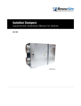
1.5 SENSOR LOCATIONS
OVERFLOW
SWITCH
MONITORS
CONDENSATE
LEVEL. ATTACHED
TO CONDENSATE
PAN (OPTIONAL)
EA STREAM
TEMPERATURE
SENSOR
(MOUNTED ON
AIR INLET CONE)
EA FAN AND SA
FAN CURRENT
SWITCHES
(MOUNTED ON
LOW-VOLTAGE
SIDE OF E-BOX
EA FAN
FLOW RATE
OA FILTER PRESSURE
RA FILTER PRESSURE
RA
TEMPERATURE
AND HUMIDITY
OA
TEMPERATURE
AND HUMIDITY
SA STREAM TEMPERATURE
SENSOR (MOUNTED ON
AIR INLET CONE WHEN THE
SA FAN IS POSITIONED
UPSTREAM OF THE COOLING
COIL. WHEN THE SA FAN IS
POSITIONED DOWNSTREAM
OF THE COOLING COIL, THE
SENSOR IS POSITIONED ON
THE CORE LEAVING SIDE OF
THE AIRSTREAM)
SA FAN FLOW RATE
COOLING COIL
LEAVING AIR
TEMPERATURE
SENSOR (ON
LEAVING SIDE OF
COOLING COIL WHEN
HGRH PRESENT)
CA TEMPERATURE
SENSOR (ON
LEAVING SIDE
OF THE HEATING
MODULE)
MAY BE LOCATED
IN DOWNSTREAM
DUCTWORK
NOTE: Not shown
here are the Smoke
Detector, CO2,
IAQ, Duct Pressure
Sensor, Room Temperature
and Humidity Sensor, and
Motion Detector. These
items are all accessories
and are field-installed.
FIGURE 1.5.0 SENSOR LOCATIONS IN DN-SERIES UNITS

1.800.627.4499
DN-Series Integrated Programmable ControlsDOAS
14
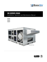
2.0 CONTROLLER OVERVIEW
The control utilizes the Carel c.pco (pronounced see-pee-ko) controller with the c.pcoe
expansion module.
C.pCO n° (03)
75.5°F
Time 12:33
date: 07.06.2017
12
3 4
5
7
8
9
10
11
124VAC Power
2Universal inputs/outputs
3Power for RUT remote display
4Remote display or
BMS connection
5Relay digital outputs
6+5V power supply
7FBUS connection to
expansion module
8Analog outputs
9Digital inputs
10 Ethernet port
11 Micro USB port
FIGURE 2.0.1 CONTROLLER EXTERNAL CONNECTIONS
6
CONTROLLER OVERVIEW
FIGURE 2.0.0 C.PCO CONTROLLER BUTTONS
4
3
2
1
1Up Button
2Enter Button
3Down Button
4Escape Button
5Program Button
6Alarm Button
6 5

151.800.627.4499
DN-Series Integrated Programmable Controls DOAS
The c.pCOe expansion module has multiple digital and analog inputs and outputs, serving as an
extension of the controller. The expansion board provides:
u Heating and Cooling Control
u Monitor Airflow Rates, Temperatures, and Pressures
FIGURE 2.0.2 EXPANSION MODULE DETAIL
NOTE: Expansion
module DIP switch-
es are factory set to
address 5, No Off-
set, 19.2K, and Modbus.
These settings should not
be changed.
NOTE: Dip switch
positions (Left to
Right) are always
set as follows:
Forward
Backward
Forward
Backward
Forward
Forward
Forward
Forward
CONTROLLER OVERVIEW
1
2
3
4
5
6
7
8
9
10
11
12
13
14
15 with oset
no oset
19.2 K
9.6 K
38.4 K
57.6 K
CAREL
Modbus
ON
OFF
Address Ext. ProtBaud
Address Ext Baud Prot
1 2
3
45
124VAC Power
2Universal inputs/outputs
3Relay digital outputs
4Serial connector to main controller
5Dip switches
FIGURE 2.0.3 OPTIONAL REMOTE USER TERMINAL (RUT) BUTTON LOCATIONS
ESCAPE BUTTON
ENTER BUTTON
UP BUTTON
DOWN BUTTON
PROGRAM BUTTON
ALARM BUTTON

1.800.627.4499
DN-Series Integrated Programmable ControlsDOAS
16
CONTROLLER OVERVIEW
2.1 CONTROLLER ACCESS METHODS
The controller has a built-in display that can be used to set up the system and view the status
of the system as well as address alarms. Two other options for accessing these are through the
remote RUT and through the embedded web pages. All three methods use similar keys for the
same purpose.
2.1.1 Using the Remote User Terminal (RUT)
The Remote User Terminal (RUT) allows you to plug into a controller and see the screens from
that controller. RUTs are connected to the controller by means of a 10' cable and then used as
hand-held devices. They can alternately be installed on a wall in some convenient location. The
push buttons on the face of the RUT have the same functions as the push buttons on
the controller.
FIGURE 2.1.0 OPTIONAL REMOTE USER TERMINAL (RUT)
NOTE: When an
alarm is first
detected, the Alarm
button will be flashing
and an audible alarm will
sound. After the alarm has
been viewed, the light will
remain on and the audible
alarm will stop.
Pressing the ALARM button displays any alarms that are currently active. There
may be multiple screens of alarms. Pressing and holding the Alarm button for three
seconds resets the alarms.
When a menu or menu item has been highlighted, press the “ENTER” hard button to
enter the highlighted selection. When a writable entry has been changed, press the
hard button to enter the new value and then press it again to confirm the change.
The ESC button is used to go one level back from the screen the user is currently on.
If the user is finished setting variables in a sub-menu, the ESC button takes them
back to the previous menu. If the user is editing a variable and decides to not make
a change, the ESC button takes them back to the top of that screen. Pressing the
ESC button from the Main Menu takes the user back to the Main Status screen.
Pressing the PRG (program) button accesses the Service Menu or Login screen from
any location in the user interface screens. The options that are available dynamically
change depending on the configuration of the unit and the options installed on
the unit.
When on a screen with the cursor in the upper left-hand corner,the UP or DOWN hard
buttons move the user from one screen to the next. While editing a variable, the UP
or DOWN hard buttons allow the user to set the desired value of the variable. When
viewing a view only variable, the UP or DOWN hard buttons scroll through the values
available to the user.

171.800.627.4499
DN-Series Integrated Programmable Controls DOAS
CONTROLLER OVERVIEW
The RUT (optional accessory, field-installed) plugs into the controller by means of a six wire
cable with RJ12 jacks on each end. The six-wire cable is inserted in the RJ12 jack on the back
of the RUT and the other end of the cable is inserted into the RJ12 adapter, found in the low
voltage electrical compartment. The controller uses a pre-conFigured cable that plugs into the
J3 jack on the controller and the other end is plugged into the RJ12 adapter. The cable looks
similar to a standard phone cable but has a different pin out. The cable from the controller to
the low voltage electrical box is factory-installed.
FIGURE 2.1.1 CONNECTING A RUT
BACK OF RUT
LOW VOLTAGE
ELECTRICAL
COMPARTMENT
NOTE: Common
telephone wiring
is 4 conductor and
uses RJ11 termi-
nals. It is different from
the six-wire cable with
RJ12 terminals needed for
this accessory.
NOTE: If the con-
troller was ordered
for use with a
serial BMS and an
RUT is also desired,
contact the factory for
further information.
2.1.2 Connecting Using Internal Web Pages
The controller has embedded web pages and when they are accessed, an interactive screen
appears that allows the user to move through all the controller menus. The IP address of the
controller is factory-set at 10.10.1.2. The subnet address (needed for setting up a LAN) is set at
255.255.255.0. These can be changed in the General Settings menu.
In order to connect to the controller with your pc you will need:
u An ethernet cable between the PC and the controller
u The PC connection must be on the same subnet as the controller. For example, if using the
defaults, you would set the IP address of the PC connection to 10.10.1.xx where xx is not
equal to 2, and the subnet to 255.255.255.0. (See directions for setting the PC IP address if
you are not familiar with this.)
NOTE: The controller
will only support
private IP addresses
which start with
192, 172, or 10.
u Using a browser such as Chrome, put the controller IP address into the address bar.
NOTE: For direct
connection from
RUT to J3 Terminal,
use the following
wiring:
Green & Black = +Vterm
Brown & Blue = GND
Red = Negative (-)
White = Positive (+)

1.800.627.4499
DN-Series Integrated Programmable ControlsDOAS
18
You should see this web page. To get to the menu screens, click on RUT on the Menu Bar.
2.1.3 Setting the PC IP Address
For those that are not familiar with changing their PC adapter settings, go into Network Setting
in the Control Panel and Change Adapter Settings.
Choose the adapter you are using to connect to the controller.
CONTROLLER OVERVIEW

191.800.627.4499
DN-Series Integrated Programmable Controls DOAS
Select Internet Protocol 4 and click on Properties.
Enter the IP address you want to use. It should not be identical to the controller IP address. The
last octet of the IP address should be different. Click OK.
2.1.4 Using the Multikey Function of the Web Pages
When you want to press multiple keys or press a key longer for a function you can use the keys
below the Menu Screens to do this.
Two common uses are:
u Set the two keys to Alarm and Alarm and press Simulate long press to acknowledge alarms.
u Set the two keys to Alarm and Enter and press Simulate long press to get to system menus.
CONTROLLER OVERVIEW
NOTE: When you are
finished viewing the
controller on
your computer,
remember to restore the
original settings.
2.2 CONTROLLER MENU STRUCTURE
Any screen will have the name of the menu to which it belongs on the top line of the screen.
2.2.1 User Menu Structure
The user menu can be reached but pressing the ESC (back) button. The menus contain the
following areas:
u Unit Status—Contains the status values of the sensors, fans, and heating and cooling,
if applicable
u Control Settings—Contains the control settings for the fans and heating and cooling,
if applicable
u General Settings—Contains the clock settings, Unit of Measures, IP Address, BMS settings,
and the scheduler
u Alarm Settings—Contains the alarm settings
u Unit On/Off—Allows the user to turn the unit on and off via the keypad

1.800.627.4499
DN-Series Integrated Programmable ControlsDOAS
20
2.2.2 Password Protected Menu Structure
The password protected menu can be reached but pressing the PROG button and entering the
password. The menus contain the following areas:
u Back Up and Restore—Contains the screens to back up your settings or return to
factory defaults
u Unit Configuration—Main Unit Configuration Settings that determine which screens show up
in other areas
u I/O Configuration—Secondary configuration settings for functions
u I/O Calibration—Allows sensors to be adjusted for accuracy
u Sensor Overrides—Allows a sensor value to be temporarily overwritten for testing
u Test End Devices—Allows outputs to be manually manipulated for troubleshooting
u Advanced Service—Advanced Service Information and Settings
2.2.3 Password Entry
To access the password protected service screens, press the program (bullseye) button to get
to the screen and enter the user password “1000.”
GENERAL FLOW
3.0 GENERAL FLOW FOR SETUP AND RUNNING UNIT
Depending upon features selected for the unit, the general flow for setup and running the unit is
as follows:
GENERAL SETTING:
CLOCK, UNIT OF MEASURE, IP
ADDRESS, SCHEDULE
UNIT CONFIGURATION:
ENABLE HEAT AND/OR COOL, FAN
TYPE, DEFROST...
I/O CONFIGURATION:
ENABLE EXTRA SENSOR AND
SPECIAL FEATURES
FAN CONFIGURATION:
SET SUPPLY AND EXHAUST FAN
CONTROL TYPES
START UNIT:
PROVE FAN RUNNING
TEST HEATING:
CHOOSE HEAT TYPE AND TEST
TEST COOLING:
CHOOSE COOLING TYPE AND TEST
TEST DEHUMIDIFICATION:
CHOOSE TYPE AND TEST
TEST ECONOMIZER:
CHOOSE TYPE AND TEST
TEST FROST CONTROL:
SET CONTROL AND TEST
TEST RECIRCULATION:
SET CONTROL AND TEST
TEST SINGLE FAN MODE:
IF DESIRED
BMS INTEGRATION:
CHOOSE TYPE AND TEST
/