
Tranquility
OA
(TO) Series
Commercial Vertical
Dedicated Outdoor Air
Packaged Water-Source
Heat Pumps
Installation, Operation
& Maintenance
97B0052N01
Revised: 31 January, 2013
Table of Contents
Model Nomenclature 3
General Information 4
Unit Connections and Service Clearances 4-15 Tons 7
Unit Connections and Service Clearances 20-30 Tons 8
Vertical Dimensional Data Model 04 & 05 9
Vertical Dimensional Model 08 & 10 10
Vertical Dimensional Data Model 15 11
Vertical Dimensional Data - Model 20-30 12
Vertical Dimensional Model 04 & 05 13
Vertical With Damper Box Dimensional Data -
Model 20 - 30 14
Vertical Dimensional - Model 08 & 10 15
Vertical Dimensional - Model 15 16
TO VF/VD Physical Data Table 17
Vertical Installation 18
Duct System Installation 19
Piping Installation 22
Water Quality Standards 23
Electrical Wiring - Line Voltage 24
Electrical Wiring - Low Voltage 25
Unit Starting & Operating Conditions 27
System Operation Modes 29
Service and Maintenance 31
Troubleshooting 33
Appendix 34
Service Bulletin 35
Start-Up Report 37
Warranty 41
Revision History 44

CLIMATEMASTER WATER-SOURCE HEAT PUMPS
Vertical DOAS
Rev.: 01/31/13
2
ClimateMaster Water-Source Heat Pumps
This Page Intentionally Left Blank

THE SMART SOLUTION FOR ENERGY EFFICIENCY
Vertical DOAS
Rev.: 01/31/13
3
climatemaster.com
Model Nomenclature
A
B
C
D
E
F
G
H
0.5
1
1.5
2
5
7.5
-
-
-
-
-
-
-
MOTOR HPOPTION
10
-
J
K
L
M
N
P
15
20
25
30
0.5
-
-
-
-
X
1
X
Q
R
1.5
X
2
X
w/ VFD
3
S
3
X
T
5
X
U
7.5
X
V
10
X
W
15
X
1
20
X
2
25
X
3
30
X
-
N
A
B
E
F
OPTION
-
C
D
STANDARD
FILTER
-
G
H
NONE (NO WHEEL)
REAR RETURN
BOTTOM RETURN
STANDARD FILTER
WITH PRE-FILTER
MERV 13
FILTER
MERV 13
WITH PRE-FILTER
F
T
B
A
G
H
OPTION
C
D
E
STANDARD
FILTER
J
K
L
TOP
REAR DISCHARGE
STANDARD FILTER
WITH PRE-FILTER
MERV 13
FILTER
MERV 13
WITH PRE-FILTER
A
B
C
D
E
F
G
H
0.5
1
1.5
2
5
7.5
-
-
-
-
-
-
-
MOTOR HPOPTION
10
-
J
K
L
M
N
P
15
20
25
30
0.5
-
-
-
-
X
1
X
Q
R
1.5
X
2
X
w/ VFD
3
S
3
X
T
5
X
U
7.5
X
V
10
X
W
15
X
1
20
X
2
25
X
3
30
X
OPTION
B
C
K
L
M
N
P
R
X
X
-
-
X
-
X
-
-
X
X
-
-
X
-
X
-
X
-
X
NON-COATED
COIL
OPTION
-
X
-
-
X
-
X
-
X
-
X
COATED
COIL
SIDE WATER
CONNECTION
BOTTOM WATER
CONNECTION
LEFT HAND
ACCESS
X
-
-
-
-
X
X
X
X
X
X
X
X
-
-
-
-
RIGHT HAND
ACCESS
G
H
F
N
A
B
C
D
X
-
-
-
X
X
-
-
X
-
-
-
-
-
-
X
-
-
-
-
208-230/60/1OPTION
-
X
-
-
-
-
X
-
-
-
-
J
K
L
M
Y
P
-
-
-
-
-
X
X
-
-
-
-
-
X
X
X
-
-
-
-
-
-
-
-
X
R
W
-
-
-
-
-
-
X
X
208-230/60/3 460/60/3 575/60/3 NON- FUSED DISC.
GFI
X
-
-
-
-
X
-
X
X
-
X
X
-
X
X
-
X
-
-
-
-
-
X
X
-
X
X
-
X
X
-
X
X
TO C30 EF 3 A B N T A
1 2
3 4
5 6
7
8
9101112131415
MODEL TYPE
HD = HORIZONTAL NO WHEEL
CONFIGURATION
HW = HORIZONTAL w/ WHEEL
UNIT SIZE
04 - (VD, VF)
05
08
10
15
20
30
25
36
40
SUPPLY MOTOR HP
HEAT EXCHANGER OPTIONS
EXHAUST MOTOR HP
46
TO = TRANQUILITY
®
(HFC-410A) OUTSIDE AIR
RD = ROOFTOP (OUTDOOR) NO WHEEL
RW = ROOFTOP ( OUTDOOR ) w/ WHEEL
VD = VERTCAL w/DAMPER BOX
V F
50
56
60
REVISION LEVEL
VOLTAGE
CONTROLS / MISC OPTIONS
E = LAT (STANDARD)
SUPPLY AIR CONFIGURATION
VF = VERTICAL w/ FILTER BOX (STANDARD)
J = ZONE RESET
03
H = LAT (STANDARD), VFD FOR WHEEL
M = ZONE RESET, VFD FOR WHEEL
C = CAREL
TOP VIEW
LH
RH
REAR
O/A >
(FRONT)
R = NIGHT SETBACK (HB, RB, & VD ONLY)
S = R + VFD FOR WHEEL
T = CO2
U = CO2, VFD FOR WHEEL
02
HB = HORIZONTAL w/WHEEL AND BYPASS DAMPER
RB = ROOFTOP w/WHEEL AND BYPASS DAMPER
RETURN AIR CONFIGURATION
BOTTOM DISCHARGE
COMMUNICATION OPTIONS
COMMUNICATION CONFIGURATION
1
2
CONTROLLER WITH NO BMS
CONTROLLER WITH BACnet Enet
3
CONTROLLER WITH BACnet MS/TP
4
CONTROLLER WITH LON
5
CONTROLLER WITH MODBUS
{
ALL
CONFIGURATIONS
{
HD / RD
CONFIGURATION
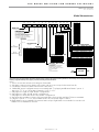
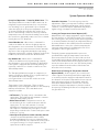
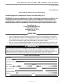
NOTE: A dedicated 115 VAC, 15 Amp circuit (by others) is required on all DOAS units for operation of the factory installed evaporator heat tape(s). Failure to connect heat tape(s) to a
proper power supply may lead to freezing of the water in the heat exchanger. Failure of, and/or damage caused by the failure of a heat exchanger due to freezing will be exempt from
warranty coverage if the heat tapes are not properly connected and working at the time of the failure.
Notes:
1. Service access side referenced looking into O/A intake.
2. Side water connections are always on the same side as access except for horizontal size 20.
3. Condensate connection same side as water connections.
4. “HW & RW” model confi gurations are not available with “Top Supply with Bottom Return” option. if
digit 14 is “T, F, C, or J” then digit 13 must be “A, E, C, or G”.
5. Only applies to “RW” & “HW” model confi gurations.
6. Only applies to “RB” & “HB” model confi gurations.
7. Only applies to horizontal and rooftop model confi gurations.
8. Vertical models use Merv 11 fi lters only; horizontal and rooftop models use Merv 7 fi lters as standard.
9. If digit 9 is option “T” or “U”, then vfd will need to be selected in digits 11 and 15.
10. Right hand access is standard for horizontal and rooftops. Right hand is not available for verticals. Left
hand access is standard for verticals.

CLIMATEMASTER WATER-SOURCE HEAT PUMPS
Vertical DOAS
Rev.: 01/31/13
4
ClimateMaster Water-Source Heat Pumps
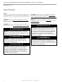
General Information
WARNING! The unit label will indicate which refrigerant is
provided. The EarthPure® Application and Service Manual
should be read and understood before attempting to service
refrigerant circuits with HFC-410A.
WARNING! To avoid the release of refrigerant into the
atmosphere, the refrigerant circuit of this unit must be
serviced only by technicians who meet local, state, and
federal profi ciency requirements.
CAUTION! To avoid equipment damage, DO NOT use
these units as a source of heating or cooling during the
construction process. The mechanical components and fi lters
will quickly become clogged with construction dirt and debris,
which may cause system damage.
WARNING!
WARNING!
WARNING!
CAUTION!
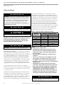
Safety
Warnings, cautions, and notices appear throughout this
manual. Read these items carefully before attempting any
installation, service, or troubleshooting of the equipment.
DANGER: Indicates an immediate hazardous situation,
which if not avoided will result in death or serious injury.
DANGER labels on unit access panels must be observed.
WARNING: Indicates a potentially hazardous situation,
which if not avoided could result in death or serious injury.
CAUTION: Indicates a potentially hazardous situation or
an unsafe practice, which if not avoided could result in
minor or moderate injury or product or property damage.
NOTICE: Notifi cation of installation, operation, or
maintenance information, which is important, but which is
not hazard-related.
WARNING! All refrigerant discharged from this unit must
be recovered WITHOUT EXCEPTION. Technicians must
follow industry accepted guidelines and all local, state, and
federal statutes for the recovery and disposal of refrigerants.
If a compressor is removed from this unit, refrigerant circuit
oil will remain in the compressor. To avoid leakage of
compressor oil, refrigerant lines of the compressor must be
sealed after it is removed.
WARNING!
WARNING! The installation of water-source heat pumps and
all associated components, parts, and accessories which
make up the installation shall be in accordance with the
regulations of ALL authorities having jurisdiction and MUST
conform to all applicable codes. It is the responsibility of
the installing contractor to determine and comply with ALL
applicable codes and regulations.

THE SMART SOLUTION FOR ENERGY EFFICIENCY
Vertical DOAS
Rev.: 01/31/13
5
climatemaster.com
Inspection -
ClimateMaster DOAS units are not designed
to support the weight of a person on all portions of the
unit roof. Personnel should avoid stepping on the top of
the unit. However, if it is necessary to stand on the roof,
stay within 18” of the cabinet perimeter.
ClimateMaster inspects and tests each DOAS unit before
it leaves the factory so that you receive a quality piece
of equipment. However, the DOAS unit may have been
damaged in transit. Check the equipment thoroughly for
both visible and concealed damage before you sign the
receiving papers. Pay particular attention to the roof of the
unit on outdoor units. Document any damage in writing
on the carrier’s bill of lading to ensure that damage claims
are handled promptly. If the unit has been damaged,
obtain a claim form from the carrier. Promptly fi ll out and
return the form, and notify ClimateMaster of any damage.
DAMAGE CLAIMS OR SHORTAGES MUST BE FILED
WITH THE FREIGHT CARRIER WITHIN 5 WORKING DAYS
OF RECEIPT OF EQUIPMENT.
Storage -
Equipment should be stored in its original
packaging in a clean, dry area. Store units in an upright
position at all times. Do not stack units or any other
equipment on any DOAS unit.
Unit Protection -
Cover units on the job site with either
the original packaging or an equivalent protective
covering. Cap the open ends of pipes stored on the
job site. In areas where painting, plastering, and/or
spraying has not been completed, all due precautions
must be taken to avoid physical damage to the units and
contamination by foreign material. Physical damage and
contamination may prevent proper start-up and may result
in costly equipment clean-up.
Examine all pipes, fi ttings, and valves before installing
any of the system components. Remove any dirt or debris
found in or on these components.
Pre-Installation -
ClimateMaster 100% outdoor air DOAS
units designed for indoor installations are confi gured
to allow single-side access to regularly maintained
components. This means you can make your service
connections and perform routine maintenance even when
you must install one side of the DOAS unit against a wall
or other restriction. The “service side” is determined when
the order is placed at the factory. Note that the service
side cannot be changed in the fi eld. It is recommended
that clearance be provided on all sides to allow for ease
of servicability in the event large components require
replacement.
Allow a minimum of 36 inches of clearance around
the service side of the DOAS unit for piping, electrical
connections, and service access. Install the unit on a
sturdy, level mounting base or platform that will prevent
vibration and sound transmission. Never install the DOAS
unit on a wooden platform. Do not install the unit near
occupied rooms such as offi ces or guestrooms. Do not
attempt to conserve installation space by fabricating
restrictive ductwork with abrupt bends. You may reduce
the operating effi ciency and the moisture removal capacity
of the DOAS unit. See duct system installation section for
detailed duct installation instructions.
NOTICE! -
YOU MUST NOT INSTALL AN INDOOR-
RATED DOAS UNIT IN AN OUTDOOR OR A WET
ENVIRONMENT. If you must install the DOAS unit outside
you must use an outdoor-rated DOAS unit. ClimateMaster
seals and weatherproofs outdoor DOAS units to help
prevent water infi ltration. You can determine whether your
DOAS unit is outdoor-rated by inspecting the unit rating
plate (see Section 4.1 for details).
Prepare units for installation as follows:
1. Compare the electrical data on the unit nameplate
with ordering and shipping information to verify that
the correct unit has been shipped.
2. Keep the cabinet covered with the original packaging
until installation is complete and all plastering,
painting, etc. is fi nished.
3. Verify refrigerant tubing is free of kinks or dents and
that it does not touch other unit components.
4. Inspect all electrical connections. Connections must
be clean and tight at the terminals.
5. Some accessory items such as sensor(s), interface
module, etc may be shipped packed in the
compressor compartment.

CLIMATEMASTER WATER-SOURCE HEAT PUMPS
Vertical DOAS
Rev.: 01/31/13
6
ClimateMaster Water-Source Heat Pumps
CAUTION! DO NOT store or install units in corrosive
environments or in locations subject to temperature or
humidity extremes (e.g., attics, garages, rooftops, etc.).
Corrosive conditions and high temperature or humidity can
signifi cantly reduce performance, reliability, and service life.
Always move and store units in an upright position. Tilting
units on their sides may cause equipment damage.
CAUTION!
CAUTION!
CAUTION!
CAUTION! CUT HAZARD - Failure to follow this caution may
result in personal injury. Sheet metal parts may have sharp
edges or burrs. Use care and wear appropriate protective
clothing, safety glasses and gloves when handling parts and
servicing heat pumps.
Rigging -
ClimateMaster DOAS units are solidly built and
can be very heavy. Avoid personal injury and damaged
equipment by planning the installation carefully. Use
moving equipment whenever possible.
Moving the DOAS Unit -
Use hand trucks, equipment
dollies or pipe rollers to move the DOAS Unit into place.
Use caution so that the DOAS Unit does not tip over.
CAUTION!
CAUTION! Do not tip the DOAS unit on its side. Avoid
dropping the unit down stairways or subjecting it to severe
mechanical shock. You may seriously damage the unit!
Failure to observe these instructions may lead to equipment
damage, personal injury, or death.
CAUTION! All three phase scroll compressors must have
direction of rotation verifi ed at start-up. Verifi cation is
achieved by checking compressor Amp draw. Amp draw
will be substantially lower compared to nameplate values.
Additionally, reverse rotation results in an elevated sound
level compared to correct rotation. Reverse rotation will result
in compressor internal overload trip within several minutes.
Verify compressor type before proceeding.

THE SMART SOLUTION FOR ENERGY EFFICIENCY
Vertical DOAS
Rev.: 01/31/13
7
climatemaster.com
Unit Connections and Service Clearances 4-15 Tons
Notes:
1. Primary Side Access: 4 & 5 HP Units require 3’ - 0” clearance due to electrical panel. 8, 10, & 15 HP Units
require a minimum of 2’ - 0” for service clearance, but 3’-0” is preferred.
2. Left Service Side Access: Requires 3’-0” access clearance for service and fi lter access.
3. If water piping or condensate drain is provided on the right side of the unit opposite the left hand shown, provide
adequate space for fi eld connection and any piping specialties.
TOV 4-15 Tons
Utility Location
Electrical Access See Drawing
Service Access Primary Side & Left Side
Filter Access Left Side
Water Cooled
Piping Connection(s)
Left (See Drawing)
Condensate Drain Left (See Drawing)

CLIMATEMASTER WATER-SOURCE HEAT PUMPS
Vertical DOAS
Rev.: 01/31/13
8
ClimateMaster Water-Source Heat Pumps
Unit Connections and Service Clearances 20-30 Tons
TOV 20-30 Tons
Notes:
1. Primary Service Side Access require 3’ - 0” clearance due to electrical panel.
2. Left Service Side Access: Requires 3’-0” access clearance for service and fi lter access. The unit shown
above is standard Left Hand Access. A unit that is Right Hand Access will mirror the left hand access
shown above.
Utility Location
Electrical Access Primary Service Side
Service Access Primary Side & Left Side
Filter Access Left Side
Water Cooled
Piping Connection(s)
Left (See Drawing)
Condensate Drain Left Side

THE SMART SOLUTION FOR ENERGY EFFICIENCY
Vertical DOAS
Rev.: 01/31/13
9
climatemaster.com
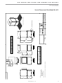
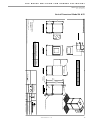
Vertical Dimensional Data Model 04 & 05
3.00*
DISCHARGE VIEW
Vertical 4-5 Ton Cabinet
Drawing Number
Page Title
Description
4-5 TON CABINET
Vertical Discharge
1/3
.030
1/8"
Angles
All outside corners 0.125" fillet
Part weight
Third Angle Projection
Unless Otherwise Specified
1
Date Released
Drawn
Scale
Sheet
Rev.
9/12/2002SK
51:20
Tolerance Unless
Otherwise Specifed
X.X
.125
X.XX
.060
X.XXX
All Dimensions in Inches
All Angles 90
ALL DIMENSIONS ARE IN INCHES
TOLERANCE
GENERAL ARRANGEMENT
BACK SIDE
(SERVICE ACCESS) VIEW
24.96
WIDTH**32.09
OVERALL WIDTH38.95
24.82
3' SERVICE CLEARANCE REQUIRED
NOTES:
FRONT OF UNIT LOOKING 1.
INTO OUTDOOR AIR INTAKE,
WATER CONNECTIONS
LEFT SIDE ONLY.
(SERVICE ACCESS) VIEW
FRONT SIDE
(O/A INTAKE) VIEW
LEFT SIDE
* APPROXIMATE DIMENSION
** ADD APPROXIMATELY 0.5 IN. FOR EXTERIOR PANEL FASTENERS
36.19
22.98
LOCATION
ELECTRICAL
ENCLOSURE
WATER CONNECTIONS AND
CONDENSATE STUB LOCATION
OVERALL
HEIGHT
HEIGHT
CABINET
58.42
60.11
34.15 LENGTH**
RIGHT SIDE VIEW
(NO ACCESS)
28.48
W X
Z
Y
3.44
1" I.D.1 3/8" O.D.1 3/8" O.D.
OUTLET
WATER COOLED AND HEAT PUMP
CONDENSER CONNECTIONS
CONDENSATE
DRAIN
CONNECTION
INLET OUTLET
BLOWER MODEL W X Y Z
110-4 13.60" 6.87" 12.50" 7.13"
110-10 10.47" 13.12" 12.50" 7.00"
Geothermal Heat Pump Systems

CLIMATEMASTER WATER-SOURCE HEAT PUMPS
Vertical DOAS
Rev.: 01/31/13
10
ClimateMaster Water-Source Heat Pumps
3.00*
Drawing Number
Page Title
Description
8-10 TON CABINET
Tolerance Unless
Otherwise Specifed
X.X
.125
X.XX
.060
X.XXX
.030
Angles
1
Date Released
Drawn
Scale
Sheet
Rev.
9/12/2002SK
5
1:24
All Dimensions in Inches
All Angles 90
All outside corners 0.125" fillet
Unless Otherwise Specified
Third Angle Projection
Part weight
ALL DIMENSIONS ARE IN INCHES
TOLERANCE
1/8"
2/3
Vertical Discharge
Vertical 8-10 Ton Cabinet
GENERAL ARRANGEMENT
3' SERVICE CLEARANCE REQUIRED
NOTES:
FRONT OF UNIT LOOKING 1.
INTO OUTDOOR AIR INTAKE,
WATER CONNECTIONS
LEFT SIDE ONLY.
ELECTRICAL
ENCLOSURE
LOCATION
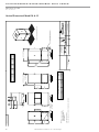
51.19
27.98
* APPROXIMATE DIMENSION
** ADD APPROXIMATELY 0.5 IN. FOR EXTERIOR PANEL FASTENERS
DISCHARGE VIEW
W
X
Z
Y
38.944.47
RIGHT SIDE VIEW
(NO ACCESS)
35.09 WIDTH**
41.95 OVERALL WIDTH
24.82
29.96
FRONT SIDE
(O/A INTAKE) VIEW
LEFT SIDE
(SERVICE ACCESS) VIEW
WATER COOLED AND HEAT PUMP
CONDENSER CONNECTIONS
CONDENSATE
DRAIN
CONNECTION
INLET OUTLET OUTLET
1 3/8" O.D. 1 3/8" O.D. 1" I.D.
BLOWER MODEL W X Y Z
110-4 19.60" 6.87" 12.50" 8.88"
110-10 16.47" 13.12" 12.50" 8.88"
BACK SIDE
(SERVICE ACCESS) VIEW
WATER CONNECTIONS AND
CONDENSATE STUB LOCATION
78.42
CABINET
HEIGHT
80.11
OVERALL
HEIGHT
46.15 LENGTH**
Geothermal Heat Pump Systems
Vertical Dimensional Model 08 & 10

THE SMART SOLUTION FOR ENERGY EFFICIENCY
Vertical DOAS
Rev.: 01/31/13
11
climatemaster.com
3.00*
RIGHT SIDE VIEW
(NO ACCESS)
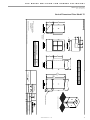
41.95 OVERALL WIDTH
35.09 WIDTH**
39.50
29.93
WATER COOLED AND HEAT PUMP
CONDENSER CONNECTIONS
CONDENSATE
DRAIN
CONNECTION
INLET OUTLET OUTLET
1 5/8" O.D. 1 5/8" O.D. 1" I.D.
BLOWER MODEL W X Y Z
110-10 16.47" 13.12" 12.50" 8.88"
120-12 15.22" 15.62" 13.53" 8.38"
3' SERVICE CLEARANCE REQUIRED
NOTES:
FRONT OF UNIT LOOKING 1.
INTO OUTDOOR AIR INTAKE,
WATER CONNECTIONS
LEFT SIDE ONLY.
FRONT SIDE
(O/A INTAKE) VIEW
ELECTRICAL
ENCLOSURE
LOCATION
LEFT SIDE
(SERVICE ACCESS) VIEW
51.19
27.98
DISCHARGE VIEW
* APPROXIMATE DIMENSION
** ADD APPROXIMATELY 0.5 IN. FOR EXTERIOR PANEL FASTENERS
W
X
Z
Y
38.944.47
BACK SIDE
(SERVICE ACCESS) VIEW
WATER CONNECTIONS AND
CONDENSATE STUB LOCATION
78.42
CABINET
HEIGHT
80.11
OVERALL
HEIGHT
46.15 LENGTH**
Drawing Number
Page Title
Description
15 TON CABINET
Tolerance Unless
Otherwise Specifed
X.X
.125
X.XX
.060
X.XXX
.030
Angles
1
Date Released
Drawn
Scale
Sheet
Rev.
9/12/2002SK
5
1:24
All Dimensions in Inches
All Angles 90
All outside corners 0.125" fillet
Unless Otherwise Specified
Third Angle Projection
Part weight
ALL DIMENSIONS ARE IN INCHES
TOLERANCE
1/8"
3/3
Vertical Discharge
Vertical 15 Ton Cabinet
GENERAL ARRANGEMENT
Geothermal Heat Pump Systems
Vertical Dimensional Data Model 15

CLIMATEMASTER WATER-SOURCE HEAT PUMPS
Vertical DOAS
Rev.: 01/31/13
12
ClimateMaster Water-Source Heat Pumps
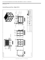
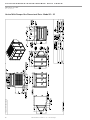
Vertical Dimensional Data - Model 20-30
Drawing Number
Page Title
Description
Vertical 20-30 Ton Cabinet
GENERAL ASSEMBLY
Tolerance Unless
Otherwise Specifed
X.X ± .125
X.XX ± .060
X.XXX ± .030
Angles ± 1°
Date Released
Drawn
Scale
Sheet
Rev.
4/23/04
SK
1 / 1
0
1:32
All Dimensions in Inches
All Angles 90°
All Outside Corners 0.094" Radius
Unless Otherwise Specified
Third Angle Projection
Material
Finish
Vertical 20-30 Ton LH Access
Part Based On
Part weight
77.250 OVERALL LENGTH
FRONT O/A INTAKE VIEW
RIGHT SIDE VIEW LEFT SIDE SERVICE ACCESS VIEW
TOP DISCHARGE VIEW
BACK PRIMARY SERVICE ACCESS VIEW
ELECTRICAL
COMPARTMENT
11.000*
7.000*
11.000*
7.000*
60.000
DISCHARGE OPENING
10.840
40.000
8.625
LEFT-HAND ACCESS
ELECTRICAL ENTRY
RIGHT-HAND ACCESS
ELECTRICAL ENTRY
5.000*
2.625*
54.000
CABINET WIDTH
61.519
OVERALL WIDTH
69.971
OVERALL
HEIGHT
STD. CONDENSATE
DRAIN LOCATION
5.000*
11.000*
7.565
* APPROXIMATE DIMENSION
OPTIONAL CONDENSATE
DRAIN LOCATION
23.500 *
23.500*
12.000*
TYP
6.000* TYP
10.000*
TYP
8.242
43.516
INTAKE
OPENING
3.341
70.568
INTAKE OPENING
LEFT-HAND
WATER CONNECTIONS
RIGHT-HAND
WATER CONNECTIONS
(3) 870-041
20x24x4 AIR FILTERS
(3) 870-012
24x24x4 AIR FILTERS
Geothermal Heat Pump Systems

THE SMART SOLUTION FOR ENERGY EFFICIENCY
Vertical DOAS
Rev.: 01/31/13
13
climatemaster.com
Third Angle Projection
3.00*
Vertical Discharge w/ OA Mixing Box
Drawing Number
Page Title
Description
4-5 TON CABINET1/3
1/8"
.030
Angles
All outside corners 0.125" fillet
Part weight
Unless Otherwise Specified
1
Date Released
Drawn
Scale
Sheet
Rev.
2/17/2003SK
5
1:20
Tolerance Unless
Otherwise Specifed
X.X
.125
X.XX
.060
X.XXX
All Dimensions in Inches
All Angles 90
ALL DIMENSIONS ARE IN INCHES
TOLERANCE
GENERAL ARRANGEMENT
BACK SIDE
(SERVICE ACCESS) VIEW
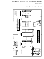
32.09 UNIT WIDTH**
54.21 OVERALL WIDTH**
3' SERVICE CLEARANCE REQUIRED
RIGHT SIDE VIEW
(NO ACCESS)
Z
W X
Y
FRONT SIDE
(O/A INTAKE) VIEW
(SERVICE ACCESS) VIEW
LEFT SIDE
* APPROXIMATE DIMENSION
** ADD APPROXIMATELY 0.5 IN. FOR EXTERIOR PANEL FASTENERS
36.19
22.98
Z
110-4 13.60" 6.87" 12.50" 7.13"
110-10 10.47" 13.12" 12.50" 7.00"
BLOWER MODEL W X Y
WATER COOLED AND HEAT PUMP
CONDENSER CONNECTIONS
CONDENSATE
DRAIN
CONNECTION
INLET OUTLET OUTLET
1 3/8" O.D. 1 3/8" O.D. 1" I.D.
NOTES:
FRONT OF UNIT LOOKING 1.
INTO OUTDOOR AIR INTAKE,
WATER CONNECTIONS
LEFT SIDE ONLY.
LOCATION
ELECTRICAL
ENCLOSURE
WATER CONNECTIONS AND
CONDENSATE STUB LOCATION
OVERALL
HEIGHT
HEIGHT
CABINET
58.42
60.11
34.15 LENGTH**
DISCHARGE VIEW
Geothermal Heat Pump Systems
Vertical 4-5 Ton & Mixing Box
Vertical Dimensional Model 04 & 05

CLIMATEMASTER WATER-SOURCE HEAT PUMPS
Vertical DOAS
Rev.: 01/31/13
14
ClimateMaster Water-Source Heat Pumps
Vertical With Damper Box Dimensional Data - Model 20 - 30
Vertical 20-30 Ton & Mixing Box

THE SMART SOLUTION FOR ENERGY EFFICIENCY
Vertical DOAS
Rev.: 01/31/13
15
climatemaster.com
3.00*
Drawing Number
Page Title
Description
8-10 TON CABINET
Tolerance Unless
Otherwise Specifed
X.X
.125
X.XX
.060
X.XXX
.030
Angles
1
Date Released
Drawn
Scale
Sheet
Rev.
2/17/2003SK
5
1:24
All Dimensions in Inches
All Angles 90
All outside corners 0.125" fillet
Unless Otherwise Specified
Third Angle Projection
Part weight
ALL DIMENSIONS ARE IN INCHES
TOLERANCE
1/8"
2/3
Vertical Discharge w/ OA Mixing Box
GENERAL ARRANGEMENT
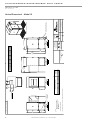
BLOWER MODEL W X Y Z
110-4 19.60" 6.87" 12.50" 8.88"
110-10 16.47" 13.12" 12.50" 8.88"
WATER COOLED AND HEAT PUMP
CONDENSER CONNECTIONS
CONDENSATE
DRAIN
CONNECTION
INLET OUTLET OUTLET
1 3/8" O.D. 1 3/8" O.D. 1" I.D.
NOTES:
FRONT OF UNIT LOOKING 1.
INTO OUTDOOR AIR INTAKE,
WATER CONNECTIONS
LEFT SIDE ONLY.
35.09 UNIT WIDTH**
22.12
MIXING
BOX
57.21 OVERALL WIDTH**
ELECTRICAL
ENCLOSURE
LOCATION
51.19
27.98
3' SERVICE CLEARANCE REQUIRED
RIGHT SIDE VIEW
(NO ACCESS)
FRONT SIDE
(O/A INTAKE) VIEW
LEFT SIDE
(SERVICE ACCESS) VIEW
* APPROXIMATE DIMENSION
** ADD APPROXIMATELY 0.5 IN. FOR EXTERIOR PANEL FASTENERS
BACK SIDE
(SERVICE ACCESS) VIEW
DISCHARGE VIEW
W X
Y
Z
WATER CONNECTIONS AND
CONDENSATE STUB LOCATION
78.42
CABINET
HEIGHT
80.11
OVERALL
HEIGHT
46.15 LENGTH**
Geothermal Heat Pump Systems
Vertical 8-10 Ton & Mixing Box
Vertical Dimensional - Model 08 & 10

CLIMATEMASTER WATER-SOURCE HEAT PUMPS
Vertical DOAS
Rev.: 01/31/13
16
ClimateMaster Water-Source Heat Pumps
3.00*
WATER COOLED AND HEAT PUMP
CONDENSER CONNECTIONS
CONDENSATE
DRAIN
CONNECTION
INLET OUTLET OUTLET
1 5/8" O.D. 1 5/8" O.D. 1" I.D.
BLOWER MODEL W X Y Z
110-10 16.47" 13.12" 12.50" 8.88"
120-12 15.22" 15.62" 13.53" 8.38"
NOTES:
FRONT OF UNIT LOOKING 1.
INTO OUTDOOR AIR INTAKE,
WATER CONNECTIONS
LEFT SIDE ONLY.
FRONT SIDE
(O/A INTAKE) VIEW
3' SERVICE CLEARANCE REQUIRED
ELECTRICAL
ENCLOSURE
LOCATION
LEFT SIDE
(SERVICE ACCESS) VIEW
51.19
27.98
DISCHARGE VIEW
* APPROXIMATE DIMENSION
** ADD APPROXIMATELY 0.5 IN. FOR EXTERIOR PANEL FASTENERS
W
X
Y
Drawing Number
Page Title
Description
15 TON CABINET
Tolerance Unless
Otherwise Specifed
X.X
.125
X.XX
.060
X.XXX
.030
Angles
1
Date Released
Drawn
Scale
Sheet
Rev.
2/17/2003SK
5
1:24
All Dimensions in Inches
All Angles 90
All outside corners 0.125" fillet
Unless Otherwise Specified
Third Angle Projection
Part weight
ALL DIMENSIONS ARE IN INCHES
TOLERANCE
1/8"
3/3
Vertical Discharge w/ OA Mixing Box
GENERAL ARRANGEMENT
RIGHT SIDE VIEW
(NO ACCESS)
35.09 UNIT WIDTH**
26.12
MIXING
BOX
61.21 OVERALL WIDTH**
WATER CONNECTIONS AND
CONDENSATE STUB LOCATION
BACK SIDE
(SERVICE ACCESS) VIEW
78.42
HEIGHT
79.36
OVERALL
HEIGHT
46.15 LENGTH**
Geothermal Heat Pump Systems
Vertical 15 Ton & Mixing Box
Vertical Dimensional - Model 15

THE SMART SOLUTION FOR ENERGY EFFICIENCY
Vertical DOAS
Rev.: 01/31/13
17
climatemaster.com
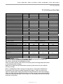
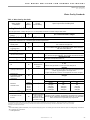
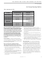
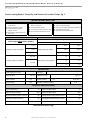
TO VF/VD Physical Data Table
Note 1: A strainer is required on the ENTERING WATER connection to the DOAS unit.
The strainer must be provided and installed by others.
The strainer must be 60 mesh (250 Micron) or fi ner.
Failure to install a properly sized strainer can lead to premature fouling and possible failure
of a brazed plate heat exchanger.
DOAS units installed and operated without a properly sized strainer will not qualify for
warranty coverage.
Note 2: A dedicated 115 VAC, 15 Amp circuit (by others) is required on all DOAS units
for operation of the factory installed evaporator heat tape(s). Failure to connect heat
tape(s) to a proper power supply may lead to freezing of the water in the heat exchanger.
Failure of, and/or damage caused by the failure of a heat exchanger due to freezing will be
exempt from warranty coverage if the heat tapes are not properly connected and working
at the time of the failure.
Model 4 5 8 10
Fan motor available H.P. 0.5/1.0/1.5/2.0 0.5/1.0/1.5/2.0 0.5/1.0/1.5 0.5/1.0/1.5/2.0
Blower wheel size 11-04/11-10 11-04/11-10 11-04/11-10 11-10
Compressor type/qty Scroll, 1 ea. Scroll 2ea. (1 tandem set)
Factory charge lb/unit
HFC-410A Tranquility units 13 [208] 15 [240] 20 [320] 26 416]
Water Connection Size “ O.D. 7/8" 1/18" 1 3/8" 13/8"
Water Flow Rate GPM 17 19 26 34
Water Pressure Drop PSI/Ft 5.3/12.23 4.0/9.23 5.4/12.46 6.6/15.22
Condensate Connection Size 1" 1" 1" 1"
Miscellaneous Data
Filter qty/size (1) 25 X 29 X 4 (1) 25 X 29 X 4 (2) 20 X 25 X 4 (2) 20 X 25 X 4
Filter Type Merv 11, Pleated
Operating Weight 626 643 940 1002
Shipping Weight 639 666 965 1033
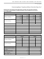
Model 15 20 25 30
Fan motor available H.P. 1.0/1.5/20./3.0 1.0/1.5/20./3.0/5.0/7.5 1.0/1.5/20./3.0/5.0/7.5 1.0/1.5/20./3.0/5.0/7.5
Blower wheel size 11-10/12-12 APAF18-T2 APAF18-T2 APAF18-T2
Compressor type/qty Scroll 2ea. (1 tandem set)
Factory charge lb/unit
HFC-410A Tranquility units 40 [640] 62 [992] N/A 87 [1392]
Water Connection Size “ O.D. 15/8" 25/8" 25/8" 25/8"
Water Flow Rate GPM 49 69 84 102
Water Pressure Drop PSI/Ft 9.4/21.68 6.2/14.30 6.2/14.30 7.1/16.38
Condensate Connection Size 1" 1" 1" 1"
Miscellaneous Data
Filter qty/size (4) 20 X 20 X 4
(3) 20 X 24 X 4 (3) 24 X
24 X 4
(3) 20 X 24 X 4 (3) 24
X 24 X 4
(3) 20 X 24 X 4 (3) 24 X
24 X 4
Filter Type Merv 11, Pleated
Operating Weight 1401 2467 2652 2771
Shipping Weight 1444 2569 2742 2886

CLIMATEMASTER WATER-SOURCE HEAT PUMPS
Vertical DOAS
Rev.: 01/31/13
18
ClimateMaster Water-Source Heat Pumps
Vertical Installation
Condensate Piping – Vertical Units - The condensate
drain connection is on the side of the DOAS unit. Pitch
the drainpipe a minimum of 1/4 inch per linear foot, and
support it at least every 5 feet. If the drain runs through
an unconditioned space, you must install heat tracing to
prevent the moisture in the drain from freezing. NOTE:
While its supply blower runs, the inside of the DOAS Unit
operates at a negative pressure. Your Tranquility unit has
an internal factory-installed p-trap in the condensate
drain to prevent condensate from being drawn into the
cabinet of the DOAS unit.
CAUTION!
CAUTION! Ensure condensate line is pitched toward drain
1/8 inch per ft [11mm per m] of run.

THE SMART SOLUTION FOR ENERGY EFFICIENCY
Vertical DOAS
Rev.: 01/31/13
19
climatemaster.com
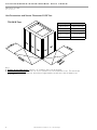
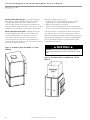
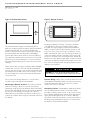
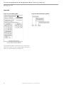
The total air fl ow of a ClimateMaster 20-ton through
30-ton system should be checked by measuring the air
pressure drop across only the reheat coil as shown in
Figure 2. Note: Port #1 is measuring the internal cabinet
pressure downstream of the evaporator (high side)
and port #2 is added to the discharge duct in the fi eld,
downstream of the reheat coil (low side).
A Magnehelic® or inclined manometer with a range
of 0.0-1.0 inch water column will work well for this.
ClimateMaster DOAS units feature an adjustable blower
sheave to simplify air balancing. Utilize the following
procedure to determine system airfl ow:
1. Check the condition of the air fi lters and coils. Assure
that they are clean.
2. Check for any obvious restrictions in the ductwork.
3. Drive the outdoor air damper open, start the supply
air blower and energize the fi eld-installed exhaust air
blower by turning on the “occupied” switch.
4. Use a Magnehelic® or inclined manometer to
measure the air pressure drop across ports #1 and #2.
Refer to Figures 1 & 2 to determine your unit cabinet
confi guration and the air sampling port locations.
Compare this value to the value printed on the air fl ow
label on the side of the DOAS unit.
5. Change the air fl ow, if necessary, by adjusting the
motor pulley or any balancing dampers in the fi eld-
installed ductwork.
Always measure the current draw of the blower motor
after you make any changes to the air fl ow quantity. If
the motor draws more than its FLA rating but the total
air fl ow is still low, check the resistance of the ductwork.
Verify that all grilles and dampers have been opened
and that there are no sudden turns or restrictions in the
ductwork.
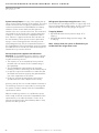
Duct System Installation
Duct System Installation - Duct design and installations
should conform to the latest ASHRAE and SMACNA
low velocity duct standards Undersized, restrictive
ductwork with abrupt turns or transitions can decrease
the effi ciency and the moisture removal capacity of
your DOAS unit. Size the ductwork for an acceptable air
pressure drop at the airfl ow volume of your DOAS unit.
Use neoprene fl ex connectors when you attach ductwork
to the DOAS unit to prevent transmission of excess
vibration and noise.
Select the grilles, registers and diffusers for low static
pressure loss, required throw distance, and the specifi ed
CFM rating. You can fi nd this information in most grille
manufacturer’s catalogs. If you are installing the grilles in
a corrosive environment, choose components made from
anodized aluminum.
If you must install ductwork in an unconditioned area, use
fi berglass duct wrap with vapor barrier facing. You must
install the outdoor air intake away from any sources of
airborne contamination such as exhaust fans or plumbing
vents. You can use galvanized sheet metal ducts for
most applications. However, you should use aluminum
or stainless steel ducts for extreme applications such as
chemical-laden environments.
Unit Air Flow - Each ClimateMaster DOAS unit is
designed to operate at a specifi ed air fl ow rate. System
air fl ow must be checked prior to troubleshooting the
refrigeration circuit to assure that such problems are not
actually caused by improper unit air fl ow.
Problems with excessive airfl ow include:
• Reduction in moisture removal capacity.
• High amperage draw by the blower motor.
• Water carry over from evaporator coil.
• Excessive unit noise levels.
Problems with inadequate airfl ow include:
• Violation of ventilation codes.
• Risk of evaporator coil freezing.
• Possibility of premature compressor failure.
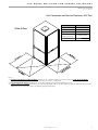
Determining System Air Flow - The total air fl ow of a
ClimateMaster 4-ton through 15-ton system should be
checked by measuring the air pressure drop across both
the evaporator and reheat coil between port #1 (low side)
and port #2 (high side) as shown in Figure 1.
WARNING!
WARNING! - Disconnect power before adjusting blower. Failure
to disconnect power could result in death or serious injury.

CLIMATEMASTER WATER-SOURCE HEAT PUMPS
Vertical DOAS
Rev.: 01/31/13
20
ClimateMaster Water-Source Heat Pumps
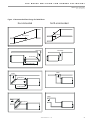
Figure 1: Air Balance Ports for Models 4 - 15 Ton
Cabinets
Figure 2: Air Balance Ports for Models 20 - 30 Ton
Cabinets
Recommended Duct Designs - You must use proper
duct design to ensure that the DOAS unit operates
effi ciently and without problems. Undersized or
restrictive ducts reduce the system air fl ow which can
cause premature compressor failure. Use the proceeding
diagrams as a guide when you design the duct system.
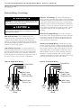
Blower Adjustment Procedure - Change the blower
speed by adjusting the motor pulley. To adjust the
variable pitch pulley, fi rst loosen the set screw. To
slow down the blower, turn the outer pulley face
counterclockwise (to decrease its pitch diameter). To
speed up the blower, turn the outer pulley face clockwise
(to increase its pitch diameter).
WARNING!
WARNING! - Disconnect power before adjusting blower.
Failure to disconnect power could result in death or serious
injury.
After every adjustment be sure to:
• Tighten the set screw against the flat spot on the
pulley hub so you don’t damage any threads.
• Adjust the belt tension if needed.
• Check to assure that the blower motor current draw
does not exceed the rating printed on the rating plate.
If the blower motor current draw exceeds its rating but
your airfl ow is still too low, the static pressure losses in
the ductwork and grilles may be higher than the unit was
designed for. If this happens, consult the ClimateMaster
Service Department. Please be prepared with system
serial and model number.
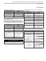
Page is loading ...
Page is loading ...
Page is loading ...
Page is loading ...
Page is loading ...
Page is loading ...
Page is loading ...
Page is loading ...
Page is loading ...
Page is loading ...
Page is loading ...
Page is loading ...
Page is loading ...
Page is loading ...
Page is loading ...
Page is loading ...
Page is loading ...
Page is loading ...
Page is loading ...
Page is loading ...
Page is loading ...
Page is loading ...
Page is loading ...
Page is loading ...
-
 1
1
-
 2
2
-
 3
3
-
 4
4
-
 5
5
-
 6
6
-
 7
7
-
 8
8
-
 9
9
-
 10
10
-
 11
11
-
 12
12
-
 13
13
-
 14
14
-
 15
15
-
 16
16
-
 17
17
-
 18
18
-
 19
19
-
 20
20
-
 21
21
-
 22
22
-
 23
23
-
 24
24
-
 25
25
-
 26
26
-
 27
27
-
 28
28
-
 29
29
-
 30
30
-
 31
31
-
 32
32
-
 33
33
-
 34
34
-
 35
35
-
 36
36
-
 37
37
-
 38
38
-
 39
39
-
 40
40
-
 41
41
-
 42
42
-
 43
43
-
 44
44


ClimateMaster TOV User manual
- Type
- User manual
- This manual is also suitable for
Ask a question and I''ll find the answer in the document
Finding information in a document is now easier with AI
Related papers
-
ClimateMaster TOH/R Install Manual
-
-
-
-
-
-
ClimateMaster Horizontal/Vertical WSHP Install Manual
-
-
-
Other documents
-
EZ-FLO 98587 Installation guide
-
Greenheck XG-XG-Fan User manual
-
Bosch SV-LV036-1 Operating instructions
-
COMFORT-AIRE HEH030A1D01ALB Installation, Operation & Maintenance Manual
-
 evoheat Old Solace Universal Owner's manual
-
HQ W3-65013-HQN Datasheet
-
Carrier GB Owner's manual
-
COMFORT-AIRE HEH048C1D00JRB-CY Installation, Operation & Maintenance Manual
-
 RenewAire DN Series Packaged Refrigeration Supplement Owner's manual
-
Bryant GC Owner's manual

