Page is loading ...

Outdoor Model DN3RT Shown
Indoor Model DN2IN Shown
DN2
DN3
DN5
DN SERIES DOAS
Shipping, Rigging, Hoisting, and Assembly Manual

1.800.627.44992
DN-Series
DOAS
This unit is intended for general ventilating only. Do not use
to exhaust hazardous or explosive materials and vapors. Do
not connect this equipment to range hoods, fume hoods or
collection systems for toxics.
NOTICE
Risk of DAMAGE TO DOAS CABINET
Incorrect lifting can cause damage to the unit.
Do not lift joined unit by the 4 corner lifting lugs only. Secure
lifting cables to the center lifting lugs also.
All lifting lugs provided must be used. Never lift the unit or
modules from the top of the unit.
NOTICE
Risk of DAMAGE TO ENTHALPIC CORES
Whenever working within the DOAS cabinet, protect the enthal-
pic cores from accidental damage. The core media is subject to
damage from dropped tools or other foreign objects.
NOTICE
This unit is for ventilating finished structures only. It is not
to be used until after all construction has been completed
and construction debris and dust are cleaned from the
Occupied Space.
NOTICE
IMPORTANT
If this unit is installed in an area where it may draw air from
a nearby fuel-burning device such as a gas furnace or water
heater, verify that the air being extracted by the DOAS does not
conflict with proper operation of the fuel-burning device.
This equipment is to be installed by following Industry Best
Practices and all applicable codes. Any damage to compo-
nents, assemblies, subassemblies or the cabinet which is
caused by improper installation practices will void
the warranty.
NOTICE
CAUTION
It is the installers responsibility to select equipment,
structures, and materials suitable to support the loads and
substrates involved with installation. Secure the unit so it
cannot fall or tip in the event of accident, structural failure,
or earthquake. Do not store or stack items on the unit when
installed.
WARNING
RISK OF DEATH 0R SERIOUS INJURY
Hoisting heavy equipment overhead is inherently dangerous.
Failure to properly rig the DOAS for hoisting or the use of in-
correct rigging equipment may result in the DOAS falling during
hoisting.
Improper work procedures may result in death or serious injury
to workers. Rigging, hoisting and assembly are to be performed
by skilled and experienced personnel. OSHA-approved work
guidelines are to be strictly followed.
Before proceeding with installation, read all instructions, verify-
ing that all the parts are included.
The information in this manual is provided as a guideline and
does not necessarily meet all local codes. It is the installer’s re-
sponsibility to comply with all local codes and OSHA-approved
safety practices.

31.800.627.4499
DN-Series DOAS
READ AND SAVE THIS MANUAL/LIRE ET CONSERVER CE MANUEL
In the unlikely event that factory assistance is ever required, information located on the unit label will
be needed.
UNIT INFORMATION
UNIT LABEL (TYPICAL)
UNIT INFORMATION
D - -- -N J - -
SERIAL NUMBER:
OPTION CODE:
SO #:

1.800.627.44994
DN-Series
DOAS
TABLE OF CONTENTS
1.0 OVERVIEW 6
2.0 SHIPPING/RECEIVING/HANDLING 7
2.1 OFF-LOADING ........................................................ 7
2.2 FORKLIFT USE ....................................................... 7
2.3 HOISTING .............................................................. 8
2.4 DN2IN DRAWINGS ............................................... 10
2.4.1 DN2IN Dimensioned Drawing .............................................10
2.4.2 DN2IN Center of Gravity Drawing ...................................... 11
2.5 DN2RT DRAWINGS ............................................... 12
2.5.1 DN2RT Dimensioned Drawing ............................................ 12
2.5.2 DN2RT Center of Gravity Drawing ..................................... 13
2.5.3 DN2RT with Packaged Refrigeration
Dimensioned Drawing ....................................................... 14
2.5.4 DN2RT with Packaged Refrigeration Center of
Gravity Drawing ................................................................15
2.5.5 DN2RT Full-Sized Curb Drawing ........................................16
2.5.6 DN2RT Curb Mounting Drawing ......................................... 16
2.6 DN3IN DRAWINGS ............................................... 17
2.6.1 DN3IN Dimensioned Drawing............................................. 17
2.6.2 DN3IN Center of Gravity Drawing ...................................... 18
2.7 DN3RT DRAWINGS ............................................... 19
2.7.1 DN3RT Dimensioned Drawing ............................................ 19
2.7.2 DN3RT Center of Gravity Drawing ...................................... 20
2.7.3 DN3RT with Packaged Refrigeration
Dimensioned Drawing .......................................................21
2.7.4 DN3RT with Packaged Refrigeration Center of
Gravity Drawing ................................................................22
2.7.5 DN3RT Full-Size Curb Drawing ..........................................23
2.7.6 DN3RT Curb Mounting Drawing .........................................23
2.8 DN5IN DRAWINGS ............................................... 24
2.8.1 DN5IN Dimensioned Drawing ............................................24
2.8.2 DN5IN Center of Gravity Drawing ......................................25
2.9 DN5RT DRAWINGS ............................................... 26
2.9.1 DN5RT Dimensioned Drawing ............................................26
2.9.2 DN5RT Center of Gravity Drawing .....................................27
2.9.3 DN5RT with Packaged Refrigeration
Dimensioned Drawing ....................................................... 28
2.9.4 DN5RT with Packaged Refrigeration Center of
Gravity Drawing ................................................................29
2.9.5 DN5RT Full-Size Curb Drawing .......................................... 30
2.9.6 DN5RT Curb Mounting Drawing .........................................30
3.0 INSTALLATION PREPARATION 32
3.1 DRAIN TRAP PREPARATION .................................. 32
3.2 UNIT STORAGE .................................................... 32
3.3 ROOFTOP CURBS ................................................. 32
3.4 CURB CLIPS ........................................................ 32
3.5 EQUIPMENT RAILS ............................................... 33
3.6 PRE-POSITION DUCTWORK .................................. 33
3.7 LATERAL GROUND MOVEMENT ............................ 33
3.8 UNIT PLACEMENT ................................................ 33
3.9 INSTALLATION OF HOODS .................................... 34
3.9.1 Outside Air Hood .............................................................. 34
3.9.2 Exhaust Air Hood ............................................................. 34
3.10 UTILITY AND MECHANICAL CONNECTIONS ......... 34

51.800.627.4499
DN-Series DOAS
TABLE OF CONTENTS
TABLE OF ILLUSTRATIONS
Figure 2.3.0 Example of Minimum Hoisting Requirements .................................................................... 9
Figure 3.4.0 Curb Clips Typical Installation ........................................................................................32
Figure 3.9.0 Outside Air Hood (Typical) .............................................................................................34
Figure 3.9.1 Exhaust Air Hood (Typical) .............................................................................................34
Figure 3.10.0 Piping Penetrations Drawing A .....................................................................................35
Figure 3.10.1 Piping Penetrations Drawing B .....................................................................................35

1.800.627.44996
DN-Series
DOAS
TABLE OF CONTENTS
1.0 OVERVIEW
NOTE: Dimensions
shown are
approximate and
are for units with
1" thick walls. For units
with 2" thick walls or
unit specific dimensions
and weights see the unit
submittal.
A Dedicated Outdoor Air System, or DOAS, is a large air handling unit containing an energy
recovery core, two fans and optional heating/cooling equipment. The walls, floor and roof are
all double-wall sheet metal panels with foam insulation. It has a permanently attached base,
equipped with lifting lugs. The base also has openings to permit use of a forklift with extended
forks to lift the unit from either the sides or the ends.
RenewAire DOASs come in two different versions, either the Indoor Series or the Rooftop
Series. Rooftop Series can have the Packaged Refrigeration option. Each series is available
in three different sizes (DN2, DN3, DN5) but they may also be configured at the factory into a
shorter unit with limited options.
Indoor Series includes:
DN2IN: 126" L x 60.75" W x 71.875" H
DN3IN: 147.875" L x 90.125" W x 71.875" H
DN5IN: 174" L x 103.75" W x 88.875" H
Rooftop Series without Packaged Refrigeration includes:
DN2RT: 151.625" L x 76.625" W x 73.125" H
DN3RT: 174.875" L x 106.125" W x 75.125" H
DN5RT: 205.125" L x 126.375" W x 92.125" H
Rooftop Series with Packaged Refrigeration includes:
DN2RT: 189 3/8" L x 76 3/4" W x 76 3/4" H
DN3RT: 210 3/4" L x 106 1/8" W x 78 1/2" H
DN5RT: 247 3/8" L x 126 3/8" W x 95" H
See the Center of Gravity drawings in Section 2.0 of this manual for unit weights and to see the
approximate center of gravity for each unit.
See the submittal to verify the unit model, unit dimensions, and approximate unit weight.
The rooftop version is normally placed on a 14" high curb (ordered and delivered separately) or
customer-provided equipment rails, while the indoor version may be placed on owner-provided
supports. All units must generally be elevated above ground level in order to provide clearance
for drain traps or water drainage.

71.800.627.4499
DN-Series DOAS
SHIPPING/RECEIVING
2.0 SHIPPING/RECEIVING/HANDLING
All DOAS units are assembled at the factory and palletized for shipment via common carrier.
The DOAS will be on one large pallet and needed accessories such as outdoor air hoods are
factory-assembled and shipped on a separate pallet at the same time. Some small accessories
may be packed and stored inside the DOAS itself. It is the customer’s responsibility to
coordinate delivery of the shipment and provide any needed equipment for off-loading and
placement of the unit. It is the customer’s/installer’s responsibility to provide needed equipment
and skilled/experienced personnel to off-load the DOAS.
Note that when the shipment is delivered, the shipment MUST BE INSPECTED for any shipping
damage or missing items. If any damage is found or if items are missing, notify your RenewAire
dealer before accepting the shipment. If damage is found, take digital pictures of the damage.
All discrepancies must be noted on the Bill of Lading.
2.1 OFF-LOADING
The DOAS can be handled with a forklift or crane, depending on the unit size and method of
shipment. A crane can be used to hoist a rooftop unit directly to its intended location. Indoor
units can sometimes be placed directly on their supports if the building roof is not yet in
place. In other cases, indoor units will require lateral ground movement. When lateral ground
movement is required, provision must be made to place the unit on a hard, level surface. Do not
pull the unit by its lifting lugs.
2.2 FORKLIFT USE
The DOAS unit base has openings in the sides and the ends for insertion of forklift forks. When
a forklift is used to move or handle the DOAS, care must be taken to ensure that the forks
extend all the way across the unit.
When lifting unit, forklift extensions must be used and a minimum length of 72" for DN2 and
96" for DN3 and DN5.
When lifting DOAS off the pallets:
u If entering from the side of the DOAS, ensure forks extend in far enough as to catch the
furthest away stringer with fork extensions.
u If entering from the front of the unit, ensure forks extend all the way through the unit.

1.800.627.44998
DN-Series
DOAS
u The unit comes equipped with base rail lifting lugs at the lower 4 corners and in the middle of
the unit.
u Each lifting lug has a 2" diameter hole which will accommodate a 1.5" dia. schedule 40 steel
pipe (not provided).
u Unit shall be lifted by cables (slings) attached to all of the lifting lugs.
u If cables or chains are used to lift the unit they must be the same length. Care should be
taken not to damage the cabinet, dampers or roof.
u Adjustable spreader bars should be used to properly support the unit in order to distribute
the load thus applying an even vertical lifting force to all of the lifting lugs. This will prevent
structural damage to the unit.
u Provide additional blocking or covering as required.
u Secure hooks and cables at all lifting points.
u Take up slack in cables gradually as to avoid sudden movements as this may cause the unit
to shift.
u Suspending the unit for an extended period of time is not recommended and it is advised to
place the unit as soon as possible after lifting.
u Do not lift in high winds.
u RenewAire will not be responsible for any damage during the rigging, lifting, or installing of
the DOAS.
u Refer to Center of Gravity drawings in Section 4.0 of this manual for approximate center of
gravity and all corner weights.
SHIPPING/RECEIVING
NOTE: Whenever
a unit is rigged for
lifting, whether by
means of a forklift or a
crane, a test-lift should
be performed. Raise the
unit slightly and check
all rigging and verify that
the raised unit is LEVEL.
If the rigging is coming
into contact with the unit
cabinet or if the unit is out
of level, replace the unit
and correct the rigging
equipment.
WARNING
RISK OF DEATH 0R SERIOUS INJURY
Hoisting heavy equipment overhead is inherently dangerous. Failure to properly rig the DOAS for
hoisting or the use of incorrect rigging equipment may result in the DOAS falling during hoisting.
Improper work procedures may result in death or serious injury to workers. Rigging, hoisting
and assembly are to be performed by skilled and experienced personnel. OSHA-approved work
guidelines are to be strictly followed.
Before proceeding with installation, read all instructions, verifying that all the parts are included.
The information in this manual is provided as a guideline and does not necessarily meet all local
codes. It is the installer’s responsibility to comply with all local codes and OSHA-approved
safety practices.
2.3 HOISTING
Note that RenewAire does not provide specific instructions for hoisting and moving the DOAS
because all job sites are different and available handling equipment will vary. It is the rigger’s
responsibility to properly and safely move the DOAS.

91.800.627.4499
DN-Series DOAS
u All hoisting hardware must be properly load-rated. See Center of Gravity drawings in Section
4.0 of this manual.
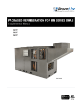
u All lifting lugs must be used to properly support the unit during hoisting.
u All hoisting slings must provide uniform lift on each lifting lug.
u All hoisting slings must be completely vertical and cannot touch the cabinet during hoisting.
u Hoisting slings are to be attached to the lifting lugs with appropriate hardware such as
shackles.
IMPORTANT
Do not pull unit by lifting lugs. Handle the unit with a forklift or crane.
FIGURE 2.3.0 EXAMPLE OF MINIMUM HOISTING REQUIREMENTS
IT IS THE INSTALLING CONTRACTOR’S RESPONSIBILITY TO PROPERLY RIG AND HOIST THE UNIT.
RENEWAIRE DOES NOT GIVE SPECIFIC INSTRUCTIONS FOR PROPER RIGGING BECAUSE ALL JOB
SITES ARE DIFFERENT.
SHIPPING/RECEIVING
Most deliveries and installations occur at the same time, meaning that the DOAS will be
hoisted off the delivery truck and then go immediately to its final location. In these cases, the
DOAS packing materials will be loosened or removed and the DOAS will be hoisted without
any attached packing or shipping materials. If the DOAS must be stored for a period before
placement in its final location, it may be preferable to leave the DOAS on its shipping pallet.
HOISTING BEAM (TYPICAL)
SPREADER BARS (TYPICAL)
HOISTING SLINGS (TYPICAL)

1.800.627.449910
DN-Series
DOAS
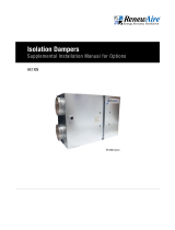
6 7/8"
119 7/8" Case
126" Overall
FRONT VIEW
SA
Coil Connections
Locations Vary
OA
RA
1" NPT
Condensate Drain
(opt)
RA
SA
(opt)
Disconnect
Switch and
EBOX
OA
(opt)
(opt)
EA
Gas Heat
Connections
Locations Vary
12 1/8"
11 7/8"
46"
12 1/8"
RIGHT VIEW
RA Duct Flange
24" x 16"
OA Damper
24" x 16" Duct Flange
18 5/8"
14 7/8"
LEFT VIEW
EA
(2) 7/8" Holes
for Power and Controls
Field Wiring
SA Duct Flange
24" x 16"
Gas Heat
Combustion
Exhaust
Connection
Gas Heat
Combustion
Air Intake
46"
48 3/4"
71 7/8"
Overall
66 7/8"
Case
BACK VIEW
EA Damper
20" x 16" Duct Flange
60 3/4"
Overall
27"
52 1/4"
40" Minimum
Service Area
36" Minimum
Service Area
119 7/8" Minimum
Service Area
14"
6"
30"
14 1/8"
12 1/8"
24 1/8"
48"
Case
22 3/4"
Minimum
Service
Area
TOP VIEW
OA Damper (Roof; Optional)
24" x 16" Duct Flange
RA (Floor; Optional)
24" x 16" Duct Flange
EA Damper (Roof; Optional)
20" x 16" Duct Flange
SA (Floor; Optional)
24" x 16" Duct Flange
Door
Swing
Model: DN-2JIN ERV+COIL+HEAT 1"
Drawing Type: Unit Dimension
Version: NOV18
ABBREVIATIONS
EA: Exhaust Air to outside
OA: Outside Air intake
RA: Room Air to be exhausted
SA: Supply Air to inside
INSTALLATION ORIENTATION
Unit must be installed in orientation
shown.
NOTE
1. UNLESS OTHERWISE SPECIFIED,
DIMENSIONS ARE ROUNDED TO THE
NEAREST EIGHTH OF AN INCH.
2. SPECIFICATIONS MAY BE SUBJECT
TO CHANGE WITHOUT NOTICE.
3. FOR PIPE CONNECTION DETAILS
REFER TO CORES OR UNIT SELECTION
SUBMITTAL.
4. UNIT, UNIT DOORS, AND COILS
CANNOT BE MIRRORED.
5.FOR PROJECT SPECIFIC DRAWINGS
REFER TO PROJECT SUBMITTAL.
Coil Options: DX, CW, HGRH
Heat Options: HW, Electric, Gas, Steam
2.4 DN2IN DRAWINGS
SHIPPING/RECEIVING
2.4.1 DN2IN Dimensioned Drawing

111.800.627.4499
DN-Series DOAS
MODELS L W A B UNIT LF LR RR RF
ERV 70.86 48 36.85 23.69 1250 329 321 296 304
ERV+Coil 95.36 48 51.51 22.9 1750 494 451 384 421
ERV+EH 95.36 48 47.21 23.18 1600 410 383 390 418
ERV+GH 95.36 48 51.11 21.57 1750 516 421 365 447
LR RR ERV+Coil+EH 119.89 48 60.41 22.79 2100 556 502 495 547
ERV+Coil+GH 119.89 48 64.46 21.55 2250 667 543 467 573
ERV+Coil+ST 119.89 48 63.53 22.06 2250 644 548 486 572
MODELS L W A B UNIT LF LR RR RF
ERV 72.86 50 37.85 24.69 1330 350 341 316 324
LF RF ERV+Coil 97.36 50 52.51 23.9 1850 521 477 407 445
ERV+EH 97.36 50 48.21 24.18 1700 435 407 415 443
ERV+GH 97.36 50 52.11 22.57 1850 543 447 388 472
ERV+Coil+EH 121.89 50 61.41 23.79 2220 586 532 524 577
ERV+Coil+GH 121.89 50 65.46 22.55 2370 699 574 495 602
ERV+Coil+ST 121.89 50 64.53 23.06 2370 676 579 514 601
OPTIONS
RECIRC
VFD
DN‐2‐IN1"CABINETUNITWEIGHTS(LBS)
DN‐2‐IN2"CABINETUNITWEIGHTS(LBS)
DN‐2‐IN
CenterofGravity"A"and"B"Dimensions+/‐2"
CenterofGravity"A"and"B"Dimensions+/‐2"
ADDITIONALWEIGHTSFOROPTIONS(LBS)
UNIT
25
150
AddtheadditionalweightsforoptionstotheUnitWeightstodetermineUnitandCornerweightsforaspecificunit.
2.4.2 DN2IN Center of Gravity Drawing
SHIPPING/RECEIVING

1.800.627.449912
DN-Series
DOAS
2.5 DN2RT DRAWINGS
123 7/8" Roof
151 5/8" Overall
8 7/8"
FRONT VIEW
SA
OA
RA
1" NPT
Condensate Drain
(opt)
RA
SA
(opt)
Disconnect Switch
and EBOX
Gas Heat Connections
Locations Vary
12 1/8"
13 7/8"
48"
Case
RIGHT VIEW
RA Duct Flange
24" x 16"
16 7/8"
18 5/8"
LEFT VIEW
EA
(2) 7/8" Holes
for Power and Controls
Field Wiring
SA Duct Flange
24" x 16"
Gas Heat
Combustion
Air Intake
Gas Heat
Combustion
Exhaust
73 1/8"
Overall
119 7/8" Case
BACK VIEW
Coil Connections
Locations Vary
52 1/8"
Roof
76 3/4"
Overall
119 7/8" Minimum
Service Area
40" Minimum
Service Area
26 1/8"
16"
32 5/8"
16"
36" Minimum
Service Area
74" Minimum
Service Area
TOP VIEW
RA (Floor; Optional)
24" x 16"
Door
Swing
SA (Floor; Optional)
24" x 16"
Model: DN-2JRT ERV+COIL+HEAT 1"
Drawing Type: Unit Dimension
Version: AUG19
ABBREVIATIONS
EA: Exhaust Air to outside
OA: Outside Air intake
RA: Room Air to be exhausted
SA: Supply Air to inside
INSTALLATION ORIENTATION
Unit must be installed in orientation
shown.
NOTE
1. UNLESS OTHERWISE SPECIFIED,
DIMENSIONS ARE ROUNDED TO THE
NEAREST EIGHTH OF AN INCH.
2. SPECIFICATIONS MAY BE SUBJECT
TO CHANGE WITHOUT NOTICE.
3. FOR PIPE CONNECTION DETAILS
REFER TO CORES OR UNIT SELECTION
SUBMITTAL.
4. UNIT, UNIT DOORS, AND COILS
CANNOT BE MIRRORED.
5. FOR CURB DETAILS REFER TO CURB
DRAWING.
6. FOR PROJECT SPECIFIC DRAWINGS
REFER TO PROJECT SUBMITTAL.
Coil Options: DX, CW, HGRH
Heat Options: HW, Electric, Gas, Steam
SHIPPING/RECEIVING
2.5.1 DN2RT Dimensioned Drawing

131.800.627.4499
DN-Series DOAS
2.5.2 DN2RT Center of Gravity Drawing
MODELS L W A B UNIT LF LR RR RF
ERV 70.58 48 35.37 24.19 1500 373 379 377 371
ERV + Coil 95.26 48 50.32 25.08 2050 517 566 505 462
ERV + EH 95.26 48 45.61 23.75 1825 441 432 471 481
ERV + GH 95.26 48 49.09 22.32 2000 551 479 451 519
LR RR ERV + Coil + EH 119.89 48 58.44 24.55 2325 554 580 609 582
ERV + Coil + GH 119.89 48 62.1 23.35 2525 672 636 592 625
ERV + Coil + ST 119.89 48 59.54 23.78 2425 608 597 605 616
MODELS L W A B UNIT LF LR RR RF
ERV 72.58 50 36.37 25.19 1580 393 399 397 391
LF RF ERV + Coil 97.26 50 51.32 26.08 2150 543 592 530 486
ERV + EH 97.26 50 46.61 24.75 1925 466 457 496 506
ERV + GH 97.26 50 50.09 23.32 2100 577 504 475 543
ERV + Coil + EH 121.89 50 59.44 25.55 2445 583 609 640 613
ERV + Coil + GH 121.89 50 63.1 24.35 2645 702 667 621 654
ERV + Coil + ST 121.89 50 60.54 24.78 2545 638 626 635 646
OPTIONS
RECIRC
VFD
DN-2-RT 1" CABINET UNIT WEIGHTS (LBS)
DN-2-RT
Center of Gravity "A" and "B" Dimensions +/- 2"
DN-2-RT 2" CABINET UNIT WEIGHTS (LBS)
Center of Gravity "A" and "B" Dimensions +/- 2"
UNIT
25
150
Add the additional weights for options to the Unit Weights to determine Unit and Corner weights for a specific unit.
Dashed line is OD of unit base.
ADDITIONAL WEIGHTS FOR OPTIONS (LBS)
SHIPPING/RECEIVING

1.800.627.449914
DN-Series
DOAS
8 7/8"
123 7/8" Roof
189 3/8" Overall
162 5/8"
FRONT VIEW
SA
OA
RA
1" NPT
Condensate Drain
(opt)
RA
SA
(opt)
Gas Heat Connections
Locations Vary
Access to Disc.
Switch and EBOX
13 7/8"
12 1/8"
48"
Case
RIGHT VIEW
RA Duct Flange
24" x 16"
Lift Lug
8 Places
18 3/4"
17"
Allow Min. 48"
Clearance
Above Fan
LEFT VIEW
EA
(2) 7/8" Holes
for Power and Controls
Field Wiring
SA Duct Flange
24" x 16"
Gas Heat
Combustion
Air Intake
Gas Heat
Combustion
Exhaust
76 3/4"
Overall
119 7/8" Case
BACK VIEW
Condenser Fan
Screen
Swing
Screen
Swing
76 3/4"
Overall 52 1/8"
Roof
120 1/4" Minimum
Service Area
40" Minimum
Service Area
26 1/8"
16"
36" Minimum
Service Area
74" Minimum
Service Area
16"
32 1/8"
TOP VIEW
RA (Floor; Optional)
24" x 16"
Door
Swing
SA (Floor; Optional)
24" x 16"
CA
Model: DN-2JRT-PKGD ERV+COIL+HEAT 1"
Drawing Type: Unit Dimension
Version: MAY20
ABBREVIATIONS
EA: Exhaust Air to outside
OA: Outside Air intake
RA: Room Air to be exhausted
SA: Supply Air to inside
CA: Condenser Air
INSTALLATION ORIENTATION
Unit must be installed in orientation shown.
NOTE
1. UNLESS OTHERWISE SPECIFIED, DIMENSIONS ARE
ROUNDED TO THE NEAREST EIGHTH OF AN INCH.
2. SPECIFICATIONS MAY BE SUBJECT TO CHANGE
WITHOUT NOTICE.
3. FOR PIPE CONNECTION DETAILS REFER TO
CORES OR UNIT SELECTION SUBMITTAL.
4. UNIT, UNIT DOORS, AND COILS CANNOT BE
MIRRORED.
5. FOR CURB DETAILS REFER TO CURB DRAWING.
6. FOR PROJECT SPECIFIC DRAWINGS REFER TO
PROJECT SUBMITTAL.
7. SCREEN SWING AREA VARIES DEPENDING ON
HORIZONTAL OR VERTICAL DUCT CONNECTIONS.
Coil Options: DX, HGRH
Heat Options: Electric, Gas, HW, Steam
SHIPPING/RECEIVING
2.5.3 DN2RT with Packaged Refrigeration Dimensioned Drawing

151.800.627.4499
DN-Series DOAS
2.5.4 DN2RT with Packaged Refrigeration Center of Gravity Drawing
MODELS L W A B UNIT LF LR RR RF
LR RR ERV+Coil 95.26 48 58.255 24.271 2500 756 773 491 480
ERV+Coil+EH 119.89 48 58.98 23.48 2775 697 668 690 720
ERV+Coil+GH 119.89 48 61.74 22.95 2975 800 733 690 753
ERV+Coil+ST 119.89 48 60.87 22.63 2875 772 688 667 748
MODELS L W A B UNIT LF LR RR RF
ERV+Coil 97.26 50 59.255 25.271 2610 786 804 515 504
ERV+Coil+EH 121.89 50 59.98 24.48 2900 728 699 721 752
LF RF ERV+Coil+GH 121.89 50 62.74 23.95 3100 831 764 721 784
ERV+Coil+ST 121.89 50 61.87 23.63 3000 803 720 698 779
OPTIONS
RECIRC
VFD
UNIT
25
150
CenterofGravity"A"and"B"Dimensions+/‐2"
AddtheadditionalweightsforoptionstotheUnitWeightstodetermineUnitandCornerweightsforaspecificunit.
DN‐2‐RTPKGD1"CABINETUNITWEIGHTS(LBS)
CenterofGravity"A"and"B"Dimensions+/‐2"
DN‐2‐RT2"PKGDCABINETUNITWEIGHTS(LBS)
DashedlineisODofunitbase.
ADDITIONALWEIGHTSFOROPTIONS(LBS)
DN‐2‐RTPKGD
SHIPPING/RECEIVING

1.800.627.449916
DN-Series
DOAS
2.5.5 DN2RT Full-Sized Curb Drawing
2.5.6 DN2RT Curb Mounting Drawing
A
A
5.97
Inside of base
to curb
2.44
Inside of base
to curb
SECTION A-A
SCALE 1 : 18
Allow Drain Pan
connection to be
outside of curb
Understructure
of base
sits on top
of curb
Understructure
of base
sits on top
of curb
RenewAire LLC
SCALE:1:48
SIZE
DWG. NO.
A
MATERIAL:
FINISH:
SEE BILL OF MATERIAL
DO NOT SCALE DRAWING.
REMOVE ALL BURRS, BREAK
SHARP EDGES.
APPLICABLE STANDARDS: DIM.
AND TOL. ANSI Y14.5
UNLESS OTHERWISE SPECIFIED,
DIMENSIONS ARE IN INCHES.
TOLERANCES:
LINEAR
0.015
HOLE SIZE
0.005
ANGULARITY
3
SURFACE FINISH =
63 MICROINCH MINIMUM
DATE:
DRAWN BY:
CAH
11/15/18
DN-2-RT on Curb NOV18
SHEET 1 OF 2
201 Raemisch Rd.
Waunakee, WI 53597 USA
TEL: (608) 221-4499
FAX: (608) 221-2824
TOLL FREE: (800) 627-4499
TITLE:
CHECKED BY:
DATE:
-- --
DN-2-RT
LEVEL
DESCRIPTION OF REVISION
DATE
BY
---
-
-
SEE BILL OF MATERIAL
26 7/8"
8 9/16"
35 7/16"
1 1/2"
TYP.
27 1/4"
27 5/16"
28 13/16"
27 1/4"
114 3/8"
1 15/16"
28 1/4"
5 1/4"
39 3/16"
20" 20"
AA
14"
1 7/8"
14"
3"
SECTION A-A
Apply
1 1/2" X 1/4"
Neoprene Gasket
2" X 4" (Nom.)
Wood Nailer
ISOMETRIC VIEW
SCALE 1/34
SA
RA
NOTES:
ALL DIMENSIONS ARE REFERENCE DWG.
1.
DOES NOT CONTROL PART.
CURB SUPPLIED WITH 52 FT OF 1 1/2" X 1/4"
2.
GASKETING FROM THE CURB
MANUFACTURER.
TOLERANCE: +/- 1/16" PER PIECE.
3.
RenewAire LLC
SCALE:1:22
SIZE
DWG. NO.
A
MATERIAL:
FINISH:
SEE MATERIAL
DO NOT SCALE DRAWING.
REMOVE ALL BURRS, BREAK
SHARP EDGES.
APPLICABLE STANDARDS: DIM.
AND TOL. ANSI Y14.5
UNLESS OTHERWISE SPECIFIED,
DIMENSIONS ARE IN INCHES.
TOLERANCES:
LINEAR
0.015
HOLE SIZE
0.005
ANGULARITY
3
SURFACE FINISH =
63 MICROINCH MINIMUM
DATE:
DRAWN BY:
OJB
10/2/18
109176_000
SHEET 1 OF 1
201 Raemisch Rd.
Waunakee, WI 53597 USA
TEL: (608) 221-4499
FAX: (608) 221-2824
TOLL FREE: (800) 627-4499
TITLE:
CHECKED BY:
DATE:
--
CURB DN-2 ERV+COIL+HEAT
LEVEL
DESCRIPTION OF REVISION
DATE
BY
---
-
-
14 GA GALVANIZED G90
SHIPPING/RECEIVING

171.800.627.4499
DN-Series DOAS
141 3/4" Case
6 7/8"
147 7/8" Overall
FRONT VIEW
SA
OA
RA
1" NPT
Condensate Drain
(opt)
RA
SA
(opt)
Disconnect
Switch
and EBOX
Coil Connections
Locations Vary
(opt)
EA
OA
(opt)
Gas Heat
Connections
Locations Vary
11 7/8"
20 7/8"
46"
20 3/4"
RIGHT VIEW
RA Duct Flange
36" x 16"
OA Damper
36" x 16" Duct Flange
14 7/8" 26 3/4"
LEFT VIEW
EA
(2) 7/8" Holes
for Power and Controls
Field Wiring
SA Duct Flange
24" x 16"
Gas Heat
Combustion
Air Intake
Gas Heat
Combustion
Exhaust
Connection
46"
48 3/4"
71 7/8"
Overall
66 7/8"
Case
BACK VIEW
EA Damper
20" x 16" Duct Flange
90 1/8"
Overall 77 3/8"
Case
74 1/8"
141 3/4" Minimum
Service Area
75" Minimum
Service Area
14 1/4"
38 3/4"
20 3/4"
6"
55 3/8"
40"
Door Swing
36" Minimum Service Area
22 3/4"
Minimum
Service Area
38 3/4"
14"
TOP VIEW
OA Damper (Roof; Optional)
36" x 16" Duct Flange
SA (Floor; Optional)
24" x 16" Duct Flange
EA Damper (Roof; Optional)
20" x 16" Duct Flange
RA (Floor; Optional)
36" x 16" Duct Flange
Model: DN-3JIN ERV+COIL+HEAT 1"
Drawing Type: Unit Dimension
Version: NOV18
ABBREVIATIONS
EA: Exhaust Air to outside
OA: Outside Air intake
RA: Room Air to be exhausted
SA: Supply Air to inside
INSTALLATION ORIENTATION
Unit must be installed in orientation
shown.
NOTE
1. UNLESS OTHERWISE SPECIFIED,
DIMENSIONS ARE ROUNDED TO THE
NEAREST EIGHTH OF AN INCH.
2. SPECIFICATIONS MAY BE SUBJECT
TO CHANGE WITHOUT NOTICE.
3. FOR PIPE CONNECTION DETAILS
REFER TO CORES OR UNIT SELECTION
SUBMITTAL.
4. UNIT, UNIT DOORS, AND COILS
CANNOT BE MIRRORED.
5. FOR PROJECT SPECIFIC DRAWINGS
REFER TO PROJECT SUBMITTAL.
Coil Options: DX, CW, HGRH
Heat Options: HW, Electric, Gas, Steam
2.6 DN3IN DRAWINGS
SHIPPING/RECEIVING
2.6.1 DN3IN Dimensioned Drawing

1.800.627.449918
DN-Series
DOAS
MODELS L W A B UNIT LF LR RR RF
ERV 70.86 77.42 36.24 38.21 1600 414 404 386 396
ERV + Coil 95.40 77.42 50.40 36.99 2300 635 581 518 567
ERV + EH 117.21 77.42 55.07 37.70 2350 566 538 607 639
LR RR ERV + GH 117.21 77.42 58.82 34.90 2650 730 599 595 725
ERV + Coil + EH 141.74 77.42 67.48 36.81 2900 724 656 722 797
ERV + Coil + GH 141.74 77.42 71.28 34.67 3275 909 738 729 899
ERV + Coil + ST 141.74 77.42 69.21 37.16 3100 787 727 761 825
MODELS L W A B UNIT LF LR RR RF
ERV 72.86 79.42 37.24 39.21 1725 446 435 416 427
ERV + Coil 97.40 79.42 51.4 37.99 2450 674 618 553 604
LF RF ERV + EH 119.21 79.42 56.07 38.7 2500 603 573 645 679
ERV + GH 119.21 79.42 59.82 35.9 2800 770 635 631 764
ERV + Coil + EH 143.74 79.42 68.48 37.81 3100 774 703 773 850
ERV + Coil + GH 143.74 79.42 72.28 35.67 3475 963 785 776 952
ERV + Coil + ST 143.74 79.42 70.21 38.16 3300 837 774 811 877
OPTIONS
RECIRC
VFD
DN-3-IN 1" CABINET UNIT WEIGHTS (LBS)
Center of Gravity "A" and "B" Dimensions +/- 2"
DN-3-IN 2" CABINET UNIT WEIGHTS (LBS)
Center of Gravity "A" and "B" Dimensions +/- 2"
DN-3-IN
Add the additional weights for options to the Unit Weights to determine Unit and Corner weights for a specific unit.
ADDITIONAL WEIGHTS FOR OPTIONS (LBS)
UNIT
25
175
2.6.2 DN3IN Center of Gravity Drawing
SHIPPING/RECEIVING

191.800.627.4499
DN-Series DOAS
2.7 DN3RT DRAWINGS
145 5/8" Roof
174 7/8" Overall
8 7/8"
FRONT VIEW
SA
OA
RA
1" NPT
Condensate Drain
(opt)
RA
SA
(opt)
Disconnect Switch
and EBOX
Gas Connections
Locations Vary
13 7/8"
20 3/4"
77 3/8"
Case
RIGHT VIEW
RA Duct Flange
36" x 16"
26 3/4"
16 7/8"
LEFT VIEW
EA
(2) 7/8" Holes
for Power and Controls
Field Wiring
SA Duct Flange
24" x 16"
Gas Heat
Combustion
Air Intake
Gas Heat
Combustion
Exhaust
141 3/4" Case
75 1/8"
Overall
BACK VIEW
Coil Connections
Locations Vary
106 1/8"
Overall
141 3/4" Minimum
Service Area
75" Minimum
Service Area
81 1/2"
Roof
36" Minimum
Service Area
96" Minimum
Service Area
40"
Door Swing
40 7/8" 40 7/8"
15 7/8"
16 1/8"
TOP VIEW
SA (Floor; Optional)
24" x 16"
RA (Floor; Optional)
36" x 16"
Model: DN-3JRT ERV+COIL+HEAT 1"
Drawing Type: Unit Dimension
Version: NOV18
ABBREVIATIONS
EA: Exhaust Air to outside
OA: Outside Air intake
RA: Room Air to be exhausted
SA: Supply Air to inside
INSTALLATION ORIENTATION
Unit must be installed in orientation
shown.
NOTE
1. UNLESS OTHERWISE SPECIFIED,
DIMENSIONS ARE ROUNDED TO THE
NEAREST EIGHTH OF AN INCH.
2. SPECIFICATIONS MAY BE SUBJECT
TO CHANGE WITHOUT NOTICE.
3. FOR PIPE CONNECTION DETAILS
REFER TO CORES OR UNIT SELECTION
SUBMITTAL.
4. UNIT, UNIT DOORS, AND COILS
CANNOT BE MIRRORED.
5. FOR CURB DETAILS REFER TO CURB
DRAWING.
6.FOR PROJECT SPECIFIC DRAWINGS
REFER TO PROJECT SUBMITTAL.
Coil Options: DX, CW, HGRH
Heat Options: HW, Electric, Gas, Steam
SHIPPING/RECEIVING
2.7.1 DN3RT Dimensioned Drawing

1.800.627.449920
DN-Series
DOAS
MODELS L W A B UNIT LF LR RR RF
ERV 70.85 77.42 34.49 38.79 2000 486 488 514 512
ERV + Coil 95.26 77.42 48.20 39.65 2700 666 700 683 651
ERV + EH 117.17 77.42 53.76 38.13 2750 640 621 733 755
LR RR ERV + GH 117.17 77.42 57.13 35.62 3075 809 690 725 851
ERV + Coil + EH 141.70 77.42 65.87 38.91 3425 792 800 921 912
ERV + Coil + GH 141.70 77.42 69.63 36.72 3750 969 874 905 1003
ERV + Coil + ST 141.70 77.42 67.42 39.12 3600 847 866 954 934
MODELS L W A B UNIT LF LR RR RF
ERV 72.85 79.42 35.49 39.79 2125 517 519 546 544
ERV + Coil 97.26 79.42 49.2 40.65 2850 704 738 721 687
LF RF ERV + EH 119.17 79.42 54.76 39.13 2900 676 657 772 795
ERV + GH 119.17 79.42 58.13 36.62 3225 848 725 762 890
ERV + Coil + EH 143.70 79.42 66.87 39.91 3625 839 848 974 964
ERV + Coil + GH 143.70 79.42 70.63 37.72 3950 1019 922 954 1055
ERV + Coil + ST 143.70 79.42 68.42 40.12 3800 895 914 1006 985
OPTIONS
RECIRC
VFD
DN-3-RT 1" CABINET UNIT WEIGHTS (LBS)
DN-3-RT
Center of Gravity "A" and "B" Dimensions +/- 2"
DN-3-RT 2" CABINET UNIT WEIGHTS (LBS)
Center of Gravity "A" and "B" Dimensions +/- 2"
UNIT
25
175
Add the additional weights for options to the Unit Weights to determine Unit and Corner weights for a specific unit.
Dashed line is OD of unit base.
ADDITIONAL WEIGHTS FOR OPTIONS (LBS)
2.7.2 DN3RT Center of Gravity Drawing
SHIPPING/RECEIVING
/