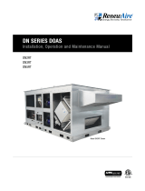
Electric Heat Module Shown
DN-Series
Integral Electric Heat Module
Supplemental Manual for Options

1.800.627.44992
Integral Electric Heat Module
OPTION
ARC FLASH AND ELECTRIC SHOCK HAZARD
Arc flash and electric shock hazard. Disconnect all electric
power supplies, verify with a voltmeter that electric power
is off and wear protective equipment per NFPA 70E before
working within electric control enclosure. Failure to comply can
cause serious injury or death.
Customer must provide earth ground to unit, per NEC, CEC and
local codes, as applicable.
Before proceeding with installation, read all instructions, veri-
fying that all the parts are included and check the nameplate to
be sure the voltage matches available utility power.
The line side of the disconnect switch contains live high-volt-
age.
The only way to ensure that there is NO voltage inside the
unit is to install and open a remote disconnect switch and
verify that power is off with a voltmeter. Refer to unit electrical
schematic.
Follow all local codes.
WARNING
RISK OF ELECTRIC SHOCK OREQUIPMENT DAMAGE
Whenever electrical wiring is connected, disconnected, or
changed, the power supply to the DOAS and its controls must
be disconnected. Lock and tag the disconnect switch or circuit
breaker to prevent accidental reconnection of electrical power.
CAUTION
RISK OF CONTACT WITH HOT SURFACES
This heater, including the heating elements, their support
structure, and surrounding DOAS components are extremenly
hot during operation. Allow sufficient time for them to cool
before working within the unit cabinet. Use extreme caution
and wear protective gloves and arm protection when working
on or near the heater.
CAUTION
RISK OF CONTACT WITH HIGH SPEED MOVING PARTS
Disconnect all local and remote power supplies, verify with
a voltmeter that electric power is off and all fan blades have
stopped rotating before working on the unit.
Do not operate this unit with any cabinet panels removed.
CAUTION
Air ducts connecting this heater to the Occupied Space
must be installed in accordance with the Standards of
the National Fire Protection Agency for the installation of
Air-Conditioning and Ventilating Systems (Pamphlet No.
90A) and Warm-Air Heating and Air-Conditioning Systems
(Pamphlet No. 90B).
IMPORTANT
This unit is intended for general ventilating and heating
only. Do not use to exhaust hazardous or explosive mate-
rials and vapors. Do not connect this equipment to range
hoods, fume hoods, or collection systems for toxics.
IMPORTANT
This equipment is to be installed by following Industry Best
Practices and all applicable codes. Any damage to com-
ponents, assemblies, subassemblies, or the cabinet which
is caused by improper installation practices will void the
warranty.
IMPORTANT

31.800.627.4499
Integral Electric Heat Module OPTION
SAVE THIS MANUAL
NOTICE
This manual contains essential information for the DOAS it is installed in. Space for main-
taining written records of heater maintenance and/or repairs is in the DOAS IOM. At the time
the DOAS is commissioned, a maintenance schedule should be developed by the user to
incorporate monthly and seasonal maintenance and include start-up maintenance tasks as
described in this manual.
UNIT INFORMATION
Record information as shown below. In the unlikely event that factory assistance is ever
required, this information will be needed.
Locate the RenewAire unit label found on the outside of the unit.
NOTE: This information is for purposes of identifying the unit-specific option data as needed,
from the option code. See DN-Series IOM Manual for further details.
Serial Number:
SO#:
Unit Option Code:
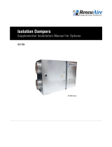
TYPICAL DN-SERIES UNIT LABEL (FOUND ON THE OUTSIDE OF THE UNIT)
TYPICAL ELECTRIC HEAT MODULE LABEL
ELECTRIC DUCT HEATER
WITH INTEGRAL LIMIT CONTROLS
Conforms to ANSI/UL STD 1996 certified to CAN/CSA STD. C22.2 No. 155
RenewAire #: EK-2416020SCCHL--43F1SS-N
FAMILY VOLTS AC PH HZ CONTROL VOLTAGE
EK 480 3 50/60 24
KW AMPS VA
19.9 23.9 12
See installation instructions for spacings, input air temperature, air velocity, etc.
T-111111
S/O:
Minimum Airflow: 70 CFM/KW (33 LPS/KW)
Minimum for this heater: 1050 CFM
Maximum Inlet Air Temp: 1000 F (37.80 C)
Maximum Outlet Air Temp: 2000 F (930 C)
C/O: Date: __/__/__
C000673182
201 Raemisch Rd . Waunakee, WI 53718 . 800.627.4499 . RenewAire.com
DUCT HEATER
E358377
LISTED
487155
ELECTRIC HEATER
PART NUMBER
UNIT
INFORMATION
D --N E
NOTE: This page
is to be completed
by the installing
contractor. The completed
document is to be turned
over to the owner after
start-up.
NOTE: Digit 17 of
the unit configura-
tion code (Option
Code) indicates that
the unit has an integral
electric heat module. For
further information on the
DOAS configuration code,
see the DN-Series Installa-
tion, Operation, and
Maintenance Manual.

1.800.627.44994
Integral Electric Heat Module
OPTION
1.0 OVERVIEW 6
1.1 DESCRIPTION .........................................................6
1.2 ELECTRICAL SUPPLY ...............................................7
1.3 HEATER CAPACITY IN KILOWATTS ...........................7
1.4 HEATER ELEMENTS ................................................7
1.5 SAFETY FEATURES .................................................8
1.5.1 Airflow Switch ....................................................................8
1.5.2 Automatic Reset Limit Switch..............................................8
1.5.3 Manual Reset Limit Switches ..............................................8
1.6 AIR FLOW ...............................................................9
1.7 MODULE HEAT RISE ................................................9
1.8 USER INTERFACE ...................................................9
1.9 ELECTRIC HEATER OPERATION ..............................10
1.10 LOW VOLTAGE CONTROL OPERATION ...................10
2.0 SYSTEM REQUIREMENTS 11
2.1 ELECTRICAL SYSTEM REQUIREMENTS ..................11
2.2 GENERAL OPERATING REQUIREMENTS ..................11
2.3 CONTROL WIRING .................................................11
2.4 LOW VOLTAGE CONTROL SYSTEM .........................11
2.5 SIZING AN ELECTRIC HEATER ................................ 12
2.6 AMPERAGE DRAW ................................................12
2.7 KW AND TEMPERATURE RISE ................................12
2.8 ELECTRIC HEATER TEMPERATURE RISE ................12
2.9 DETERMINING MAXIMUM HEATER KW ...................12
2.10 MINIMUM AIR VELOCITIES ..................................13
2.11 ELECTRICAL REQUIREMENTS ..............................14
2.12 HEATING ELEMENT WIRING CONFIGURATION .......14
2.13 DEFINITIONS FOR ELECTRIC HEAT MODULE ........15
3.0 HEATER PLACEMENT 16
3.1 GENERAL .............................................................16
3.2 DUCTWORK ..........................................................16
4.0 ELECTRICAL 16
4.1 WIRING SCHEMATICS............................................16
4.4.1 Control Panel Wiring Schematic <48A ...............................16
4.4.2 Control Panel Wiring Schematic >48A ...............................17
5.0 INSTALLATION 17
5.1 MODULE INSPECTION ON ARRIVAL ........................ 17
5.2 PREPARING FOR INSTALLATION ............................17
5.3 PLACEMENT OF MODULE ...................................... 18
5.4 CLEARANCES .......................................................19
5.5 MODULE INSTALLATION REQUIREMENTS ..............19
5.6 INSTALL SUPPLY AIR TEMPERATURE SENSOR .......19
6.0 OPERATION 20
6.1 ELECTRIC HEATER QUICK-START GUIDE ................20
6.2 VERIFY PROGRAMMING OF DOAS CONTROLLER ....20
6.2.1 Disable the Integrated Controller .......................................20
6.2.2 Disable BMS Control .........................................................20
6.2.3 Verify the Controller is Configured for Heat ........................20
6.2.4 Verify Heat Control Settings .............................................. 21
6.2.5 Verify That Heater Settings Will Call For Heat ....................22
6.3 ENABLE THE UNIT CONTROLLER ...........................22
6.4 VERIFY THE UNIT IS HEATING ................................ 22
6.5 SHUTDOWN AFTER UNIT START-UP ....................... 22
6.6 UNIT START-UP ADJUSTMENTS ............................22
6.6.1 Configuring the Controller for Normal Operation .................22
6.6.2 Normal Operation .............................................................25
7.0 MAINTENANCE 26
7.1 SERVICE PARTS .................................................... 26
8.0 TROUBLESHOOTING 27
8.1 NO HEAT ..............................................................27
8.2 INTERMITTENT HEAT ............................................28
8.3 INSUFFICIENT HEAT ..............................................29
9.0 FACTORY ASSISTANCE 30

51.800.627.4499
Integral Electric Heat Module OPTION
TABLE OF ILLUSTRATIONS
Figure 1.1.0 Electric Heater Location in DN-Series ............................................................................... 6
Figure 1.1.1 Electric Heater Oblique View .............................................................................................6
Figure 1.1.2 Electric Heater (typical) .................................................................................................... 7
Figure 1.1.3 Control Panel Cover .........................................................................................................7
Figure 1.1.4 Basic Control Panel ..........................................................................................................7
Figure 1.5.0 Heater Controls Identification ..........................................................................................8
Figure 1.7.0 Heat Rise Calculation .......................................................................................................9
Figure 2.10.0 FPM vs. KW/Ft.2 Chart ................................................................................................. 13
Figure 2.10.1 Pressure Drop Chart .................................................................................................... 14
Figure 2.10.2 Airflow Chart ............................................................................................................... 14
Figure 5.3.0 Airflow Illustration ......................................................................................................... 18
Figure 5.6.0 Duct Temperature Sensor .............................................................................................. 19
Figure 6.2.0 DOAS Controller ............................................................................................................20
Figure 7.1.0 Electric Heater Service Parts .......................................................................................... 27
TABLE OF WIRING SCHEMATICS
Figure 2.12.0 Heating Element Wiring Configuration ......................................................................... 14
Figure 4.1.0 Control Panel Wiring Schematic <48A (typical) .............................................................. 16
Figure 4.1.1 Control Panel Wiring Schematic >48A (typical) .............................................................. 17

1.800.627.44996
Integral Electric Heat Module
OPTION
1.0 OVERVIEW
1.1 DESCRIPTION
The integral electric heater used in the RenewAire DN-Series is an open-coil type heater. It
is factory-installed in the lower part of the DN-Series heat module and has its own control
panel, incorporating a disconnect switch on the control panel cover and a modulating controller
inside. Heat output is controlled by one or more Solid State Relays (SSRs). Heater operation is
controlled by the unit Integrated Programmable Controller, which provides an analog 0–10 VDC
signal. All heaters require a three phase power source which comes from the unit disconnect
switch. Multiple voltages and heater sizes are offered. A number of different control options are
selectable on the Integrated Programmable controller, to include:
u Adjustable set point, controlled by Return Air temperature
u Adjustable set point, controlled by Supply Air temperature
u OA Reset, controlled by Return Air temperature
u OA Reset, controlled by Supply Air temperature
All necessary temperature sensors are connected to the DN-Series Integrated Programmable
Controller, which interprets the sensed temperatures and then provides an analog control signal
to the heater’s control panel.
FIGURE 1.1.0 ELECTRIC HEATER LOCATION IN DN-SERIES
INTEGRAL ELECTRIC
HEATER
SA DUCT OPENING
(HORIZONTAL DISCHARGE)
HEATING ELEMENTS BEYOND
FIGURE 1.1.1 ELECTRIC HEATER OBLIQUE VIEW
NOTE: Module
covers removed for
clarity
OVERVIEW

71.800.627.4499
Integral Electric Heat Module OPTION
FIGURE 1.1.2 ELECTRIC HEATER (TYPICAL)
FIGURE 1.1.3 CONTROL PANEL COVER
FIGURE 1.1.4 BASIC CONTROL PANEL
u 5 kW
u 10 kW (9.9 actual)
u 15 kW
u 20 kW (19.9 actual)
u 25 kW
u 30 kW
u 40 kW (39.9 actual)
u 50 kW
u 60 kW (59.8 actual)
1.2 ELECTRICAL SUPPLY
The electric heat module is factory-wired and requires no additional field wiring. The electric
heat module voltage is the same as the unit voltage with a single-point connection at the unit
disconnect switch.
1.3 HEATER CAPACITY IN KILOWATTS
Electric heater capacity is based on kilowatts (kW). Electric heaters are nearly 100% efficient,
so output capacity equals input capacity. Heaters are available in the following capacities:
1.4 HEATER ELEMENTS
A choice of two different types of heater elements is offered: either 60–20–20 Ni–Cr–Fe with
nickel plated terminal pins (standard) or 80-20 Ni-Cr with stainless steel terminal pins.
OVERVIEW

1.800.627.44998
Integral Electric Heat Module
OPTION
1.5 SAFETY FEATURES
Each heater is equipped with the following:
1.5.1 Airflow Switch
The airflow switch is a non-adjustable pressure switch that prevents the heater from being
energized when no or very low air flow is present.
1.5.2 Automatic Reset Limit Switch
The auto reset limit switch is mounted on the heater next to the elements. If the limit
switch detects temperatures greater than 130˚ F [54.4˚ C], it shuts down the heater until the
temperature drops and then the limit switch automatically resets itself.
1.5.3 Manual Reset Limit Switches
There are two manual reset limit switches on the heater, located next to the heater elements.
If the limit switch detects temperatures in excess of 200˚ F [93.3˚ C], the limit switch trips and
shuts off the heater. The limit switch must be manually reset.
MANUAL RESET
LIMIT SWITCHES
AUTO RESET
LIMIT SWITCH
AIRFLOW
SWITCH
AIRFLOW SWITCH
PROBE
LIMIT SWITCHES
DISCONNECT
SWITCH
SOLID STATE
RELAY (SSR)
CONTACTORS
SIGNAL INTERFACE
MODULE (SIM)
FIGURE 1.5.0 HEATER CONTROLS IDENTIFICATION
OVERVIEW

91.800.627.4499
Integral Electric Heat Module OPTION
OVERVIEW
1.6 AIR FLOW
The air flow across the heater elements is always horizontal. If vertical discharge of the Supply
Air is chosen as part of the DN unit configuration, the air flow is directed downward through
the floor of the unit, after it passes through the electric heater. A minimum airflow through
the heater is required at all times in order for the heater to operate. See Section 1.5.1 Airflow
Switch.
1.7 MODULE HEAT RISE
All modules are installed on the positive pressure side of the fan.
u Maximum allowable discharge temperature is 120˚ F [48.9˚ C] for any installation.
u Maximum allowable temperature rise is 90˚ F [50˚ C].
u Maximum design duct static pressure is 3.0 InWC .
Note that the example below is based upon a specific Entering Air temperature. As Entering Air
temperatures vary, the resulting temperature rise will also vary.
FIGURE 1.7.0 HEAT RISE CALCULATION
3000 CFM
45 ˚F Entering
Air Temp
30 kW
Input
31.5 ˚ F Rise
76 ˚F
Discharge
Air Temp
1.8 USER INTERFACE
The User Interface (U/I) is the device used to control operation of the module. This module is an
integral part of a DN unit and is therefore controlled by the on-board Integrated Programmable
Control.

1.800.627.449910
Integral Electric Heat Module
OPTION
1.9 ELECTRIC HEATER OPERATION
The electric heat module modulates its heat output by applying controlled, high-voltage pulses
of current to the heating elements. High-voltage power comes from the heater disconnect
switch and goes through one or two sets of contactors before being applied to a Solid State
Relay (SSR). In normal operation, high voltage power is always present at the SSR, as long
as the contactors are energized by the presence of 24 VAC. The SSR is controlled by a device
called a Burst Firing Control Module (BFCM) that is mounted on the SSR.
The BFCM is a device that interprets a 0 – 10 VDC call for heat signal from the unit controller.
Depending on the voltage of the call for heat signal, the BFCM will switch the SSR ON and OFF
in high-speed pulses, causing the heat output to satisfy the call for heat.
In some larger electric heat modules (greater than 48A), the BFCM is replaced by a Vernier Step
Controller, mounted on its own circuit board. The step controller is used to prevent extremely
high-amperage surges by bringing on stages as needed.
The heater receives a 0-10 VDC activating signal from the Integrated Programmable Controller.
The activating control signal comes into the heater control box and is terminated on the Signal
Interface Module (SIM) or terminal strip. From there, the signal is applied to the BFCM, which
is mounted on the SSR. The signal applied to the BFCM causes the SSR to generate a series of
high-voltage pulses, applied to the heater elements. The higher the control signal voltage, the
more high-voltage pulses that are applied to the heater elements.
Heater operation and output is controlled by the unit Integrated Programmable Controller,
based on desired temperature. The heater shuts off when the controller senses that the desired
temperature condition is met.
The heater will switch off if insufficient airflow is detected. The heater will also switch off if an
over-temperature condition occurs. This condition is identified by intermittent or no heating. If
this occurs, the cause of the over-temperature condition should be identified and corrected.
Also see Section 1.10 Low Voltage Control Operation.
1.10 LOW VOLTAGE CONTROL OPERATION
The low voltage control circuitry consists of:
u 24 VAC transformer
u Signal Interface Module (SIM), or terminal block.
u Contactors with low-voltage coils. NOTE: There are often back-up contactors whose coils
operate on line voltage.
u SSR Burst Firing Control Module (BFCM) (mounted directly on each SSR and not shown as a
separate component on wiring schematic).
u Auto-reset high temperature switches. NOTE: There is also a manual-reset high temperature
switch that operates on line voltage, not 24 VAC.
u Air flow switch
From the secondary side of the transformer, 24 VAC is supplied to the devices in the low voltage
control circuit.
The signal interface module (SIM) or terminal strip receives the 0–10 VDC control signal from
the DOAS controller. The control signal then goes to either the BFCM or to a Vernier Step
Controller.
Contactors with low-voltage coils require 24 VAC to operate. Contactors are used primarily as
safety devices that can interrupt current flow to the SSR in case of over-temperature or lack
of air flow. In addition to a low-voltage contactor, there may be a backup contactor that is
switched ON/OFF by line voltage.
NOTE: The
electric heat module
uses a Solid State
Relay (SSR) to modulate
heat output. Modulation
provides a more efficient
method of heating the
Occupied Space than
running at full output for
brief periods.
NOTE: The term
“Solid State Relay”
(SSR), is a
generic control
type. The term “Silicon
Controlled Rectifier” (SCR)
is a specific type of SSR.
The two terms are often
interchanged and both are
correct. For consistency,
ther term “SSR” is used in
this manual.
NOTE: A contactor
is an electronical-
ly-controlled switch
used for switching
an electrical power circuit
ON and OFF. Contactors
are controlled by a second
circuit that is usually 24
VAC (low voltage). In some
cases, the secondary
circuit may be the same as
the line voltage (high volt-
age). All contactors used in
electric heat modules are
Normally Open (NO) and
require activating voltage
in order to close.
OVERVIEW

111.800.627.4499
Integral Electric Heat Module OPTION
The BFCM interprets the controller 0–10 VDC input signal and then supplies timed pulses of
power to the Solid State Relay (SSR), which applies high-voltage power to the heater elements.
On small electric heat modules, the BFCM is attached directly to the SSRs. On heat modules
larger than 48A, a Vernier Step Controller is mounted on a separate board.
Auto-reset high temperature switches and the air flow sensor module are connected in series
between 24 VAC and ground. If a high temperature reset switch is tripped open or if the air flow
switch does not sense adequate air movement in the heater, the circuit is opened and the low-
voltage contactors will not operate. Line voltage will not be supplied to the SSR.
Also, see Section 1.9 Electric Heater Operation and Section 2.4 Wiring Schematics in this
manual.
2.0 SYSTEM REQUIREMENTS
2.1 ELECTRICAL SYSTEM REQUIREMENTS
The electric heater is factory-wired and requires no additional field wiring. The unit nameplate
label displays the unit and electric heater voltage.
2.2 GENERAL OPERATING REQUIREMENTS
Minimum Air Velocity: 70 CFM per KW (75-80 Recommended)
Maximum Inlet Air Temp: 100˚ F [37.8˚ C]
Maximum Heater KW: 30 kW per square foot of heater cross section.
The velocity of air should NEVER be lower than the specified minimum. In cases where this is
not true, the kW must be reduced or the velocity of air increased.
2.3 CONTROL WIRING
NOTE: SSRs operate
on line voltage but
their output is
controlled by the low-volt-
age BFCM.
NOTE: Minimum
air flow or greater
must be maintained
uniformly over the entire
face of the heater.
NOTE: Observe at
least one Heating
cycle to ensure that
cycling of safety
limit controls does not oc-
cur under normal operating
conditions before leaving
the installation.
NOTE: The air tem-
perature entering
the heater should
not exceed that
marked on the heater
nameplate label.
SYSTEM REQUIREMENTS
DO NOT adjust any dip switches on the controls within the heater! The dip switches are
factory-set and are not to be changed.
IMPORTANT
The electric heat module receives its control signals from the DN-Series Integrated
Programmable Controller. In the event that a Building Management System (BMS) is controlling
the DOAS, BMS wiring is to be connected to the Integrated Programmable Controller, in
accordance with DOAS instructions.
2.4 LOW VOLTAGE CONTROL SYSTEM
This heater is provided with a Class II 24 VAC power supply system that operates the heater’s
contactor(s). In the event of a short-circuit or overload, the transformer itself is designed to fail
safely.
Do not use the electric heat module transformer to power external controls. Use the DOAS
low-voltage 24 VAC transformer or an external, field-supplied 24 VAC transformer.
If external controls are powered by the DOAS low-voltage 24 VAC transformer or a field-sup-
plied external 24 VAC transformer, follow the requirements for those transformers regarding
wire length, wire gauge, and power draw.
IMPORTANT

1.800.627.449912
Integral Electric Heat Module
OPTION
2.5 SIZING AN ELECTRIC HEATER
An electric heater can be sized from the following information:
u Heater Width (W") and Heater Height (H")
DN-2 = 16" H X 24" W
DN-3 = 16" H X 30" W
DN-5 = 16" H X 30" W
u Heater voltage and phase
u Heater Capacity rating (kW)
u Or Design Air Flow (CFM) and
u Desired Temperature Rise (∆˚F)
2.6 AMPERAGE DRAW
The formula for calculating line current is:
(Three phase): Amps = Watts / (line voltage of heater X 1.73)
To convert kW to Watts, multiply kW by 1,000.
2.7 KW AND TEMPERATURE RISE
The following formula may be used to determine the approximate total kW required when the
CFM (air volume) and desired temperature rise are known:
kW = CFM X ∆T
3150
2.8 ELECTRIC HEATER TEMPERATURE RISE
Temperature rise is expressed as ∆T. The following formula may be used to determine the
approximate temperature rise of an electric heater when the kW and CFM are known:
kW X 3150
CFM
2.9 DETERMINING MAXIMUM HEATER KW
Maximum watts per square inch of heater area:
Heater width (inches) x heater height (inches) = Heater Area total square inches.
Max watts = 208.33 ( ) x Heater area in2
Maximum kW for square foot of heater area:
Heater width (feet) X heater height (feet) = heater area total ft2.
Max kW = 30 ( ) x Heater area ft2
kW
∆T =
in2
W
ft2
SYSTEM REQUIREMENTS

131.800.627.4499
Integral Electric Heat Module OPTION
2.10 MINIMUM AIR VELOCITIES
The minimum uniform airflow in the integral electric heater is directly related to the inlet
air temperature. Consideration must be given to both airflow across the heater and inlet air
temperature, see the Minimum Air Velocities chart below.
1. Calculate the kilowatts per square foot of heater area by dividing the total kW required by the
heater area.
Example: Total kW = 20
Heater area = (24" x 16") / 144 in2 = 2.67 ft2
kW / ft2 = 20 = 7.49 kW / ft2
2.67
2. If the air flow is expressed in FPM then a direct cross reference can be made by comparing
the temperature of the air (as it enters the electric heater) to the kW rating on the chart of
rated velocity.
u Draw a line horizontally from the kW/Sq. Ft. required to the air inlet temperature being used
u From the point of intersection on the Inlet Air Curve, draw a line down vertically to establish
the air velocity.
u The velocity should never be lower than the velocity as determined from the chart. In cases
where this is not true, the velocity must be increased or the kW required must be reduced.
3. In cases where the air flow is expressed in CFM, then convert to FPM by dividing the CFM by
the heater area.
Example: FPM = CFM
Heater Area
NOTE: Minimum
airflow must be
maintained at all
points over the face of the
heater.
SYSTEM REQUIREMENTS
MINIMUM AIR VELOCITIES
FIGURE 2.10.0 FPM VS. KW / FT.2 CHART

1.800.627.449914
Integral Electric Heat Module
OPTION
0
0.02
0.04
0.06
0.08
0.1
0.12
0.14
0.16
0.18
02004006008001000120014001600180020002200
PRESSURE DROP THROUGH HEATER
Static Pressure Drop - Inches of Water
Air Velocity - FPM (1, 2, 3 and 4 - the number of rows of heater coils)
When the number of rows of heater coils is unknown, assume 4. 0
10
20
30
40
50
60
70
0500 1000 1500 2000 2500 3000 3500 4000 4500 5000
HEATER CAPACITY -kW
AIRFLOW -CFM
Electric Heater Capacity
FIGURE 2.10.1 PRESSURE DROP CHART FIGURE 2.10.2 AIRFLOW CHART
SAFE
OPERATING
RANGE
1
2
3
4
SYSTEM REQUIREMENTS
2.11 ELECTRICAL REQUIREMENTS
Refer to general wiring diagram in Section 4.0 of this manual. Each heater also has its own
specific wiring schematic label on the inside cover of the heater control box.
2.12 HEATING ELEMENT WIRING CONFIGURATION
THREE WIRE DELTA CONNECTION
1. Element Voltage = Line Voltage
2. Phase Currents In = lL1 = lL2 = lL3
3. Voltage measured between any two
power legs (L1 to L2 etc.) should be
equal to the three phase line voltage.
THREE WIRE WYE CONNECTION
1. Element Voltage = Line Voltage
1.73
2. Phase Currents In = lL1 = lL2 = lL3
3. Voltage measured between any two
power legs (L1 to L2 etc.) should be
equal to the three phase line voltage.
THREE PHASE
480V for illustration only
lL1
lL3
lL2
L1
480 V
480V
480 V
L2
L3
lL1
lL3
lL2
480 V
480 V
480 V
L1
L2
L3
FIGURE 2.12.0 HEATING ELEMENT WIRING CONFIGURATION

151.800.627.4499
Integral Electric Heat Module OPTION
2.13 DEFINITIONS FOR ELECTRIC HEAT MODULE
Heater Type:
EK—Electric heater module
Width:
W—Width of electric heating element in inches.
Range 24", 30"
Height:
H—Height of electric heating element in inches.
Range 16"
Capacity:
KW—Kilowatt rating of heater. Determined by airflow
(CFM) and temperature rise (∆T).
Range 5, 10, 15, 20, 25, 30, 40, 50, 60
Mount:
Slip-in (Standard)—heater is installed through opening in
unit vestibule
Element Style:
Open Coil (Standard)—open coil resistance wire.
Element Material:
60-20-20 NI-CR-FE with nickel plate terminal pins
(Standard)-standard “C” grade element wire. 60% nickel,
20% chromium, 20% iron.
80-20 NI-CR with stainless steel terminal pins (Option)-
premium “A” grade element wire. 80% nickel, 20%
chromium.
Airflow Orientation:
Horizontal (Standard)—heater installed where airflow is
horizontal through the heater.
Control Box Offset:
Left Hand (Standard)—the control panel is offset to the
left side of the heating elements as determined when
looking into the control box.
Vertical—the control panel is aligned vertically with the
heating elements as determined when looking into the
control box. Only available on DN-2.
Voltage and Phase:
3-Phase-208 V, 240 V, 480 V, 600 V
Power Fusing:
Standard on all electric heater modules.
Stage:
Single Stage (Standard)—All heating elements are
energized simultaneously. Selected when heater
amperage is less than 96 A.
4-Stage—Heating capacity is divided into four sections.
Selected when heater amperage is greater than or equal
to 96 A.
Control Voltage:
24 VAC (Standard)—secondary voltage
Control Type:
Silicon Controlled Rectifier (SCR)—100% step-less
modulating control. Accepts 0–10 Vdc from DOAS unit
controller. Utilizes solid state relays (SSR) to switch
current to the heating elements, on a time-proportioned
basis.
An SSR is an electronic switching device similar to an
electromechanical relay (contactor) but has no moving
parts which allows very fast switching of high current
loads without arcing or wearing out. A heater with an SSR
controller must be installed in such a way as to provide
good ventilation to the heat sink so that the life of the SSR
is prolonged. Over-heating of an SSR causes it to fail.
Airflow Switch: (Standard)
Non-adjustable pressure switch that prevents the heater
from being energized when no or very low air flow is
present through the heater. Minimum air flow pressure is
0.05 InWG +/- .02.
Auto Reset: (Standard)
Automatic reset limit switch for primary over-temperature
protection. Required by UL.
Manual Reset: (Standard)
Manual reset limit switch for secondary over-temperature
protection. Required by UL.
Disconnect Switch: (Standard)
Non-fused interlocking switch mounted in the door of the
heater control box. Must be turned off to open door on
control box. Interrupts power to the heater when turned
off.
Ground Lug: (Standard)
Connection point for grounding line voltage.
u All heaters are designed for zero clearance.
u Control box is constructed of galvanized steel.
u Control box has hinged access door with interlocking
disconnect switch.
u All heaters are UL and cUL recognized components.
SYSTEM REQUIREMENTS

1.800.627.449916
Integral Electric Heat Module
OPTION
FIGURE 4.1.0 CONTROL PANEL WIRING SCHEMATIC <48A (TYPICAL)
NOTE: Some compo-
nents shown on this
typical schematic
may not be present on the
unit as shipped from the
factory. See the electric
heater wiring schematic on
the inside of the electric
heat panel door in the unit
heat module for specific
wiring.
3.0 HEATER PLACEMENT
3.1 GENERAL
All electric heat modules are installed on the positive side of the circulating blower. Modules
must be installed in a level, horizontal position. Observe unit clearances as shown in Section
5.4.
This information and these instructions apply to electric heater models for zero clearance
installation.
u The electric heaters are approved for use with heat pumps, air conditioners or other forced
air systems.
u The electric heaters are pre-wired and have voltage ratings to 600 volts, three phase.
u The electric heaters are furnished with integral controls.
3.2 DUCTWORK
Ductwork shall be sized to fit the openings of the heat module. Uniform airflow distribution over
the electric heater elements is essential for proper operation and optimum efficiency. Use of
baffles and/or turning vanes may be required to provide uniform airflow. Ductwork is fastened
directly to the unit cabinet and then sealed, using Industry Best Practices/SMACNA guidelines.
4.0 ELECTRICAL
4.1 WIRING SCHEMATICS
4.1.1 Control Panel Wiring Schematic <48A
HEATER PLACEMENT

171.800.627.4499
Integral Electric Heat Module OPTION
4.1.2 Control Panel Wiring Schematic >48A
FIGURE 4.1.1 CONTROL PANEL WIRING SCHEMATIC >48A (TYPICAL)
NOTE: Some compo-
nents shown on this
typical schematic
may not be present on the
unit as shipped from the
factory. See the electric
heater wiring schematic on
the inside of the electric
heat panel door in the unit
heat module for specific
wiring.
5.0 INSTALLATION
Electric heaters are completely installed in the factory and meet code and application
requirements.
5.1 MODULE INSPECTION ON ARRIVAL
As part of the DOAS inspection on arrival, the following areas of concern should be inspected:
u All screw-down electrical connections should be inspected for tightness.
u Visually inspect the heater elements to make sure that none are broken loose.
5.2 PREPARING FOR INSTALLATION
The electrical ratings for the module and unit are shown on the unit data plate found on the
outside of the unit. Before installation, verify that the electrical supply matches the data plate
information. Read this manual in its entirety before beginning installation. Check with local
agencies having jurisdiction for any local requirements.
ELECTRICAL

1.800.627.449918
Integral Electric Heat Module
OPTION
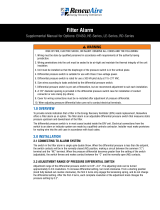
5.3 PLACEMENT OF MODULE
Because the DOAS may be incorporated into an owner’s existing HVAC system, the following
application principles should be observed:
1. Never operate an electric heater without airflow. The heater must always be interlocked with
the fan. This is accomplished with an airflow switch and fan interlock through unit controller.
2. Never operate heater without achieving at least the minimum airflow required. Always refer
to the installation instructions and the nameplate label to determine your minimum air
velocities based on your inlet air temperature. If the minimum airflow requirements are not
present the heater will not function properly and safely (see Airflow Illustration below).
3. Never operate the heater with uneven airflow. The minimum airflow requirements must be
present at all points over the heater face.
4. Always locate the heater (unit SA opening) at least 24" from an elbow or turn.
5. Always locate the heater (unit SA opening) at least 48" from a heat pump or central air
conditioner.
6. Always locate the heater (unit SA opening) at least 48" from any canvas duct connector or
transition section for change in duct size. Use round-to-rectangular pyramidal transitions
to connect round duct to rectangular duct. Always locate the heater at least 48" from any
transition section for change in duct size. Follow installation guidelines given in manual and
in accordance with SMACNA guidelines.
7. Always locate the heater (unit SA opening) at least 48" upstream from an humidifier.
8. Never insulate the exterior of the control box. The control box must be completely accessible
and located where ventilation can be provided at all times.
9. Never use a different voltage and/or phase than what is listed on the heater nameplate label.
The electric heater is to be used only at the voltage and phase that is listed on the nameplate
label.
500 fpm
470 fpm
780 fpm
ELECTRIC DUCT HEATER
TROUBLESHOOTING GUIDE
24" MIN.
48" MIN.
HEAT PUMP OR
AIR CONDITIONER
HEATER
HEATER
DUCT
DUCT
HEATER
48" MIN. 48" MIN.
HEATER
EXAMPLE: IF 780 fpm IS REQUIRED
EXAMPLE: IF 780 fpm IS REQUIRED
EXAMPLE: IF 780 fpm IS REQUIRED
CORRECT
MIN. AIRFLOW AND EVEN AIR
DISTRIBUTION ARE PRESENT
INCORRECT
MIN. AIRFLOW AND EVEN AIR
DISTRIBUTION ARE NOT PRESENT
INCORRECT
MIN. AIRFLOW IS NOT PRESENT
INCORRECT
CORRECT
FIG. 1
FIG. 2
FIG. 3
FIG. 4
A DUCT HEATER MUST BE INSTALLED ACCORDING
TO THE INSTALLATION INSTRUCTIONS, WIRING
DIAGRAM AND LABELING SUPPLIED WITH THE
HEATER.
Listed below are some important items when installing
a electric duct heater:
1. NEVER OPERATE A DUCT HEATER WITHOUT
AIRFLOW.
The heater must always be interlocked with the
fan. This may be accomplished by either an airflow
switch or fan interlock relay.
2. NEVER OPERATE HEATER WITHOUT ACHIEVING
AT LEAST THE MINIMUM AIRFLOW REQUIRED.
Always refer to the installation instructions and
the nameplate label to determine your minimum
air velocities based on your inlet air temperature.
If the minimum airflow requirements are not
present the heater will not function properly and
safely. (see fig. 1)
3. NEVER OPERATE THE HEATER WITH UNEVEN
AIRFLOW.
The minimum airflow requirements must be
present at all points over the heater face.
(see fig. 1)
4. THE AIR MUST BE FILTERED.
The incoming air must be free from all debris,
combustible particles, and hazardous vapors.
5. ALWAYS LOCATE THE HEATER AT LEAST 24"
FROM AN ELBOW OR TURN.
(see fig. 2)
6. ALWAYS LOCATE THE HEATER AT LEAST 48"
FROM AN HEAT PUMP OR CENTRAL AIR
CONDITIONER.
(see fig. 3)
7. ALWAYS LOCATE THE HEATER AT LEAST 48"
FROM ANY CANVAS DUCT CONNECTOR OR
TRANSITION SECTION FOR CHANGE IN DUCT
SIZE.
(see fig. 4)
8. ALWAYS LOCATE THE HEATER AT LEAST 48"
DOWNSTREAM FROM AN AIR HANDLER.
(see fig. 5)
9. ALWAYS LOCATE THE HEATER AT LEAST 48"
UPSTREAM FROM AN HUMIDIFIER.
(see fig. 6)
470 fpm
470 fpm
780 fpm
780 fpm
DUCT
DUCT
PAGE 1 OF 2
NOTE: ALL FIGURES ARE SHOWING A TOP
VIEW OF A HORZONTIAL DUCT.
780 fpm
780 fpm
500 GOULD DRIVE COOKEVILLE, TN 38506
FAX (931)432-4140 PHONE (931)432-4141
INC.
FIGURE 5.3.0 AIRFLOW ILLUSTRATION
NOTE: An airflow
switch only proves
that airflow exists
(a differential in static
pressure), not that the
minimum air velocities and
proper air distribution for
the heater exist.
INSTALLATION

191.800.627.4499
Integral Electric Heat Module OPTION
5.4 CLEARANCES
Clearances are as detailed on the Dimensioned Drawing of each unit type, as applicable.
Dimensioned drawings are found in the DN-Series IOM.
Sufficient space must be left in front of the DOAS to allow for servicing of the unit and its
electric heater module. See the dimensioned drawing for each model, as applicable.
5.5 MODULE INSTALLATION REQUIREMENTS
The heat module is installed on the positive pressure side of the unit fan. The air throughput
must be within the CFM range marked on the module rating plate.
Ductwork should be mechanically fastened to the unit. Joints should be sealed with high
temperature silicone caulking or high temperature tape to prevent leakage of circulating air. All
outdoor module connections must be weather-tight to prevent rain and snow from entering the
ductwork. Support all ductwork securely. DO NOT rely solely on module duct connections for
support.
5.6 INSTALL SUPPLY AIR TEMPERATURE SENSOR
The Supply Air temperature sensor is factory-wired to the Integrated Programmable Controller
but the sensor must be installed in the SA ductwork downstream of the electric heat module.
The temperature sensor should be installed between 4 and 6 feet from the unit in the SA
ductwork to control the temperature output of the electric heat module. The Supply Air
temperature sensor is shipped in the low-voltage side of the unit electrical box (E-box).
Provide adequate service access for maintenance. The module requires regular inspections.
Install the module where access panels can be removed for cleaning and inspection and
wiring can be accessed for installation and service. Observe all safety precautions when
working on roofs, including locating the unit away from roof edges, provision of safety rail-
ings, and use of fall-protection equipment
IMPORTANT
FIGURE 5.6.0 DUCT TEMPERATURE SENSOR
RISK OF OVERHEATING
Do not install, place, or store materials within the DN unit in front of the electric heater.
CAUTION
INSTALLATION

1.800.627.449920
Integral Electric Heat Module
OPTION
6.0 OPERATION
6.1 ELECTRIC HEATER QUICK-START GUIDE
Operation of the electric heater module is dependent on receiving high voltage power from the
DOAS disconnect switch and a 0-10 VDC control signal from the DN Integrated Programmable
Controller. Refer to the DN Integrated Controls User Manual for detailed instructions.
Turn ON the electric heater disconnect switch.
6.2 VERIFY PROGRAMMING OF DOAS CONTROLLER
6.2.1 Disable the Integrated Controller
Turn ON the unit disconnect switch. As soon as the disconnect switch is turned ON, the
controller will begin to boot-up, which takes about 10 seconds. When the Home Screen is
displayed, press the ESCAPE button to go to the Main Menu. Scroll down to Unit Enable and
press ENTER. Verify that the screen shows “OFF”. This will prevent the electric heat module
from trying to run prematurely. Press the ESCAPE button to exit without changing the status.
6.2.2 Disable BMS Control
For purposes of testing operation of the electric heater module, BMS control of the heater
should be left turned OFF. On the controller, go to Home Screen > Main Menu > Settings and
then press ENTER on the controller. For operation of the DOAS without BMS control, the screen
should say ENABLE BMS: NO. Exit this menu item by pressing the ESCAPE button.
6.2.3 Verify the Controller is Configured for Heat
Go to Home Screen > Service Menu > Unit Type. Press the ENTER button. The next screen is
the hardware configuration screen. Verify that ENABLE HEAT is YES. Exit this menu item by
pressing the ESCAPE button.
UP ARROW BUTTON
ENTER BUTTON
DOWN ARROW BUTTON
ESCAPE BUTTON
DISPLAY SCREEN
ALARM BUTTON
PROGRAM BUTTON
FIGURE 6.2.0 DOAS CONTROLLER
NOTE: Start-up and
testing of the inte-
gral electric heater
is normally done after
the DN-Series Integrated
Programmable Controller
has been configured. The
steps show in Section 6 of
this manual are to con-
firm that the controller is
programmed to operate in
a test mode.
NOTE: Minimum
aiflow through the
electric heat module
must be maintained at all
times during operation.
NOTE: Observe at
least one complete
heating cycle to
verify proper operation of
the electric heat module.
This may require further
adjustment of the heating
setpoint.
NOTE: For further
information on how
to navigate the con-
troller, see the DN
Integrated Controls User
Manual.
OPERATION
Page is loading ...
Page is loading ...
Page is loading ...
Page is loading ...
Page is loading ...
Page is loading ...
Page is loading ...
Page is loading ...
Page is loading ...
Page is loading ...
Page is loading ...
Page is loading ...
/