Honeywell Home HE360 Owner's manual
- Category
- Dehumidifiers
- Type
- Owner's manual
This manual is also suitable for

OWNER’S MANUAL
69-2631ES-13
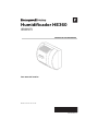
HE360 Humidifier
HE360A1075
HE360D1075
Read before installing
Input: 120 Vac, 60 Hz, 0.7A

HE360 HUMIDIFIER
69-2631ES—13 2
WELCOME
To the comfortable world of humidified air. When you use your Resideo humidifier, notice that your skin is not as
dry, and that your scratchy throat and irritated nasal passages that aggravate allergies and asthma are steadily
improving.
You have also taken the first step in reducing the zapping you create when you walk on your carpet and then
touch your TV, computer, metal door knob or your pet. Your furniture and woodwork are also benefiting from the
difference that humidified air makes.
Congratulations! You have just made a great investment in improving the comfort of your home.
INSTALLATION
Preparing for the Installation
Be sure to identify all the included accessories (Table 1) and make sure the appropriate tools and accessories
are available before beginning the installation.
Suggested Tools and Accessories
Tools required for installation include:
• Tin snip.
•Screwdriver.
• Adjustable or open-end wrench.
• Drill, punch or awl.
• Level.
• 18 gauge, two-strand thermostat wire.
• 1/4 in. (6.35 mm) OD feed water tubing.
• 1/2 in (12.7 mm) ID drain tubing.
• Code-compliant 1/4" water shut-off valve and fittings.
Included Accessories
Table 1. Included Accessories.
Quantity Accessory
1 bag Connecting and mounting hardware:
Wire nuts (4)
No. 8 sheet metal screws (18)
Drain tube clamp
Feed tube mounting clamps (6)
Brass inserts (2)
Plastic compression rings (2)
1Pressure switch
1 H6062 Humidistat

HE360 HUMIDIFIER
3 69-2631ES—13
Determining Best Location for Humidifier
CAUTION
Temperature and Static Pressure Hazard.
Can cause property or equipment damage.
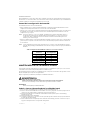
Locate humidifier where ambient temperature is between 32°F (0°C) and 160°F (71°C).
Do not install humidifier where freezing temperatures could occur.
Be sure supply plenum static pressure is no greater than 0.4 in. wc and water pressure is no greater than
124 psi.
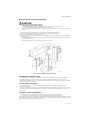
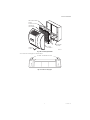
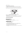
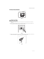
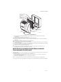
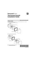
• Select a location for the humidifier on the supply (warm air stream) plenum. See Fig. 1.
• Select a location that cannot damage the air conditioner A-coil during installation.
• Do not locate the humidifier on the furnace body.
• Allow adequate clearance in front of and above the humidifier so you can easily remove the cover to perform
routine maintenance.
— Mount the humidifier at least 3 in. (78 mm) above the furnace body to allow adequate space for the sole-
noid valve and drain line.
— Mount the humidifier in a conditioned space to prevent freezing.
Fig. 1. Typical humidifier installation locations.
Selecting Water Supply Location
• Use either hard or soft water in the humidifier and either hot or cold water. The water flow rate, with the
humidifier running, is 3.5 gal/hr (13 liters/hr) to flush the pad and provide moisture for evaporation.
• Make sure the length of the 1/4” of feed water tubing is adequate to connect the water supply shut-off valve
with the humidifier solenoid valve.
Locating Closest Floor Drain
• Select location with access to a floor drain to provide drainage for air conditioner condensation and
humidifier drainage.
• If you do not have a drain available, we recommend that you install the Resideo Whole House Drum or Disk
Humidifier. Make sure that the drain tubing is adequate to reach from the humidifier drain connection to the
floor drain.
Selecting Location for Humidistat
• Select a location for the humidistat on the return plenum or on the wall in the living space.
— Mounting on the return plenum is the easiest installation for the control wiring circuit.
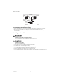
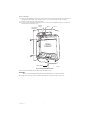
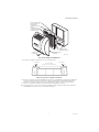
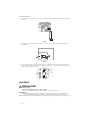
For return duct mounting, the humidistat should be mounted upstream from the humidifier or bypass so that it
is properly sensing the relative humidity of the living space. Locate the control at least 8 in. (203 mm) upstream
from the humidifier in the return air duct. (See Fig 2.)
M12808C
HORIZONTAL
DOWN
FLO
LOWBOY
RETURN
RETURN
RETURN
HIGHBOY
RETURN

HE360 HUMIDIFIER
69-2631ES—13 4
Fig. 2. Selecting duct location for humidistat.
Locating Closest 120 V Electrical Outlet
• Select location with access to an outlet. If not available, contact an electrician to have one installed.
• Make sure that the humidifier cord is adequate to reach from the humidifier to the outlet.
• Make sure that the thermostat wire is adequate to reach from the humidifier solenoid, to the pressure switch,
to the humidistat.
Installing the Humidifier
WARNING
Hazardous Voltage
Can cause personal injury or equipment damage.
Do not cut or drill into any air conditioning or electrical accessory.
CAUTION
Sharp Edges Installation Hazard.
Can cause personal injury.
Wear gloves and safety glasses.
1. Turn off power to the air handing system at the circuit breaker.
2. Draw a level line on the plenum in the location
chosen for the humidifier. (Leveling assures optimal humidifier performance.)
3. Locate the template (form number 69-2641 included in the box).
4. Tape the template in position and trace around the template.
5. Remove the template and carefully cut the rectangular opening.
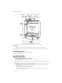
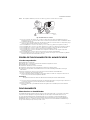
6. Disassemble the humidifier; remove the cover and take out the humidifier pad assembly. See Fig. 3.
ALTERNATE
LOCATION
RETURN
AIR RETURN
AIR
6 IN (152 MM)
MINIMUM
15 IN (381 MM)
MINIMUM
BEST
LOCATION
RETURN
AIR DUCT
M34579B

HE360 HUMIDIFIER
5 69-2631ES—13
Fig. 3. Disassembling humidifier.
7. Position the securing clips as shown in Fig. 4.
Fig. 4. Position securing clips.
M12809A
COVER
ASSEMBLY
HUMIDIFIER
PAD ASSEMBLY
FEED TUBE NOZZLE
WATER
DISTRIBUTION TRAY
HUMIDIFIER
HOUSING
THUMB
SCREW
M12813B
CLIP CLIP
TOP VIEW – HUMIDIFIER HOUSING

HE360 HUMIDIFIER
69-2631ES—13 6
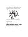
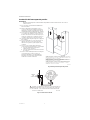
8. Make sure the humidifier housing is level, then position it in the opening so the plastic tabs are in place on
the upper sheet metal edge of the opening. Use pliers, as necessary, to flatten cut edges. See Fig. 5.
9. Push in securing clips until completely seated.
10. Drill holes and install the three sheet metal screws on the top of the humidifier housing. Secure the hous-
ing with the three remaining screws.
Fig. 5. Installing humidifier on duct.
11. Reinstall the humidifier pad assembly in the humidifier housing.
IMPORTANT
Be sure to reconnect the water feed tube and ensure that the tube is not pinched or kinked.
12. Hinge the cover in place and secure with the thumbscrew located at the bottom of the cover.
DUCT
LEVEL
SHEET METAL
SCREWS (4)
PLASTIC
TABS (2)
DRAIN TUBING
M20204C
OPENING
TO AIR DUCT

HE360 HUMIDIFIER
7 69-2631ES—13
Connecting the Plumbing
Use hot or cold water and either hard or softened water in the humidifier.
1. Shut off the water.
CAUTION
Chemical Hazard.
Can cause personal injury or equipment damage.
Do not use any line connected to an air conditioner.
Do not use gas line.
2. Install the water shut-off valve in the water sup-
ply line at the location selected per local code.
3. Use 1/4 in. (6 mm) copper or OD tubing and
connect the shut-off valve to the inlet side of the
solenoid valve on the humidifier.
a. Insert the tubing into the solenoid valve fit-
ting and support the valve while tightening
the compression nut.
b. Place the brass compression nut over the
tubing.
c. Install brass insert into end of tubing.
d. Slide the plastic compression ring over the
tubing. (Discard copper compression ring
provided with valve.)
NOTE: To prevent leaking, use plastic (Delrin) sleeve
rings with plastic tubing. Use copper sleeve
rings only with copper tubing.
NOTE: Do not over-tighten the compression nut.
Moderate tightness prevents leaking.
e. Secure tubing with clamps provided.
Fig. 6. Installing feed tubing.
4. Connect a 1/2 in. (13 mm) drain tube to the
humidifier drain fitting and run to the floor drain
(see Fig. 7).
a. Slide the drain clamp over the tubing.
b. Push the tubing over the drain nipple on the
humidifier.
c. Tighten the clamp around the tubing using a
pliers/hand to secure the humidifier drain.
d. Fasten the drain tubing (can use duct tape)
along the route to prevent movement and
ensure downward slope for correct drainage.
NOTE: Cut tubing to correct length so the tubing ter-
minates at the drain.
Fig. 7. Installing the drain tubing.
M39203
BRASS COMPRESSION NUT
PLASTIC
COMPRESSION
RING
BRASS INSERT
SOLENOID
VALVE
M20177A

HE360 HUMIDIFIER
69-2631ES—13 8
Installing the Pressure Switch
IMPORTANT
Do not install the switch in an area where temperature exceeds rating of
-40°F to 190°F (-40°C to 88°C).
1. Disconnect power from the humidifier before
installing.
2. Mount the switch vertically with pressure
connectors facing down, using provided self-
tapping screws to secure the switch to the duct.
3. Cut 3/4-in. (19 mm) diameter holes in the
supply and return ducts within 10 feet of the
switch to ensure the provided tubing reaches the
pressure tap elbows. See Fig. 8.
4. Insert the black rubber gaskets into the duct
holes.
5. Connect the tubing to the tubing fitting elbows
and insert the tubing fitting elbows into the
black rubber gaskets in each duct.
6. Connect the other end of the tubing to the
applicable pressure connection on the switch.
a. Connect supply duct tubing to the +
connection.
b. Connect return duct tubing to the –
connection
7. You may cut the tubing to fit the connection
length between the elbow fitting and switch. It is
also recommended to secure the hose to
existing structures to avoid accidental
disconnection.
Fig. 8. Mounting the pressure switch.
Fig. 9. Install tubing.
M27303A
A
B
SUPPLY DUCT INSTALL - AIR LINE ONLY TO TAP A,
CONNECTED TO THE + PORT ON THE AIR FLOW SWITCH
RETURN DUCT INSTALL - AIR LINE ONLY TO TAP B,
CONNECTED TO THE – PORT ON THE AIR FLOW SWITCH
SUPPLY/RETURN DUCT INSTALL - AIR LINE CONNECTED
TO BOTH THE + AND – PORTS ON THE AIR FLOW SWITCH
M27304A
INSIDE
OF DUCT
CONNECT TUBING TO + CONNECTION IF PRESSURE TAP IS
MOUNTED TO SUPPLY DUCT. CONNECT TO – IF PRESSURE
TAP IS MOUNTED TO RETURN DUCT.
1
1

HE360 HUMIDIFIER
9 69-2631ES—13
Installing the Humidistat
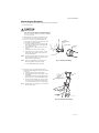
1. Separate wallplate from humidistat.
Fig. 10.
CAUTION
Electrical Hazard
Can cause electrical shock or equipment damage. Disconnect power before beginning installation.
2. Mark the duct-tube hole. Hold the wallplate up to the desired location on the duct and make a mark inside
the duct tube hole.
Fig. 11.
3. Drill the duct-tube hole. Find your mark and drill a 1/2 in. hole in the duct. This is where the duct tube will
be inserted to capture air.
Fig. 12.
M34565A
Setting
Light
Next Auto
System
%
Replace BattReplace Batt
Inside
%
HUMIDITY BOOST
PULL HERE
M34580A
M34581C

HE360 HUMIDIFIER
69-2631ES—13 10
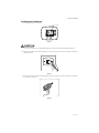
4. Insert the duct tube. Insert the duct tube through the wallplate before securing to the duct.
Fig. 13.
5. Secure the wallplate. Secure the wallplate to the duct with sheet metal screws (provided).
Fig. 14.
6. Run wires through the back plate. Run wires through the top or bottom channel on the back plate when
ductmounted. If installing like a thermostat on a wall, run the wires through the back.
Fig. 15.
M34671B
M34582B
M34610B
RUN WIRES
THROUGH THE
TOP OR BOTTOM
CHANNEL
C
R
U
U
S
S

HE360 HUMIDIFIER
11 69-2631ES—13
WIRING
CAUTION
Hazardous Voltage.
Can cause personal injury or equipment damage.
Disconnect power supply before installing or servicing equipment.
IMPORTANT
— Use THIS wiring diagram—NOT the one supplied with humidistat instructions.
— All wiring must comply with applicable local code, ordinances and regulations.
Wire the humidifier solenoid valve, pressure switch and humidistat. See Fig. 16.
NOTE: It is acceptable to switch the position of the red and white wires when wiring the equipment.
Fig. 16. Wiring the controls.
1. Run two, two-strand thermostat wire bundles from the humidifier to the humidistat. Run one, two-strand
thermostat wire bundle from the humidistat to the pressure switch.
2. Cut lengths of thermostat wire to reach between components, leaving adequate wire at both ends for con-
nections.
3. At the humidifier, connect the two red wires to the red and white wires from wire bundle 1.
4. At the humidifier, connect the two yellow wires to the red and white wires of wire bundle 2.
5. At the humidistat, connect the red and white wires from bundle 1 to R and C (polarity doesn't matter).
6. At the humidistat, connect the red wire from bundle 2 to the upper U terminal.
7. At the humidistat, wire-hut the white wire from bundle 2 to the white wire in bundle 3 (going to the pres-
sure switch).
8. At the humidistat, wire the red wire from bundle 3 to the lower U on the humidistat.
9. At the pressure switch, connect the red and white wires from bundle 3 to the C and NO pressure switch ter-
minals. (NC terminal is not used).
TESTING HUMIDIFIER OPERATION
Checklist
Humidifier is level.
Control wiring was reviewed using circuit diagram.
Humidifier is plugged in.
Feed line has no kinks.
Drain line slopes continuously down and ends at floor drain.
Water hose inside humidifier is connected to PerfectFlow™ water distribution tray.
After installation use the following steps to check the humidifier operation:
1. Turn on the power and the water supply.
2. Turn the H6062 Humidistat all the way up and turn on the heat by setting the thermostat to 10ºF (6ºC)
above room temperature.
IMPORTANT
The furnace blower must be on to activate the humidifier.
3. Make sure that water is flowing out of the drain hose. If water does not flow, see Troubleshooting Your
Humidifier section.
4. Check for leaks.
5. Reset the thermostat and H6062 Humidistat to a comfortable setting for automatic operation.
M39012
AIR
PRESSURE
SWITCH
C
R
U
U
S
S
24 VAC (CONSTANT)
OUTDOOR SENSOR
1
WIRE OUTDOOR SENSOR TO THE S TERMINALS.
1
YELLOW
WIRES
RED
WIRES

HE360 HUMIDIFIER
69-2631ES—13 12
OPERATION
How Your Humidifier Works
Your Resideo humidifier uses the principle that vapor (evaporated water) is created when warm air blows over a
water-soaked area. As the vapor circulates, the relative humidity rises.
Your humidity control monitors the relative humidity and activates the humidifier accordingly. The humidifier
has a water supply that dispenses water evenly over a humidifier pad. The warm dry air, from the furnace, passes
over the humidifier pad and picks up the moist air to circulate it throughout your home.
Humidified air feels warmer and more comfortable so you may be able to lower your thermostat heating
setpoint, which saves money on your heating fuel bills. The end result is that your humidifier gives you a
comfortable environment that is also energy efficient.
Controlling Your Humidity Settings
Your H6062 Humidistat controls your humidifier.
• Choose the humidity control setting using the combination of relative humidity/outdoor temperature setting
scale on your humidity control dial.
• When the outdoor sensor is used, the H6062 will optimize the humidity level while reducing moisture
condensation on the windows. See the H6062 instructions for settings and adjustments.
NOTE: If the outdoor sensor is not used with H6062, as the outside temperature drops, a lower humidity
setting is recommended to accommodate dewpoint effects. These settings should reduce the
accumulation of moisture and ice on windows and other areas of the home.
• Adjust the humidity control setting to adjust for indoor activities such as cooking, showering and clothes
drying, which can cause excessive levels of humidity that can accumulate moisture on your windows.
NOTE: If these activities persist for more than a few hours, set the humidity control to the lowest setting to turn
off the humidifier. If the condition does not improve, ventilate your home to remove the moisture.
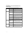
Table 2. Setting your humidistat when outdoor sensor is not used.
MAINTAINING YOUR HUMIDIFIER
A regular maintenance program prolongs the life of your humidifier and makes your home more comfortable.
The frequency of cleaning depends on the condition of your water.
You can use either hard or soft water in your humidifier, but hard water mineral deposits are more difficult to
clean than soft water deposits.
Use the following procedure to clean your Resideo humidifier.
WARNING
Serious Personal Injury Hazard.
Can cause electrical shock and injury from moving parts.
Disconnect power and shut off water supply before removing cover.
IMPORTANT
Never oil any part of the humidifier.
When Outside
Temperature is: Use This Control
Setting:
-20°F (-29°C) 15
-10°F (-23°C) 20
0°F (-18°C) 25
+10°F (-12°C) 30
+20°F (-7°C) 35
Above 20°F (-7°C) 40

HE360 HUMIDIFIER
13 69-2631ES—13
Every 1 to 3 Months (Depending on Water Quality)
1. Disconnect the power and turn off the humidifier water supply.
2. Remove the humidifier cover by unplugging the connector and loosening the thumb screw. Grasp the
cover near the bottom and pull toward you. See Fig. 17.
3. Remove the humidifier pad assembly from the humidifier by grasping the top of the tray and pulling it
toward you.
4. Lift the tray off the pad.
5. Gently pinch the water nozzle catches inward until you can lift the water nozzle off the tray.
6. Carefully remove any mineral deposits from the tray and frame. Be sure the frame drain hole has nothing
blocking it.
Fig. 17. Cleaning your humidifier.
7. Disconnect the drain hose from the drain fitting on the bottom of the humidifier housing.
8. Clean the drain fitting, if necessary.
9. Bend the drain hose to loosen any mineral deposits.
10. Flush the drain hose with pressurized water (a running tap) to clean the hose.
11. Reattach the drain hose to the drain fitting.
12. Snap the water nozzle back on the tray.
13. Be sure the marked end of the pad is facing up. Place the tray on the new pad.
14. Place the humidifier pad assembly in the humidifier housing. Be sure the water feed tube is placed in the
guide slots.
15. Replace the humidifier cover.
16. Verify the humidifier operation by following the steps in the Checking Your Humidifier for Correct Opera-
tion section.
CHECKING YOUR HUMIDIFIER FOR CORRECT OPERATION
After winter startup or servicing, use the following steps to check your humidifier operation:
1. Turn on the humidifier power and water supply.
2. Turn the humidistat to its highest setting and set the thermostat to 10°F (6°C) above the room tempera-
ture.
3. Observe that water is flowing out of the drain hose.
NOTE: The furnace blower must be running to activate the humidifier.
4. Reset the thermostat and humidistat to a comfortable setting for automatic operation.
M12809A
COVER
ASSEMBLY
HUMIDIFIER
PAD ASSEMBLY
FEED TUBE NOZZLE
WATER
DISTRIBUTION TRAY
HUMIDIFIER
HOUSING
THUMB
SCREW

HE360 HUMIDIFIER
69-2631ES—13 14
TROUBLESHOOTING YOUR HUMIDIFIER
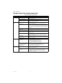
Table 3. Troubleshooting Humidifier.
Problem What to look for What to do
Water leakage Leaking joints. Shut off water.
Tighten connections.
Brass tubing inserts Verify that brass tubing inserts are used.
Saddle valve leaking. If a saddle valve is used as the shut-off valve, verify rubber
pad is installed on saddle valve.
No water to
drain.
Electrical Verify control circuit wiring.
Check all connections.
Humidistat Turn the humidistat up all the way. If "Humidity Boost"
appears on the screen the H6062 is calling for humidity. If it
does not, the installer may not have enabled boost and it is
possible very cold outside temperatures could be restricting
humidity.
Humidifier power Verify that outlet has power.
Solenoid After verifying other wiring components, turn on furnace fan,
turn humidistat up and down, and listen for solenoid to click.
Plumbing Verify plumbing connections.
Check for kinks.
Shut-off valve Verify shut-off valve is turned on. If a saddle valve is used,
verify that needle pierces water line and then backs out
needle to open valve.
Humidifier Remove cover and verify that water flows into distribution
tray.
Drain tubing Verify no obstructions.
Low humidity Furnace blower not
operating.
•Reset circuit breaker or check for blown fuse.
•Check that the furnace power is on.
•Check all external wiring connections.
•Check the humidity control setting.
•Call a professional heating contractor.
Rapid air changes. Drafts
(cold air is dry and is an
added load to the
humidifier).
•Keep doors and windows closed.
•Close fireplace damper when not in use.
•Keep exhaust fan running time to a minimum.
•Seal around doors and windows.
High humidity Condensation on walls. •Turn off humidity control and water until condensation is
completely evaporated.
Heavy condensation on
windows.
•Turn humidity control down low enough to eliminate
condensation caused by moisture from bathing,
mopping, cooking, etc. If moisture persists, more
ventilation is needed.

HE360 HUMIDIFIER
15 69-2631ES—13
LIMITED ONE-YEAR WARRANTY
Resideo warrants this product, excluding battery, to be free from defects in workmanship or materials, under
normal use and service, for a period of one (1) year from the date of first purchase by the original purchaser. If at
any time during the warranty period the product is determined to be defective due to workmanship or materials,
Resideo shall repair or replace it (at Resideo’s option).
If the product is defective,
(i) return it, with a bill of sale or other dated proof of purchase, to the place from which you purchased it; or
(ii) call Resideo Customer Care at 1-800-468-1502. Customer Care will make the determination whether the
product should be returned to the following address: Resideo Return Goods, 1985 Douglas Dr. N., Golden Valley,
MN 55422, or whether a replacement product can be sent to you.
This warranty does not cover removal or reinstallation costs. This warranty shall not apply if it is shown by
Resideo that the defect was caused by damage which occurred while the product was in the possession of a
consumer.
Resideo’s sole responsibility shall be to repair or replace the product within the terms stated above. RESIDEO
SHALL NOT BE LIABLE FOR ANY LOSS OR DAMAGE OF ANY KIND, INCLUDING ANY INCIDENTAL OR
CONSEQUENTIAL DAMAGES RESULTING, DIRECTLY OR INDIRECTLY, FROM ANY BREACH OF ANY
WARRANTY, EXPRESS OR IMPLIED, OR ANY OTHER FAILURE OF THIS PRODUCT.
Some states do not allow the exclusion or limitation of incidental or consequential damages, so this limitation
may not apply to you.
THIS WARRANTY IS THE ONLY EXPRESS WARRANTY RESIDEO MAKES ON THIS PRODUCT. THE DURATION OF
ANY IMPLIED WARRANTIES, INCLUDING THE WARRANTIES OF MERCHANTABILITY AND FITNESS FOR A
PARTICULAR PURPOSE, IS HEREBY LIMITED TO THE one YEAR DURATION OF THIS WARRANTY. Some states
do not allow limitations on how long an implied warranty lasts, so the above limitation may not apply to you.
This warranty gives you specific legal rights, and you may have other rights which vary from state to state. If you
have any questions concerning this warranty, please write Resideo Customer Care, 1985 Douglas Dr, Golden
Valley, MN 55422 or call 1-800-468-1502.

HE360 HUMIDIFIER
© 2022 Resideo Technologies, Inc. All rights reserved. The Honeywell Home trademark is used under license from Honeywell International, Inc.
This product is manufactured by Resideo Technologies, Inc. and its affiliates.
Todos los derechos reservados. La marca comercial Honeywell Home se utiliza bajo licencia de Honeywell International, Inc.
Este producto es fabricado por Resideo Technologies, Inc. y sus afiliados.
www.resideo.com
Resideo Technologies, Inc.
1985 Douglas Drive North, Golden Valley, MN 55422
1-800-468-1502
69-2631ES—13 M.S. Rev. 09-22 | Printed in United States

MANUAL DE INSTRUCCIONES
69-2631ES-13
Humidificador HE360
HE360A1075
HE360D1075
Leer antes de instalar
Entrada: 120 V CA, 60 Hz, 0.7A

HUMIDIFICADOR HE360
69-2631ES—13 2
BIENVENIDO
Le damos la bienvenida al mundo confortable del aire humidificado. Cuando utilice su humidificador Resideo,
observará que su piel no estará tan seca, y que la garganta rasposa y los conductos nasales irritados que
agravan las alergias y el asma mejorarán continuamente.
También ha dado el primer paso para disminuir la electricidad estática que crea cuando camina en la alfombra
y, luego, toca el televisor, la computadora, el pomo de metal de la puerta o su mascota. Sus muebles y la madera
también se benefician de la diferencia que el aire humidificado crea.
¡Felicitaciones! Ha hecho una estupenda inversión para mejorar el confort de su hogar.
INSTALACIÓN
Preparación para la instalación
Asegúrese de tener las herramientas y los accesorios necesarios del Cuadro 1 y de la lista Herramientas y
accesorios sugeridos antes de comenzar la instalación.
Herramientas y accesorios sugeridos
Entre las herramientas y los accesorios necesarios para la instalación, se incluyen los siguientes:
• Tijera de hojalata.
•Destornillador.
• Llave ajustable o de boca abierta.
• Taladro, punzón o lezna.
•Nivel.
• Cable de dos conductores, de calibre 18, para termostato.
• Tubo de agua de alimentación de 1/4 in (6,35 mm) de diámetro exterior.
• Tubo de drenaje de 1/2 in (12,7 mm) de diámetro interior.
• Accesorios y válvula de cierre de agua de 1/4 in (6,35 mm) que cumplan con el código.
Accesorios incluidos
Table 1. Accesorios incluidos.
Cantidad Accesorio
1 bolsa Elementos de montaje y conexión:
Empalmes para cables (4)
Tornillos Nº 8 para l lámina de metal (18)
Abrazadera para eltubo de drenaje
Abrazaderas de montaje para el tubo de alimentación (6)
Insertos de latón (2)
Aros de compresión plásticos (2)
1 Interruptor de presión
1 Humidistato H6062

HUMIDIFICADOR HE360
3 69-2631ES—13
Cómo determinar la mejor ubicación para el humidificador
PRECAUCIÓN
Temperatura y peligro de presión estática.
Puede dañar la propiedad o el equipo.
Ubique el humidificador donde la temperatura ambiente esté entre 0 °C (32 °F) y 71 °C (160 °F).
No instale el humidificador donde pudiesen ocurrir temperaturas de congelamiento.
Cerciórese de que la presión estática en el plenum no sea mayor de 0.4 en la columna de agua y que la
presión de agua no sea mayor de 124 psi.
• Elija un lugar para el humidificador en el plenum de alimentación (corriente de aire cálido). Consulte la Fig. 1.
• Elija un lugar que no pueda dañar el serpentín A del aire acondicionado durante la instalación.
• No ubique el humidificador en el interior del sistema de calefacción.
• Permita el espacio libre adecuado al frente y sobre el humidificador para que pueda retirar fácilmente la
cubierta para efectuar el mantenimiento de rutina.
— Monte el humidificador, al menos, 78 mm (3 in) por encima del sistema de calefacción para permitir
suficiente espacio para la válvula del solenoide y la tubería de drenaje.
— Monte el humidificador en un espacio acondicionado para evitar el congelamiento.
Fig. 1. Ubicaciones de instalación típicas para el humidificador.
Selección de la ubicación del suministro de agua
• Use agua dura o blanda en el humidificador y agua caliente o fría. El caudal de agua, con el humidificador en
funcionamiento, es de 3,5 gal/h (13 l/h) para enjuagar la almohadilla y proporcionar humedad para la
evaporación.
• Asegúrese de que la longitud del tubo de agua de alimentación de 1/4 in sea adecuada para conectar la
válvula de cierre del suministro de agua con la válvula de solenoide del humidificador.
Ubicación del drenaje de piso más cercano
• Elija la ubicación con acceso a un drenaje de piso para proporcionar la salida de la condensación del aire
acondicionado y el drenaje del humidificador.
• Si no existe un drenaje disponible, recomendamos que instale el tambor Resideo para toda la casa o el
humidificador de disco. Cerciórese de que los tubería de drenaje sean adecuados para la conexión desde el
drenaje del humidificador hasta el drenaje de piso.
MS12808
HORIZONTAL
PLATAFORMA BAJA
RETORNO
RETORNO
RETORNO
RETORNO
FLUJO
DESCENDENTE
PLATAFORMA
ALTA

HUMIDIFICADOR HE360
69-2631ES—13 4
Elección de la ubicación del humidistato
• Elija una ubicación para el humidistato en el plenum de retorno o en la pared del espacio habitable.
— El montaje en el plenum de retorno es la instalación más fácil para el circuito de cableado de los
controles.
Para el montaje en el conducto de retorno, el humidistato debe montarse por encima del humidificador o
desviador, de modo que detecte adecuadamente la humedad relativa del espacio habitable. Ubique el control, al
menos, 203 mm (8 in) por encima del humidificador en el conducto de aire de retorno. (Consulte la Fig. 2).
Fig. 2. Elección de la ubicación del conducto para el humidistato.
Ubicación más cercana a un tomacorriente de 120 V
• Elija la ubicación con acceso a un tomacorriente. Si no está disponible, contacte a un electricista para que
instale un tomacorriente.
• Cerciórese de que el cable del humidificador llegue desde el humidificador hasta el tomacorriente.
• Cerciórese de que el cable de termostato sea adecuado para llegar desde el solenoide del humidificador
hasta el interruptor de presión y el humidistato.
Instalación del humidificador
ADVERTENCIA
Voltaje peligroso
Puede causar lesiones personales o daño al equipo.
No corte ni taladre en ningún accesorio de aire acondicionado o de electricidad.
PRECAUCIÓN
Riesgo de bordes afilados en la instalación.
Puede ocasionar lesiones personales.
Use guantes y gafas de seguridad.
1. Desconecte el suministro eléctrico del sistema de manejo de aire en el interruptor de circuito.
2. Trace una línea nivelada en el plenum en la ubicación elegida para el humidificador. (La nivelación
garantiza el desempeño óptimo del humidificador).
3. Ubique la plantilla (formulario número 69-2641 que se incluye en la caja).
4. Encinte la plantilla en su posición y trace alrededor de la plantilla.
5. Retire la plantilla y corte cuidadosamente la abertura rectangular.
6. Desensamble el humidificador; retire la cubierta y saque el ensamble de la almohadilla del humidificador.
Consulte la Fig. 3.
UBICACIÓN
ALTERNA
AIRE DE
RETORNO AIRE DE
RETORNO
6 pulgadas (152 mm)
MÍNIMO
15 pulgadas (381 mm)
MÍNIMO
UBICACIÓN
PREFERENTE
CONDUCTO DE
AIRE DE RETORNO
MS34579B
Page is loading ...
Page is loading ...
Page is loading ...
Page is loading ...
Page is loading ...
Page is loading ...
Page is loading ...
Page is loading ...
Page is loading ...
Page is loading ...
Page is loading ...
Page is loading ...
-
 1
1
-
 2
2
-
 3
3
-
 4
4
-
 5
5
-
 6
6
-
 7
7
-
 8
8
-
 9
9
-
 10
10
-
 11
11
-
 12
12
-
 13
13
-
 14
14
-
 15
15
-
 16
16
-
 17
17
-
 18
18
-
 19
19
-
 20
20
-
 21
21
-
 22
22
-
 23
23
-
 24
24
-
 25
25
-
 26
26
-
 27
27
-
 28
28
-
 29
29
-
 30
30
-
 31
31
-
 32
32


Honeywell Home HE360 Owner's manual
- Category
- Dehumidifiers
- Type
- Owner's manual
- This manual is also suitable for
Ask a question and I''ll find the answer in the document
Finding information in a document is now easier with AI
in other languages
Related papers
-
 Honeywell Home HE360 User manual
-
Honeywell Home HE365 User manual
-
 Honeywell Home HE280D2001/U User guide
-
Honeywell Home HE400A2022/U Owner's manual
-
Honeywell HE360A Owner's manual
-
 Honeywell Home FC313R1424/U User guide
-
 Honeywell Home CG511A1000/U Installation guide
-
Honeywell HE240A Installation guide
-
Honeywell HE160A User manual
-


Other documents
-
-
-
Honeywell HE105 Whole Home Bypass Humidifier Installation guide
-
Honeywell HE360 User manual
-
Honeywell HE365B Installation guide
-
-
Honeywell HE220 User manual
-
Honeywell HE205 Humidifier User guide
-
-
resideo HE150 Installation guide