Page is loading ...

INGERSOLL-RAND
CENTAC
CENTACCENTAC
CENTAC
Instruction Manual


Copyright Notice
2000 Ingersoll-Rand Company
Proprietary Notices and Disclaimer
PROPIETRAY NOTICES
Copyright 1999 INGERSOLL-RAND COMPANY
CENTAC is federally registered trademark of INGERSOLL-RAND COMPANY.
CONFIDENTIAL AND TRADE SECRET INFORMATION.
This manual contains confidential
and trade secret information owned by Ingersoll-Rand Company (hereinafter referred to as
“Proprietary Matter”). In consideration of the disclosure of the Proprietary Matter herein to
the authorized recipient hereof, the recipient shall treat the Proprietary Matter as secret and
confidential; shall not disclose or give such Proprietary Matter to third parties without the
express written authorization of INGERSOLL-RAND; shall not use the Proprietary Matter
except to the extent necessary to use or service the equipment disclosed herein; and shall
disclose such Proprietary Matter only to those of its employees whose use or knowledge of
the Proprietary Matter is necessary. This manual shall be returned upon request by
Ingersoll-Rand Company. The unauthorized use of this manual may be punishable by law.
DISCLAIMERS
PROVIDED “AS IS”. THIS MANUAL AND THE CONTENTS THEREOF ARE PROVIDED
“AS IS” AND WITHOUT ANY IMPLIED WARRANTIES.


INSTRUCTION MANUAL
Centac Instruction Manual
2000 Ingersoll-Rand Company
Date of Issue: December, 2003
Ingersoll-Rand
Warranty and Limitation of Liability
Warranty
The Seller warrants that the Equipment manufactured by it and delivered hereunder will be free of defects in material
and workmanship for a period of twelve months from the date of placing the Equipment in operation or eighteen months
from the date of shipment, whichever shall first occur*. The Buyer shall be obligated to promptly report any failure to
conform to this warranty, in writing to the Seller within said period, whereupon the Seller shall, at its option, correct such
nonconformity, by suitable repair to such Equipment or, furnish a replacement part F.O.B. Jobsite, provided the Buyer
has stored, installed, maintained and operated such Equipment in accordance with good industry practices and has
complied with specific recommendations of the Seller. Accessories or equipment furnished by the Seller, but
manufactured by others, shall carry whatever warranty the manufacturers have conveyed to the Seller and which can
be passed on to the Buyer. The Seller shall not be liable for any repairs, replacements, or adjustments to the
Equipment or any costs of labor performed by the Buyer or others without the Seller's prior written approval.
The effects of corrosion, erosion and normal wear and tear are specifically excluded. Performance warranties are
limited to those specifically stated within the Seller's proposal. Unless responsibility for meeting such performance
warranties are limited to specified tests, the Seller's obligation shall be to correct in the manner and for the period of
time provided above.
THE SELLER MAKES NO OTHER WARRANTY OR REPRESENTATION OF ANY KIND WHATSOEVER,
EXPRESSED OR IMPLIED, EXCEPT THAT OF TITLE, AND ALL IMPLIED WARRANTIES OF MERCHANTABILITY
AND FITNESS FOR A PARTICULAR PURPOSE, ARE HEREBY DISCLAIMED.
Correction by the Seller of nonconformities whether patent or latent, in the manner and for the period of time provided
above, shall constitute fulfillment of all liabilities of the Seller for such nonconformities, whether based on contract,
warranty, negligence, indemnity, strict liability or otherwise with respect to or arising out of such Equipment.
The Buyer shall not operate Equipment which is considered to be defective, without first notifying the Seller in writing of
its intention to do so. Any such use of Equipment will be at the Buyer's sole risk and liability.
* It is understood that when Techtrol Gold III Lubricant is purchased, the warranty period for the compressor airend
bearings, seals, rotors, and bullgear only, less motor, cooler, and accessories, shall be considered revised to read
“twenty-four months from the date of start up, or thirty months from the date of shipment, whichever first occurs”.
*In addition, this warranty period (unoperational shelf life or operational life) may also vary from the standard (12
months from startup or 18 months from shipment), if the Buyer has purchased the extended warranty options outlined
within Seller’s proposal.
Limitation of Liability
The remedies of the buyer set forth herein are exclusive, and the total liability of the seller with respect to this contract,
whether based on contract, warranty, negligence, indemnity, strict liability or otherwise, shall not exceed the purchase
price of the unit of equipment upon which such liability is based.
The seller and its suppliers shall in no event be liable to the buyer, any successors in interest or any beneficiary or
assignee of this contract for any consequential, incidental, indirect, special or punitive damages arising out of this
contract or any breach thereof, or any defect in, or failure of, or malfunction of the equipment hereunder, whether based
upon loss of use, lost profits or revenue, interest, lost goodwill, work stoppage, impairment of other goods, loss by
reason of shutdown or non-operation, increased expenses of operation, cost of purchase of replacement power or
claims of buyer or customers of buyer for service interruption whether or not such loss or damage is based on contract,
warranty, negligence, indemnity, strict liability or otherwise.
8/14/00 DOM/INT’L


INSTRUCTION MANUAL
Centac Instruction Manual
2000 Ingersoll-Rand Company
Date of Issue: December, 2003
NOTICE
On receiving the Centac compressor, be sure to inspect
the unit for evidence of damage during shipment.
Immediately notify the carrier and the nearest
Ingersoll-Rand representative if any damage is noted.
The compressor should be stored on a level floor or
supports, in a dry protected area. Based on these
conditions, the Centac compressor has been prepared for
180 days of storage. If the unit is to be stored for periods
longer then 180 days, it will require additional protection.
WARNING
Not to be used for breathing air application. Ingersoll-Rand
company air compressors are not designed, intended or approved
for breathing air applications. Ingersoll-Rand does not approve
specialized equipment for breathing air applications and assumes
no responsibility or liability for compressors used for breathing air
service.

CENTAC INSTRUCTION MANUAL
Centac Instruction Manual
2000 Ingersoll-Rand Company
Date of Issue: 12 September, 2000
Table of Contents
Section 1 Planning & Installation
Section 2 Description
Section 3 Operation
Section 4 Maintenance
Section 5 Troubleshooting
Section 6 Parts & Service

SECTION 1 PLANNING & INSTALLATION
Centac Instruction Manual
2000 Ingersoll-Rand Company
Date of Issue: December, 2003
Section 1 – Planning & Installation
NOTE
Where found in this manual, the word must means that the specification must be met
to validate the warranty.
The word should means that it is a desirable condition, but not mandatory for the
operation of the compressor and failure to meet this specification does not
necessarily affect the warranty. Deviation from these recommendations may severely
limit efficient operation or interfere with the service technician’s ability to perform
maintenance on the machine.
Safety
This manual contains instructions for planning of the installation, operation and maintenance
of your Ingersoll-Rand centrifugal air compressor that has been designed to provide safe
and reliable service. However, it is both a pressure system and a rotating machine,
therefore, the operator(s) must exercise good judgment and proper safety practices to
prevent personal injury and avoid damage to the equipment and surroundings. The
instructions in this manual are intended for personnel with a general training in operation and
maintenance of centrifugal air compressors.
Safety Program
It is assumed that your safety department has established a safety program based on a
thorough analysis of industrial hazards. Before installing, operating or performing
maintenance on the compressor and associated components described in this manual,
review the safety program to ensure that it covers the hazards that come with high speed
rotating machinery.
It is also important to consider the hazards associated with electrical power, hot oil, high
pressure and temperature liquids, toxic liquids and gases, and flammable liquids and
gases. Proper installation and care of protective guards, shutdown devices, and over
pressure protection equipment are also essential parts of any safety program.
Special precautionary measures include:
• Eliminate the possibility of power going to the equipment at any time when
maintenance work is in progress.
• Prevent rotation due to reverse flow.
• Ensure that the block valve is closed and tagged during maintenance.
In general, all personnel should be guided by the basic rules of safety associated with the
equipment and the process.

SECTION 1 – PLANNING & INSTALLATION
Centac Instruction Manual
2000 Ingersoll-Rand Company
Date of Issue: 12 September, 2000
Safety Procedures
Throughout this manual, you will encounter boxes with the words WARNING, CAUTION,
and NOTE. These are intended to emphasize certain areas where precaution is needed.
This is in the interest of personal safety and satisfactory compressor operation and
maintenance. The definitions of these words are as follows:
WARNING
An operating procedure, practice, etc. that, if not correctly followed, could
result in severe personal injury, or loss of life.
CAUTION
An operating procedure, practice, etc. that, if not strictly observed, could result
in damage to, or destruction of equipment.
NOTE
An operating procedure, condition, etc. that is essential to highlight.
The information in this manual does not relieve operating and maintenance personnel of
the responsibility of exercising normal good judgment in operation and care of the
compressor and its components. We suggest that all personnel follow the safety
precautions associated with this type of equipment.
In addition to the many obvious safety rules, follow the safety procedures listed below when
personnel are operating or maintaining Centac compressors:
1. DO NOT USE THE DISCHARGE AIR FOR BREATHING. IT COULD CAUSE
SEVERE INJURY OR DEATH. Consult a filtration specialist for additional filtration
and treatment equipment to meet health and safety standards.
2. Pull the main disconnect switch and disconnect any separate power lines before
attempting to work or perform maintenance on the unit.
3. Do not attempt to remove any compressor parts without first relieving the entire
system of pressure.
4. Do not attempt to service any part while the machine is operating.
5. Do not operate the compressor at pressures in excess of its rating as indicated on
the compressor nameplate.
6. Do not operate the compressor at speeds in excess of its rating (or less than its
rating) as indicated on the driver nameplate.

SECTION 1 PLANNING & INSTALLATION
Centac Instruction Manual
2000 Ingersoll-Rand Company
Date of Issue: December, 2003
7. Do not remove any guards, shields, or screens while the compressor is operating.
8. Periodically check all safety devices for proper operation.
9. Be cautious when using compressed air. Pressurized air can cause serious injury to
personnel.
10. Be sure no tools, rags, or loose parts are left on the compressor or drive parts.
11. Do not use flammable solvents for cleaning parts.
12. Exercise cleanliness during maintenance and when making repairs. Keep dirt away
from parts by covering parts and exposed openings with clean cloth or kraft paper.
13. Do not operate the compressor without guards, shields, and screens in place.
14. Do not operate compressor in areas where there is a possibility of ingesting
flammable or toxic fumes.
15. Shut down the compressor before removing any caps or plugs. Oil or air under
pressure can cause severe personal injury, or death.
NOTE
The owner, lease holder, or operator of the compressor is hereby notified and
forewarned that any failure to observe common safety precautions, whether stated
herein, or not, may result in damage or injury.
Ingersoll-Rand Company expressly disclaims responsibility or liability for any injury or
damage caused by failure to observe those specified, or other common precautions
or by failure to exercise that ordinary caution, common sense, and due care required
in operating or handling the compressor even though not expressly specified above.
Receiving/Handling/Storage
Receiving
Centac compressors are shipped in first class condition. They have been inspected prior to
leaving the factory. Loading of the compressor has been supervised by Ingersoll-Rand
personnel to ensure that the unit has not been damaged during loading and that all
accessory equipment has been properly documented.
Inspect the compressor for shipping damage before removing the compressor from
carrier’s vehicle. If damage or indication of rough handling is evident, file a claim with the
carrier at once, and notify your Ingersoll-Rand representative.
Remove only the shipping notice. Do not remove tags pertaining to lubrication, operation,
and storage. Read all tags and instructions.
Document receipt of all items included with the compressor, but packed separately. Make a
list of any items that were not received and notify your Ingersoll-Rand representative. Store
all items either with the compressor or in an appropriate secured area.

SECTION 1 – PLANNING & INSTALLATION
Centac Instruction Manual
2000 Ingersoll-Rand Company
Date of Issue: 12 September, 2000
Handling/Lifting
An experienced rigger should move and
install the compressor. Adequate rigging and
lifting equipment must be provided to safely
handle the unit. Use spreader bars to
prevent damage to piping, tubing, gauges,
and other accessory equipment. Provisions
for lifting the unit are located at the corners
of the baseplate (see Figure 1.1).
Installation of a Centac compressor can best
be done by the use of an overhead crane.
Lifting points have been provided in the
baseplate for the purpose of lifting the
complete unit. To facilitate lifting and avoid
possible damage, spreader bars are
recommended. Figure 1 illustrates the lift
points for a standard unit. An overhead rail
with a chain hoist will also simplify the
removal of the largest component parts when
maintenance is required.
Figure 1.1 Lifting Diagram for Standard Unit
WARNING
Do not lift the unit by the lifting eyes on the compressor or driver. These eyes
are for lifting the individual component parts only. Damage to equipment and injury to
personnel could result from misuse of the lifting eyes.
Storage
The compressor, as it is shipped from the factory (flanges banked and desiccant bags
placed at inlet and discharge), can be stored on a level surface in a controlled environment
for up to 180 days after the ship date tagged on the compressor unit without requiring long-
term storage preparation. The unit must be started within the first 180 days following
shipment from Ingersoll-Rand to assure the full 12-month operational warranty after start-
up. Store all loose/spare parts in a controlled environment for adequate protection prior to
usage.
At the termination of the storage period, the motor should be given continuity and insulation
tests before connecting to a power line. Specific motor start-up instructions provided by the
motor supplier must be followed.
If the unit is to be stored for periods longer than 180 days, or in an uncontrolled
environment, the unit will require additional protection. Consult your local Ingersoll-Rand
representative for long term storage requirements and extended warranty coverage.
Consider a unit in storage when:

SECTION 1 PLANNING & INSTALLATION
Centac Instruction Manual
2000 Ingersoll-Rand Company
Date of Issue: December, 2003
• It has been delivered to the job site and is awaiting installation.
• It has been installed but operation is delayed pending completion of plant
construction.
• There are long periods (30 days or more) between operating cycles.
• The plant (or department) is shut down.
Installation Planning
General
Proper installation is a critical component of satisfactory operation of all rotating machinery.
Proper support of the machinery is required to give maximum reliability at minimum
operating cost. In addition, a well-designed installation will result in lower installation and
operating costs. See the General Arrangement drawing for compressor/customer connection
details and lift points. Contact your local Ingersoll-Rand representative for further
information.

SECTION 1 – PLANNING & INSTALLATION
Centac Instruction Manual
2000 Ingersoll-Rand Company
Date of Issue: 12 September, 2000
Plant Layout
The location of a packaged centrifugal compressor within a plant facility is very important.
The compressor should be located in an area that is accessible to operators and
maintenance personnel.
Machinery should be installed where it is easily accessible for observation and maintenance.
Operation and maintenance personnel will generally give better attention to a compressor
located in a well planned, accessible area. Compressors installed in elevated locations or in
pits should have stairways, catwalks, etc. for easy access to the machinery.
During installation, machinery can best be handled with overhead crane facilities. Adequate
space should be provided to permit easy handling of the unit during installation (see the
General Arrangement drawing for compressor maintenance space). Provide floor space in
the vicinity of machinery where parts may be placed during periodic inspection of the rotating
elements and internal parts. Make provisions for clearance requirements specified on the
General Arrangement drawing.
Indoor/Outdoor Installation
The unit may be installed indoors or outdoors. For an outdoor installation, protective
measures are necessary for the motor, control panel, and other items. It is important when
the compressor package is purchased that Ingersoll-Rand is made aware of plans and
makes any necessary recommendations for outdoor installation.
If the unit is an indoor installation, a heated building is preferred. Provide adequate space for
ease of handling during installation.
Ventilation
Ventilation around the unit is important. The unit should not be installed in a damp or dusty
atmosphere or where corrosive vapors may enter the compressor or driver.
On motor driven units the heat radiated to air in the room will be approximately 6% of the
total horsepower: 1HP=42.4 BTU/MIN
1KW=56.9 BTU/MIN
Noise
In areas where noise could be a problem, it is important to treat hard reflective surfaces in
the area. Avoid installing the unit in an area with low hard ceilings and walls.
Foundation
The compressor foundation does not need to be massive but should be sufficient to provide
support for the unit.
Since there are no out-of-balance forces, such as, reciprocating or shock loads; all loads on
the foundation may be considered as static loads. If the unit is to be located in an area with
other machinery, it is essential that vibrations are not transmitted to the compressor.
Isolation pads are recommended in these instances.
For the Centac compressor package, a simple continuous concrete pad or steel support
structure is recommended for each compressor. Precautions should be taken to ensure a
reasonably uniform base around the pad. Uneven settling or thermal expansion could cause
machinery misalignment. Appropriate bolting must be used to keep the compressor in place.
Refer to the General Arrangement drawing for location and size of anchor boltholes.

SECTION 1 PLANNING & INSTALLATION
Centac Instruction Manual
2000 Ingersoll-Rand Company
Date of Issue: December, 2003
NOTE
The design of the foundation is the responsibility of the customer. These comments
are offered as an aid to assure a successful installation, but Ingersoll-Rand Company
cannot assume the responsibility for the design. We recommend that the customer
consult a specialist skilled in the design of machinery foundations.
Leveling
The Centac compressor should be leveled at the time of installation. To level the unit, place
it over the anchor bolts with the feet resting on steel wedges or shims, if necessary (see
Figure 1.3).
The unit may be leveled using a machinist level or transit level. When a machinist level is
used, start at one end of the unit and work side to side toward the opposite end, placing the
level on the machined baseplate compressor pads. The compressor should be level from
0 to 0.1 inch/foot (0 to 8 mm/M).
After the unit is level with snug (not tightened) anchor bolts, the coupling should be aligned.
Some baseplate distortion may be noted but this is unimportant so long as the machine pads
remain level. Precise driver alignment is not required until the time of start-up, but should be
within 1/16 inch (1.5 mm). Follow the procedures found in the Operation Manual once the
compressor arrives on site. The General Arrangement drawing lists the values for the
coupling alignment. Record the values obtained, but do not dowel the driver or install the
coupling spacer.
Baseplate
Anchor bolt
Leveling wedges
Foundation/pad
Leveling shims
Figure 1.3.
Wedge and shim placement
After the coupling has been brought into rough alignment and the alignment values have
been recorded, the Centac compressor is ready for grouting.

SECTION 1 – PLANNING & INSTALLATION
Centac Instruction Manual
2000 Ingersoll-Rand Company
Date of Issue: 12 September, 2000
Grouting
Grouting is the most common method for permanent installation of rotating machinery. Fill
the area between baseplate and foundation with a minimum of 1” of grout to create a
uniform bearing surface. Common grouting materials are non-shrinking concrete and epoxy
type grouts.
Grout is installed in the space below the baseplate beams after preparation of the foundation
surface by chipping. After the grout has set, any wedges or shims used to level the unit must
be removed and the remaining spaces filled with grout.
Air Piping
A well-designed air piping configuration requires proper planning and execution. This
section covers the following topics:
• Inlet air piping and filters
• Bypass air piping
• Expansion joints
• Discharge air piping
• Discharge air piping for multi-compressor installation
• Receivers
• Control air piping / filtration
• Instrument air piping
Centac products have no design provision for accepting the full weight of external piping
connections. The discharge, inlet, bypass, water, and other piping connected to the
machine must be self-supporting. Adequate piping supports are necessary to prevent
excessive dead loads on the flanges of rotating machinery.
Piping alignment to the compressor mating flanges is essential. The piping must be
installed and supported to avoid strains on the casing. Misalignment, which is a frequent
cause of vibration, can often be traced directly to piping strains. Three sources of piping
strains are:
• Dead weight of the piping itself
• Expansion or contraction of the piping as it undergoes temperature change
• Pressure within the piping
In the practical sense, if any pipe needs to be levered or pried into position to match up the
flange face with the compressor, there will be excessive pipe strain. A properly matched up
pipe flange will have just enough space to slip in a gasket, will allow all flange fasteners
(bolts, studs, etc.) to pass through the flange bolt bores without adjustment of the mating
flanges, and does not twist in any plane when the fasteners are tightened.
All piping connected to the Centac compressor should have provisions for compressor
maintenance. This usually means that there are flanged sections or unions in the
connecting pipe. A sufficient number of removable sections of pipe should be provided to
allow ease of maintenance and repair. Failure to make provisions for repair will result in
difficulty during disassembly.

SECTION 1 PLANNING & INSTALLATION
Centac Instruction Manual
2000 Ingersoll-Rand Company
Date of Issue: December, 2003
Summarizing, a satisfactory piping arrangement can normally be obtained by giving proper
attention to:
1. Providing adequate support for all parts of the piping system.
2. Allowing for expansion in a manner that will avoid piping strains on the compressor.
3. Installing a sufficient number of anchors in the piping system so that direction and
magnitude of expansion are controlled.
4. Designing the inlet and discharge piping so as to provide smooth flow with minimum
pressure drop and uniform velocity over the entire area of piping.
NOTE
The design of the piping system is the responsibility of the customer. Data and
comments are offered as an aid to ensure a successful installation, but
Ingersoll-Rand cannot assume responsibility for its design or installation. We
recommend that the customer consult a specialist skilled in the design of piping
systems to supplement and interpret the piping information and to ensure a
successful installation.
The inlet pipe and filter must be inspected before startup by an Ingersoll-Rand
factory certified service representative.
NOTE
All air and water piping to and from the inlet and discharge port connections must
take into account vibration, pulsations, temperature, maximum pressure applied,
corrosion, and chemical resistance. Where compatibility questions may exist,
contact your Ingersoll-Rand representative.
Inlet Air Piping
Inlet air is the lifeline of any compressor. It is imperative that the compressor receives clean
filtered air to function correctly with low maintenance. A well thought out piping design will
save many hours and dollars in maintenance.
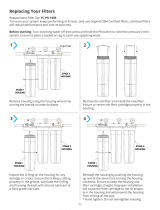
Whether the inlet air piping is supplied with the compressor or by others it must be inspected
for cleanliness by an Ingersoll-Rand factory certified service technician prior to start-up.
Maintenance
It is advisable that you install spool pieces that allow the casing sections to be removed and
the piping to be out of the way of personnel for maintenance. The inlet pipe will be removed
for inspection at start-up.
The importance of always operating the compressor with clean air inlet piping must be
stressed. No compressor will accept the injection of foreign material into the operating
components without possible damage or loss of performance.

SECTION 1 – PLANNING & INSTALLATION
Centac Instruction Manual
2000 Ingersoll-Rand Company
Date of Issue: 12 September, 2000
Inlet Air Filter
An inlet air filter should be mounted by the customer at a suitable location. At minimum, it
should be a high efficiency two-stage unit designed to remove 99.97% of all particles larger
than 2 microns and 90% of all particles larger than 0.4 microns. For adverse environmental
conditions, a more efficient inlet air filter is recommended.
The inlet filter is normally oversized to increase the time between element changes and
reduce the velocity through the filter to give a lower noise level.
Routine inspection of the filter is recommended and the addition of instrumentation to
indicate pressure drop across the filter elements is also suggested. When this drop
increases substantially, the elements should be cleaned or replaced.
Remote Inlet Air Filter (Panel Type)
When the filter is mounted at a remote location with the inlet air piping supplied by others,
the following recommendations should be observed.
The remote inlet air filter should be, at minimum, a high efficiency unit designed to remove
99.97% of all particles at 2 microns or larger. For adverse environmental conditions it is
recommended that you use a special filter, such as:
• A 0.3 micron inlet air filter
• An inertial spin filter
• A chemical type filter
Check with your Ingersoll-Rand representative for specific filter information.
The air filter should be located as close to the unit as possible to minimize pressure drop. If
the filter is located outside the compressor building, the inlet housing should be at least
8 to 10 feet above the ground or roof and 6 feet away from the side of a wall.
(See Figure 1.4)
Access to the filter should be provided with ample room around the filter for maintenance. A
permanent platform should always be built around elevated filters to provide safety for
personnel assigned to changing filter elements.
For best performance the inlet air piping should conform to the following recommendations:
• The inlet piping, from the inlet filter to the compressor, must be clean and made from a
non-rusting material such as stainless steel, aluminum, or PVC, and suitably flanged so
that it may be inspected in sections.
• Inlet piping should be short and direct, with the combined filter and piping pressure drop
less than 0.3 psi (2.1 kPa[a]).
• Always use long radius elbows.
• Transitions in pipe diameters should be gradual.
• Any horizontal run of pipe should be installed so that condensation in the piping will run
away from the compressor.
• Drain valves should be installed in the inlet piping at low points to allow the removal of
condensation.

SECTION 1 PLANNING & INSTALLATION
Centac Instruction Manual
2000 Ingersoll-Rand Company
Date of Issue: December, 2003
Figure 1.4
Inlet Air Piping – Air Filter
Bypass Air Piping
Atmospheric bypass piping vents the compressed air when the compressor is running
unloaded or at partial load. Bypass piping should be well supported to minimize loading on
the compressor flange. Care should be taken in the piping design so that all alignments can
be made in the piping.
A bypass silencer should be installed in the atmospheric bypass line to reduce noise. A
suitable silencer is offered as an option with the compressor package and is customer
mounted. The silencer has acoustic absorption material at a controlled density. The silencer
is usually installed close to the compressor and the vent piped outside. Alternately, the
silencer may be installed outside the building. Consult the certified drawings for complete
details of the silencer.
For sound attenuation in piping, a straight horizontal run of pipe from the compressor flange,
at least 8 pipe diameters long, is suggested before entering a long radius elbow (see Figure
1.5). The silencer should be kept as close to the compressor as possible and the total length
of pipe kept short. In noise critical areas, the discharge piping from the silencer may be
lagged to further reduce sound.
Inlet filter
Roof line
Work platform
p
p
0.3 psi (2.1 kPa[a])
Max
8 ft. (2.4 M) min.
Pipe hangars
Removable
transition piece
Entire pipe to be
non-corroding material
Inlet air temp
Long radius elbow
Low point drain
Inlet valve
Minimum of 4
pipe diameters

SECTION 1 – PLANNING & INSTALLATION
Centac Instruction Manual
2000 Ingersoll-Rand Company
Date of Issue: 12 September, 2000
Figure 1.5
Model Bypass Pipe
Discharge piping from the silencer should be sized so that the maximum backpressure on
the silencer is 5 psi or 35 kPa (a). Standard silencers are equipped with ANSI 150# standard
flanges. Bypass piping to the silencer should be of the same diameter or larger than the
bypass valve. Piping from the bypass silencer should be of the same size or larger than the
silencer discharge. Refer to the certified drawing for complete details of silencer.
The bypass piping should be suitably flanged so that a minimum amount of pipe needs to be
removed during major maintenance. This will reduce maintenance time.
The end of the pipe should be turned down or have a short run of pipe to prevent rain and
snow from entering the bypass piping. Expanded metal should be installed on the end of the
pipe to prevent large objects and animals from entering the pipe when the compressor is
stopped. To remove condensation from the piping, install a drain in the lowest part.
Expansion Joints
With proper piping layout and installation, expansion joints may not be required on all
compressors. However, expansion joints are required on:
• All hot air discharge compressors (no internal aftercooler)
• All steam turbine drivers – on the inlet and discharge.
Expansion joint installers must consult the manufacturer’s instructions to ensure correct
installation.
Discharge deflector
Roof line
Drain
Alt. side wall discharge
Silencer
Hanger (typ)
Bypass valve
Long radius elbow
Minimum
8 pipe
diameters
/