Page is loading ...

US Water Systems Matrixx
Tannin Removal System
080-MXX-TN-XXX

Table of Contents
Unpacking and Inspection ......................................................................................... 3
Safety Guide ...................................................................................................... 3
Before Starting Installation ........................................................................................ 4
Proper Installation .............................................................................................. 4
Tools, Pipe, Fittings, and Other Materials .......................................................... 4
System Overview ...................................................................................................... 5
System Dimensions .................................................................................................. 6
Specifications ............................................................................................................ 7
How the Tannin Removal System Works .................................................................. 8
Where to Install the System ...................................................................................... 9
System Preparation ................................................................................................. 10
System Tank Preparation ................................................................................. 10
Resin Installation .............................................................................................. 10
Installation Instructions ............................................................................................ 14
System Regeneration .............................................................................................. 22
Normal Operation ............................................................................................. 22
Starting a Regeneration Cycle ......................................................................... 22
Programming Using Onboard Buttons .................................................................... 23
Programming Using Water Logix App ..................................................................... 24
System Start-Up ...................................................................................................... 29
System Features ..................................................................................................... 30
About The System ................................................................................................... 32
Maintenance ............................................................................................................ 33
Sanitizing Procedure ............................................................................................... 34
Control Valve Exploded View .................................................................................. 35
Control Valve Parts List .................................................................................... 36
Bypass Exploded View / Parts List .......................................................................... 37
Power Head Exploded View / Parts List .................................................................. 38
Warranty .................................................................................................................. 39
Need help? 1.800.608.8792 2 www.uswatersystems.com

Unpacking and Inspection
Be sure to check the entire unit for any shipping damage or lost parts. Also note damage
to the shipping cartons. Contact US Water Systems at 1-800-608-8792 to report any ship-
ping damage within 24 hours of delivery. Claims made after 24 hours may not be honor-
ed. Small parts, needed to install the unit, will be in a parts bag. To avoid loss of the small
parts, keep them in the parts bag until you are ready to use them.
Safety Guide
For your safety, the information in this manual must be followed to minimize the risk of
electric shock, property damage or personal injury.
• Check and comply with provincial / state
and local codes. These codes must be
followed.
• Use care when handling the system. Do
not turn upside down, drop, drag or set
on sharp protrusions.
• The water system works on 12 volt-60 Hz
electrical power only. Be sure to use only
the included transformer.
• Transformer must be plugged into an in-
door 120 volt, grounded outlet only.
• Keep the salt lid in place on the brine
tank unless servicing the unit or refilling
with salt.
• WARNING: This system is not intended
for treating water that is micro biologically
unsafe or of unknown quality without ad-
equate disinfection before or after the
system. Contact US Water Systems for
disinfection treatment equipment.
Need help? 1.800.608.8792 3 www.uswatersystems.com

Before Starting Installation
Proper Installation
This water system must be properly installed and located in accordance with the Installa-
tion Instructions before it is used or the warranty will be void.
• Do not Install or store where it will be ex-
posed to temperatures below freezing or
exposed to any type of weather. Water
freezing in the system will break it. Do
not attempt to treat water over 100°F.
• Do not install in direct sunlight. Exces-
sive sun or heat may cause distortion or
other damage to non-metallic parts.
• Properly ground to conform with all gov-
erning codes and ordinances.
• Use only lead-free solder and flux for all
sweat-solder connections as required by
state and federal codes.
• Maximum allowable inlet water pressure
is 100 psi. If daytime pressure is over 80
psi, night time pressure may exceed the
maximum. Use a pressure reducing valve
(PRV) to reduce the pressure.
• System resins may degrade in the pres-
ence of chlorine or chloramines above 2
ppm. If the feed water has chlorine or
chloramines in excess of this amount, it
could reduce the life of the resin. In these
conditions, a whole house carbon filter
system with a chlorine reducing media is
recommended. Contact US Water Sys-
tems for chlorine and chloramine removal
equipment.
• Warning: Discard all unused parts and
packaging material after installation.
Small parts remaining after the installa-
tion could be a choke hazard.
Tools, Pipe, Fittings, and Other Materials
• Channel Locks
• Screwdriver
• Teflon Tape
• Razor Knife
• Two adjustable wrenches
• Additional tools may be required if modifi-
cation to home plumbing is required.
• To maintain full valve flow, be sure the
plumbing size matches the size of the
valve. The outlet pipe should be the
same size or larger than the water supply
pipe.
• Use copper, brass, or PEX pipe and fit-
tings. Some codes may also allow PVC
Plastic pipe.
• ALWAYS install the included bypass
valve or install a 3 shut-off valve hard pi-
ped bypass. Bypass valves allow the wa-
ter to be turned off to the system but can
still provide water to the house for water
use during repairs or service.
• 5/8" OD, 1/2" ID drain line is needed for
the valve drain.
• A length of 5/8" OD drain line tubing is
needed for the brine tank over flow fitting
(optional).
• Extra Course Grade or Crystal Solar Salt
(99.8% pure) water softener salt is nee-
ded to fill the brine tank.
Need help? 1.800.608.8792 4 www.uswatersystems.com

System Overview
Need help? 1.800.608.8792 5 www.uswatersystems.com


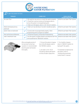
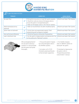
Specifications
High Capacity Settings
Model Number MXX-TN-100 MXX-TN-200
Salt Used Per Regeneration 12 lbs 24 lbs
Removal Grains 9,000 18,000
Resin Quantity - Cubic Feet 1 2
Tank Size 9" x 48 12" x 52"
Tank Jacket Yes
Brine Tank Size 15" x 17" x 36"
Service Flow Rates
Normal 8 GPM 15 GPM
Peak 10 GPM 20 GPM
Backwash Flow Rate 2 GPM 3.5 GPM
Plumbing Connections 1" or 3/4" MPT
Electrical Requirements Input 120V 60 Hz - Output 12V 650mA
Water Temperature Min 39°F - Max 100°F
Water Pressure Min 20 psi - Max 125 psi
• Continuous operation at flow rates greater than the service flow rate may affect capaci-
ty and efficiency performance.
• The manufacturer reserves the right to make product improvements which may deviate
from the specifications and descriptions stated herein, without obligation to change pre-
viously manufactured products or to note the change.
• The above capacity and flow rate specifications have not been validated by the WQA.
Need help? 1.800.608.8792 7 www.uswatersystems.com

How the Tannin Removal System Works
The principle behind Tannin removal is simple chemistry. A Tannin removal system con-
tains resin beads which hold electrically charged ions. When soft water with Tannin pass-
es through the system, Tannins are attracted to the charged resin beads. The result is re-
moval of Tannins from the water.
This system is controlled with simple, user-friendly electronics displayed on a LCD
screen. The main page displays the current time and the remaining gallons in meter
mode or the remaining days in calendar clock mode.
Need help? 1.800.608.8792 8 www.uswatersystems.com

Where to Install the System
• Place the system after sediment filtration
and the water softener. The feed water
to the Tannin removal system must be
soft.
• Place the system as close as possible to
a floor drain or other acceptable drain
point (laundry tub, sump, standpipe, etc)
• Connect the system to the main water
supply pipe BEFORE the water heater
(10' or more). DO NOT RUN HOT WA-
TER THROUGH THE SYSTEM. Temper-
ature of water passing through the sys-
tem must be less than 100°F.
• Outside faucets and irrigation sys-
tems should be supplied with hard wa-
ter prior to the system.
• Do not install the system in a place
where it could freeze. Damage caused
by freezing is not covered by the war-
ranty.
• Put the system in a place where water
damage is least likely to occur if a leak
develops. The manufacturer will not re-
pair or pay for water damage.
• A 120 volt electric outlet is needed within
6 ft of the system. The transformer has
an attached 6 foot power cable. Be sure
the electrical outlet and transformer
are in an inside location so they are
protected from wet weather.
• If installing in an outside location, you
must take the steps necessary to ensure
the system, installation plumbing, wiring,
etc are protected from the elements and
contamination sources.
• Keep the system out of direct sun-
light. The suns heat may soften and dis-
tort plastic parts.
Need help? 1.800.608.8792 9 www.uswatersystems.com


4. Use the blue funnel provided to pour the media into the tank. Pour it evenly around
the hole to ensure it is well distributed in the tank and pour slow enough to keep from
plugging the hole. A helper may be needed to hold the funnel during the filling proc-
ess. NOTE: It is recommended that a dust mask and safety goggles be worn to pre-
vent possible injury.
5. When the media is installed, move the tank side to side to settle the media. Remove
the funnel and cap from the distributor tube.
6. Lubricate the distributor O-ring and the outer tank O-ring
Need help? 1.800.608.8792 11 www.uswatersystems.com

7. Install the upper basket on the bottom of the valve by lining up the tabs then turning
the basket clockwise to lock it in place. Place the upper basket over the distributor
tube and push the valve onto the tank. Thread the valve on the tank by turning it
clockwise. Be sure not to cross thread the valve on the tank.
Need help? 1.800.608.8792 12 www.uswatersystems.com

8. Tighten the valve hand tight then snug it further by tapping it with the palm of the
hand. DO NOT use tools to tighten the valve or damage could occur.
Need help? 1.800.608.8792 13 www.uswatersystems.com

Installation Instructions
1. If your hot water tank is electric, turn off the power to it to avoid damage to the ele-
ment in the tank.
2. If you have a private well, turn the power off to the pump and then shut off the main
water shut off valve. If you have municipal water, simply shut off the main valve. Go
to a faucet or spigot (preferably on the lowest floor of the house) and turn on the cold
water until all pressure is relieved and the flow of water stops.
3. Locate the system tank and brine tank close to a drain where the system will be in-
stalled. The surface should be clean and level.
NOTE: Any solder joints being soldered near the valve must be done before con-
necting any piping to the valve. Always leave at least 6" (152 mm) between the con-
trol valve and joints being soldered when soldering pipes that are connected to the
valve. Failure to do this could cause damage to the valve.
The system is equipped with male pipe threaded ports on the control valve bypass.
The bypass is marked with arrows to show proper flow direction. The arrow pointing
toward the valve indicates the inlet. The arrow pointing away from the valve is the
outlet.
Need help? 1.800.608.8792 14 www.uswatersystems.com

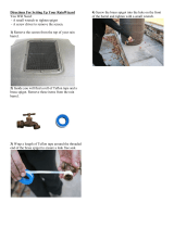
4. Insert the provided plumbing fittings into the bypass. 3/4" and 1" male pipe thread fit-
tings are supplied so ensure you pick the correct one for your plumbing. Tighten the
retaining nuts hand tight, ensuring that the fittings are not cross threaded.
Need help? 1.800.608.8792 15 www.uswatersystems.com

5. Be sure to use Teflon tape or other pipe sealant on the plumbing fitting threads and
install them on the bypass accordingly. Use an adjustable wrench to ensure they are
tight.
NOTE: All piping should be secured to prevent stress on the bypass valve and
connectors.
NOTE: Connections above are made using a stainless steel flex connector with
a rubber gasket and do not require Teflon tape.
Need help? 1.800.608.8792 16 www.uswatersystems.com


7. Connect the brine line to the control valve by removing the nut and sleeve from the
control valve. Slide the nut and sleeve over the brine line. There is a brass stiffener
pre-installed in the line.
Need help? 1.800.608.8792 18 www.uswatersystems.com

8. Push the brine line in the control valve until it stops. Then push the nut down on the
fitting and tighten it hand tight. Use an adjustable wrench to tighten the nut an addi-
tional 1/2 turn.
CAUTION: Use two wrenches to tighten the brass nut. The brass fitting must
be held while tightening the brass nut. If not, damage may occur to the valve
body.
Need help? 1.800.608.8792 19 www.uswatersystems.com

9. Now connect the brine line to the brine tank safety float assembly. Remove the brine
tank lid and the brine well cap. There is a red clip on the cap that will be used to hold
the brine line in place. Remove it, and the tape holding it, and put it to the side. Then
push the brine line through the brine tank and brine well. REMOVE the brass insert
for this connection. Push the brine line into the brine safety valve. Make sure it is
completely pushed in. Then install the red locking clip around the brine fitting be-
tween the gray collar and the brine elbow. Install the white cap on the tube.
10. Turn both bypass handles so they are perpendicular to the bypass to place the unit in
the bypass position. Slowly turn on the main water supply. At the nearest cold treated
faucet or spigot, open the faucet and let water run a few minutes or until the system
is free of any air or foreign material resulting from the plumbing work. If a faucet is
used, make sure the screen is removed first.
11. Make sure there are no leaks in the plumbing system before proceeding. Close the
water tap when water runs clean. Check for leaks again.
Need help? 1.800.608.8792 20 www.uswatersystems.com
/