Danfoss Controllers for controlling evaporators. Type AKC 114F, 115F, 116F Installation guide
- Type
- Installation guide

REFRIGERATION AND AIR CONDITIONING
ADAP-KOOL
®
Refrigeration Control Systems
Controllers for controlling evaporators
- AKC 114F, AKC 115F et AKC 116F
Function description
Refrigeration and Air Conditioning Controls

2 Function description RC.1M.F5.02 © Danfoss 08/2001 AKC 114F-116F
Validity This functional description was worked out in August 2001 and applies to the types
AKC 114F, AKC 115F and AKC 116F.
Contents
Introduction ................................................................................................................................. 3
Language .................................................................................................................................... 4
Function switch .......................................................................................................................... 4
Thermostat function ................................................................................................................... 5
Definition of thermostat function ...................................................................................... 5
Definition of thermostat sensor locations ......................................................................... 7
Night operation.................................................................................................................8
Alarm thermostat ..................................................................................................................... 10
Alarm sensor .................................................................................................................. 10
Alarm limits ..................................................................................................................... 10
Time delay ......................................................................................................................10
Door switch signal .................................................................................................................... 11
Expansion valve function ........................................................................................................12
Superheat ....................................................................................................................... 12
MOP control .................................................................................................................... 12
Forced closing ................................................................................................................ 13
TEV function ................................................................................................................... 13
Glide function ................................................................................................................. 13
Defrosting function .................................................................................................................. 14
Start of defrost ................................................................................................................14
Defrost stop ....................................................................................................................15
Start after defrost ............................................................................................................ 16
Defrost based on demand ............................................................................................. 17
Melting function .............................................................................................................. 17
Energy saving functions .......................................................................................................... 18
Fan control ...................................................................................................................... 18
Rail heat control ............................................................................................................. 18
Light control .................................................................................................................... 18
Output to compressor control ................................................................................................. 19
Sensor correction .................................................................................................................... 19
Display signal ........................................................................................................................... 19
Clock function .......................................................................................................................... 20
Access codes .......................................................................................................................... 20
Supporting text ......................................................................................................................... 20
Service ...................................................................................................................................... 21
Measurements ............................................................................................................... 21
Forced control of outputs ................................................................................................ 21
Alarms and messages ............................................................................................................ 23
Information from the controller ....................................................................................... 23
This is how the various messages are transmitted: ....................................................... 24
Who are the alarm receivers .......................................................................................... 25
Fail safe functions .................................................................................................................... 26
Injection function ............................................................................................................ 26
Thermostat function ........................................................................................................ 26
Defrost function .............................................................................................................. 26
Delayed fan start ............................................................................................................ 26
Fan stop .......................................................................................................................... 27
Plant measurement/data ......................................................................................................... 27
Operation of AKA 21 ...................................................................................................... 27
PC operation .................................................................................................................. 27
Installation considerations ..................................................................................................... 27
List of literature ........................................................................................................................ 28

AKC 114F-116F Function description RC.1M.F5.02 © Danfoss 08/2001 3
Introduction The controllers with appropriate valves and sensors are complete evaporator control systems
for refrigeration appliances and small cold rooms.
They more or less replace all other automatic controls, containing, day and night thermostats,
defrost, fan control, rail heat control, alarm functions, light control etc. The controller is
equipped with DANBUSS data communication and is operated by means of control panel type
AKA 21 and/or a PC.
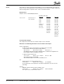
Shown in the following section is the menu selection to be made to set the functions. The
settings are indicated the way they appear in the control panel type AKA 21, e.g.
Level 1 Level 2 Level 3 (Level 4)
Defrost Control Scheduel Def.1 Start Times No. Per Day
(Number of defrosts is set)
Def1 Sc1 Def1 Sc1 Hour
(Hour value is set)
The total menu is contained in each of the following documents:
- "Menu operation via AKA 21"
- "Menu operation via AKM".
Setting of the various functions takes place via a menu system. The menu system is based on
several levels according to the following principle.
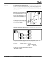
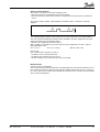
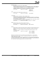
The controller’s main function is to control
the liquid injection into the evaporator. The
liquid supply is controlled by signals from
three or four temperature sensors (S1, S2
and S3/S4).
AKC 114F, AKC 115F and AKC 116F can
control the liquid injection individually on
one, two and three evaporator sections,
respectively. The sections are marked A, B
and C.
The temperature in each evaporator section
is controlled by a thermostat function which
can be defined in various ways, depending
on unit version and application.

4 Function description RC.1M.F5.02 © Danfoss 08/2001 AKC 114F-116F
Language There are three languages in the controller: English, German and French.
When the required language has been selected, the individual functions will be shown in this
language, both when there is operation via AKA 21 and system software type AKM.
NB! When you operate system software type AKM it is important that the language code is set
before an upload of the controller’s data is carried out to the AKM programme (it is the set
language that will be picked up by the AKM programme). Select one of the controller’s three
languages by means of the following settings:
0: English
1: German
2: French
Activate the selected language by pushing "Enter" and then push "Clear".
Main Function Main Function Settings Language
___
The function switch is used for stopping and starting the regulating function. The switch has
three positions:
- Regulation (Setting = +1)
- Controller stop (Setting = 0)
- Service (Setting = -1)
Main Function Main Function Settings Main Switch
+1/0/-1
If the switch is set in pos. 0 or -1, all the controller’s functions are inactive. In the menu the
“Standby mode” message is shown, when setting is selected to "0" or "-1". If the switch is in
pos. +1, regulation is started for the functions selected as “ON”.
Function switch
(Main Switch)

AKC 114F-116F Function description RC.1M.F5.02 © Danfoss 08/2001 5
The thermostat function can be defined in various ways according to the controller type and
application used. E.g., regulating principle / sensors to be used / will night setback be re-
quired, etc.
It is a requirement that each evaporator section must always be fitted with one air sensor. This
applies no matter which thermostat function is selected - even if no thermostat function is
required. It is likewise a requirement that the thermostat’s cutout temperature (“CutOut°C”) is
set at the correct air temperature, as the value is used by the injection function.
Definition of thermostat function
You may choose between three thermostat functions:
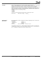
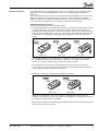
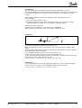
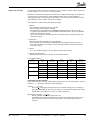
1. The thermostat function is attached to one evaporator section. AKC 114F will always control
one evaporator section only, whereas AKC 115F and AKC 116F which control several
evaporator sections may be given a master/slave function. In that case you define section A
as master section and the other sections as slave sections. The thermostat function will now
control section A, whereupon the remaining sections will follow section A’s cutins and
cutouts.
AKC 114F AKC 115F AKC 116F
The controller compares the air temperature measured in section A with the set and when
the air temperature drops to the cut-out value, refrigeration is stopped. (The expansion
valve in each section is closed, and the compressor output is cut-out).
The air temperature in section A is measured with the relevant sensor (see later). Air
sensors also have to be mounted in sections B and C (S3B and S4B), (S3/4B and S3/4C),
as the injection function uses these measurements.
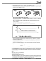
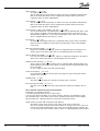
2. The thermostat function is connected to all evaporator sections
AKC 115F AKC 116F
When the air temperature in one of the sections has dropped to the cutout value, the
expansion valve will shut off this section. When the refrigeration has stopped in all sections,
the compressor output will also be stopped.
Each evaporator section is controlled by separate thermostat functions, but the cutin and cutout
values are the same for all sections.
Thermostat function

6 Function description RC.1M.F5.02 © Danfoss 08/2001 AKC 114F-116F
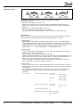
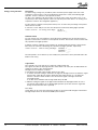
3. A Modulating thermostat function is attached to all evaporator sections
Each evaporator section can be controlled by its own modulating thermostat function (in the
two series the reference value is the same for all sections, but in series “A” separate values
may be set for the individual sections.)
- The function can only be used in central systems.
- Each individual evaporator section will be controlled separately by means of a modulating
thermostat function.
- Cutout value and differential are set as for an ON/OFF thermostat.
- The air temperature in section A (and B in AKC 115F) is measured with the attached
sensor (see later).
- AKC 115F: Air sensors S3B/S4B are used in section B
- AKC 116F: Air sensors S3/4B and S3/4C are used in sections B and C.
Principle
When products are initially cooled down and in connection with major load variations
where the temperature has been outside of the differential zone, regulation is carried out
according to the MSS principle.
At stable loads the thermostat will reduce the AKV valve’s opening time, so that the flow of
refrigerant will be limited to exactly the quantity that is needed to keep the temperature at
the required reference value.
The reference temperature will be set as the cutout temperature plus half the differential.
Settings:
Ther. Mode ___
CutOut
°
C ___
Diff.( ) K ___
Select one of the three thermostat functions by keying a figure between 0 and 3:
In all instances the
cutout temperature and differential are set as for a normal ON/OFF thermo-
stat. In other words, the differential should not be smaller than 5 K, when the thermostat sensor
is mounted behind the evaporator (S4), or 2 K, when the thermostat sensor is mounted in front
of the evaporator (S3). (If the differential is smaller, load changes may disturb the modulating
thermostat function).
Note!
With setting = 0 the following will apply:
- No thermostat function
- No pulse operation of fans
- All measured values will be updated
- Even with this setting sensors have to be mounted in all sections, if the injection function
is to work, and a temperature value (“CutOut°C”) must be set which corresponds to the
air temperature in the refrigeration appliance/cold room in question.
AKC 114F AKC 115F AKC 116F

AKC 114F-116F Function description RC.1M.F5.02 © Danfoss 08/2001 7
All thermostat sensors must be mounted. If a sensor has not been mounted or is cut- out or
shortcircuited, this will result in the error message “Sensor error” and an alarm on the alarm
output.
Overriding
The thermostat function has been prepared for overriding from a master control unit.
The offset value will be transmitted from the master control unit to the controller via DANBUSS.
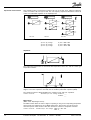
Definition of thermostat sensor locations
When the required number of thermostats per controller has been selected, it must be
established where the individual sensors are to be placed.
There are three possible locations (1, 2 and 3), where the sensors are placed in the air right in
the evaporator inlet, in the evaporator outlet, or both before and after the evaporator:
1) Sensor is placed in the return air to the evaporator.
2) The sensor is placed in the outlet air from the evaporator.
3) Two sensors are mounted. One on either side of the evaporator (weighted control).
In AKC 116F this placing should only be used for thermostat function 1.
The measured values are weighted with a percentage of S3 (air inlet) and a percentage of
S4 (air outlet).
Example:
S4 measures -25°C and S3 measures -20°C.
Required as regulation parameter is a weighted average consisting of 60% S4 and the rest
from S3 (only the S4 share is programmed). This gives a regulating value of på 0.6 x -25°C
+ 0.4 x -20°C = -23°C
When placed like this, the S4 sensor's influence must be set, i.e. S4 Day % (S3 is weighted
automatically). During night operation the influence may be different.
S4 Day % ___
S4 Night % ___

8 Function description RC.1M.F5.02 © Danfoss 08/2001 AKC 114F-116F
AKC 114F and AKC 115F
As a result of the weighting, a minimum value may be entered for the S4 temperature.
If the S4 temperature becomes lower than the minimum value, the refrigeration will be
stopped and the alarm activated. When the temperature rises to 2 K above the minimum
value, refrigeration will start again and the alarm will be cancelled.
S4 MinLim
°
C ___
Define the selected sensor placing with settings 1, 2 or 3:
Ther. Sx ___
Night operation
Change between day and night operation can be accomplished by means of an external
signal or by means of a time schedule in the controller, or with a signal from the master control
unit. (The function is independent of the thermostat function).
External signal
A signal connected to input “S6”.
The input registers the resistance value of the connected sensor / contact function.
(A resistance value greater than 1400 ohm will give night operation, a resistance value
smaller than 1100 ohm will give day operation).
A light-sensitive sensor placed in the refrigeration appliance may be used as signal
transmitter.
The function can also be obtained by connecting an external relay.
A shortcircuited S6 input will give day operation.
The relay contact must be goldplated.
Internal time schedule
It is also possible to use an internal time schedule, where the system is to change between
day and night operation.
The start and stop times are set for each day of the week.
Principle
Definitions
Night: The moment when night operation starts
Day: The moment when night operation stops

AKC 114F-116F Function description RC.1M.F5.02 © Danfoss 08/2001 9
Night = 0 or Day = 0:
When one of the two times is set at 0, or when both are set at 0, there will be no night
operation for that particular 24-hour period.
Night = 1 and Day = 1:
When the two settings are set to the same time, there will be night operation during the
entire 24-hour period.
Settings:
Common Controller Day/Night Ctrl. Settings Mo day h ___
Mo night h ___
Tu day h ___
Tu night h ___
etc.
Signal from a master control unit
A signal from a master control unit may be received via DANBUSS.
When the signal is received, there is change-over to night operation.
Change-over to night operation is defined, as follows:
Day / Night =
0: No night setback
1: Night operation according to signal at S6 input
2: Night operation according to internal time clock
3: Night operation according to signal from a master control unit.
Common Controller Day/Night Ctrl.Settings Day/Night
___
Dt Night K ___

10 Function description RC.1M.F5.02 © Danfoss 08/2001 AKC 114F-116F
Alarm thermostat The function is used for sounding the alarm before the product temperature at the refrigeration
site becomes critical.
You can set alarm limits and time delays for high and low temperatures. Alarm will be given if
the set limit is exceeded, but not until the time delay has expired.
The alarm sensor may be chosen independently of the sensor used for the thermostat
function.
The alarm function is a genuine alarm function, and it will not affect the AKV valve's opening/
closing routine
Alarm sensor
AKC 114F: Select either alarm sensor S3A or S4A
AKC 115F: A-section: S3A or S4A
B-section: Follow the setting for section A
AKC 116F: A-section: S3A or S4A
B-section: S3/4B
C-section: S3/4C
The alarm thermostat is activated, and the alarm sensor for section A is defined by keying a
figure between 0 and 3 in the function "Alarm Mode":
0: Alarm thermostat not operating
1: S3A is used
2: S4A is used
3: (AKC 114F and AKC 115F only). Thermostat temperature section A is used.
Alarm limits
The alarm limits apply to all the sections.
The required temperature is indicated in °C.
HighLim
°
C
___
Low Lim
°
C
___
The high-temperature limit will however be raised in the following situations:
· During night operation by the "night setback" value
· If a signal arrives from the master control unit via DANBUSS:
- the thermostat function will be overridden (peak load function)
- the alarm limit will be raised (extremely hot summer day).
Time delay
Three time delays are set for alarms:
For too high temperature:
High1Del m: Time delay after activation of the ON input,
time delay following defrost,
time delay after a power failure
The time delay will apply until the actual air temperature has dropped
below the "upper alarm limit".
High2Del m: Time delay during normal regulation
For too low temperature:
Low Del m: After the time delay the alarm will sound.
The time delay is indicated in minutes:
High1Del m ___
High2Del m ___
Low Del m ___

AKC 114F-116F Function description RC.1M.F5.02 © Danfoss 08/2001 11
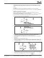
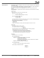
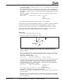
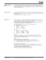
Example
IN: Thermostat cut-in value
OUT: Thermostat cut-out value
Lim: Alarm limit for high temperature and low temperature
S: Alarm ceases
Curve 1: Cooling stage
(1): Time delay "High1Del m" has been exceeded. Alarm becomes active.
Curve 2: Normal regulation where the temperature becomes too high.
(2): Time delay "High2Del m" has been exceeded. Alarm becomes active.
Curve 3: Temperature becomes too low
(3): Time delay "Low Del m" has been exceeded. Alarm becomes active.
AKC 114F only
The controller is provided with a digital input that may be used for monitoring a door switch.
When the input registers that the door switch is open, the light output will change to ON at the
same time as the expansion valve will close and the fans will stop. There are two things the
function can be used for:
1: If the temperature reference is set at less than -10°C.
2: If the temperature is registered at less than -10°C. (If the temperature becomes higher than
-10°C, the function will be cut out again).
(0: The function is not used).
The controller constantly registers the time the door switch is open. This time is all the time
added up and saved in two registers: 1 - present opening time during the actual full hour and 2
-the opening time during the previous full hour. This aggregate time (1 + 2) is related to the
allowed opening time, and if the time is exceeded, the alarm will sound. The alarm will stop
again, when the aggregate time becomes less than the allowed time (at the next hour change,
at the earliest).
Setting
Common Controller Door switch settings DoorAction
0/2
Open Time
0 - 120
By means of AKM system software the following parameters can be displayed:
- the aggregate opening time during the previous full hour (updated at hour change)
- number of openings during the previous full hour.
Door switch signal

12 Function description RC.1M.F5.02 © Danfoss 08/2001 AKC 114F-116F
Expansion valve function One expansion valve is connected to an AKC 114F, two to an AKC 115F, and three expansion
valves to an AKC 116F. The type is AKV 10-n. The capacity requirement determines which. All
valves have individual regulation of the liquid injection.
Select ON or OFF for the injection functions for the individual sections A, B and C.
Injection (A) Settings Inj. Ctrl. A
OFF / ON
Injection (B) Settings Inj. Ctrl. B
OFF / ON
Injection (C) Settings Inj. Ctrl. C
OFF / ON
Superheat
The evaporating temperature is measured with temperature sensor S1, and the suction gas
temperature with S2.
The function contains an adaptive algorithm that independently adjusts the valve’s opening
degree, so that the evaporator constantly has the smallest permissible superheat (MSS).
The superheat reference will be limited by the settings for min. and max. superheat.
Common Controller Extended Inject. Ctrl. Settings SH Max K
___
SH Min K
___
MOP control
(MOP = Max. Operating Pressure)
The MOP function limits the valve’s degree of opening as long as the evaporating temperature
measured by S1 is higher than the set MOP temperature. The function can only be active
when the injection valve function is ON. This function is common to all injection functions.
Common Controller Extended inject. Ctrl. Settings MOP Ctrl.
OFF / ON
MOP
°
C ___
AKC 114F AKC115F AKC 116F

AKC 114F-116F Function description RC.1M.F5.02 © Danfoss 08/2001 13
Forced closing
The AKV valves can be closed with an external signal (the “ON” input is cut-out).
The function must be used in connection with the compressor’s safety circuit, so that there will
be no injection of liquid into the evaporator when the compressor is stopped by the safety
controls.
Defined with the following setting is what will happen when the ON input is cut out.
0: No overriding
1: Valve closes and compressor stops
2: All outputs change to pos. OFF, but the light output remains in pos. ON. (This setting is
recommended when a module has to be stopped, e.g. during cleaning).
Signal from a master control unit
A signal can be received from a master control unit via DANBUSS.
When the signal is received, the valve closes and the compressor stops.
TEV function
The electronic injection function may be cut out. The injection function can then be carried out
by means of a thermostatic expansion valve (like type TE).
When this application is used, a solenoid valve must be connected to the controller’s AKV
output.
The thermostat function will now control the solenoid valve ON and OFF, so that the required
media temperature will be maintained.
It is a requirement that the solenoid valve’s coil is a 230 V d.c. coil.
(In AKC 114F the compressor output is used, if the required coil is a.c.).
The function is defined by putting the expansion valve function “Inj.Ctrl.()” in pos. OFF (see the
previous page) and the “TEV” function in pos. ON.
Common Controller Extended Inject. Ctrl. Settings TEV
OFF / ON
Glide function
If a zeotrope refrigerant is used in the refrigeration appliance, a value for temperature glide
must be set. You are welcome to consult DANFOSS about the correct setting.
Common Controller Extended Inject. Ctrl. Settings Glide K ___

14 Function description RC.1M.F5.02 © Danfoss 08/2001 AKC 114F-116F
Defrosting function
The defrost form is electrical or manual and can be defined, as follows:
0: No defrost function
1: All sections start defrost at the same time
Defrost stop is common, when it is based on time, but individual, when it is based on
temperature. Cooling will not be resumed, until all sections have concluded their defrost
cycles.
2: The sections are defrosted in sequence (A®B®C)
(there is cooling on the sections that are not defrosted)
The fans cannot be stopped during defrost, and there can be no delayed fan start.
Start of defrost
Defrost can be started in four ways (they may be started at random). When defrost has been
started, the defrost cycle will continue until a “Defrost Stop” signal is received.
1. Manual defrost
Manual defrost is started from control panel type AKA 21 or a PC. The setting will itself
change back to OFF, when cooling is resumed after defrost. Each of the sections can be
started individually (in AKC 115F and 116F, however, also simultaneously). If defrost is only
started in one of the sections, the fans will be operating during the defrost cycle).
Defrost Control Defrost Start Method Man. Def.
OFF / ON
2. External signal
Defrost is started with a 230 V signal on terminals 30/31. The signal must be an impulse
signal of at least two seconds’ duration.
Defrost will start, when a signal is received on the input.
A period of at least 60 minutes has to elapse from the end of a defrost period before a new
defrost with “external signal” can be started. (If defrost is required within the 60 minutes, a
defrost cycle can be started with one of the other defrost start signals).
If the external signal is still active 30 minutes after cooling is resumed, there will be an
alarm. The alarm ceases when the signal is removed.
3. Internal clock
Defrost is started by means of a weekly programme that is set in the controller. The times
have relation to the controller’s clock function. Defrost will start, when a signal is received
from the table.
Three individual schedules with up to eight defrosts per schedule can be programmed.
Subsequently, the individual week days can be defined to follow one of the three
schedules.
Defrost Control Schedule 1 Def.Start Times No. Per Day ___
Def1 Sc1 Def1 Sc1 Hour ___
Def1 Sc1 Min ___
Def2 Sc1 Def2 Sc1 Hour ___
Def2 Sc1 Min ___
etc.
Schedule 2Def.Start Times No. Per Day ___
Def1 Sc2 Def1 Sc2 Hour ___
etc.
Schedule 3Def.Start Times etc.
Extended Program Schedules Mon. Sched.
1/2/3
___
Tue. Sched.
1/2/3
___
etc.

AKC 114F-116F Function description RC.1M.F5.02 © Danfoss 08/2001 15
The controller contains an auxiliary function that can be used for filling in the defrost periods
in the three schedules.
Key in the number of defrosts, the starting time for the first defrost, and the starting time for
the last defrost. If you put “Auto Set” in pos. ON, the auxiliary function itself will distribute the
given number of defrosts evenly over the period and enter the calculated times in the three
schedules.
(If the three schedules cannot be identical, the values of the deviating schedule must be
entered separately).
Defrost Control Extended Program Schedules No. Per Day ___
FirstDef ___
LastDef ___
Auto Set
OFF / ON
In connection with forced closing, the defrost is subject to some limitations:
If the function of the outputs ("ON-InpMode") is defined as 1 and there is forced closing, defrost
may still be started with one of the three above mentioned signals. If a defrost cycle is in
progress, the forced closing status will not be re-established until the defrost is completed.
If the function of the outputs ("ON-InpMode") is defined as 2 and there is forced closing, a
defrost cycle cannot start. If a defrost is in progress, it will be stopped.
Defrost stop
You may choose between two kinds of defrost stop.
1. Stop based on temperature and with time as security
Here the evaporator’s temperature is measured with sensor. When this temperature is
equal to or higher than the temperature set for defrost stop, the defrost will stop in the
section in question.
When there is electric defrost, S5 is normally selected as defrost sensor, but S3 or S4 may
also be selected (S3 is an air sensor placed in the evaporator inlet, and S4 is an air sensor
placed in the evaporator outlet).
Select sensor type with setting 1-5, (5=S5):
Defrost Control Defrost Stop.Temp(1)/Time(2) DefStop Sx
1/2/3/4/5
If the defrost time exceeds the set max. defrost time, the defrost stops. This will happen even
if the defrost stop temperature has not been reached (max. defrost time will function as
safeguard). When the defrost is stopped on time, the alarm message “Max. def. period
exceeded” will appear for the section in question. If the alarm is not acknowledged within
five minutes, it will automatically be cancelled.
Defrost Control Defrost StopTemp(1)/Time(2) Temp/Time
1 / 2
MaxDefTime ___
Def. Stop
°
C ___
Select "Stop on temperature and time as security" by putting "Temp/Time" = 1.
"MaxDefTime" is the setting of max. defrost time in minutes.
"Def. Stop °C" is the setting of the temperature at the selected defrost sensor, when defrost
has to be stopped.
When there is an error in a defrost sensor, an alarm appears and the defrost stop will then
be based on time in the relevant section. Defrost stop for the remaining sections will still be
based on temperature.

16 Function description RC.1M.F5.02 © Danfoss 08/2001 AKC 114F-116F
2. Stop based on time
A fixed defrost time is set here. When this time has elapsed, the defrost will be stopped and
cooling will be resumed. (When stop on time the controllers does not check whether one or
more of the evaporators still require defrost.
Defrost Control Defrost StopTemp(1)/Time(2) Temp/Time
1 / 2
MaxDefTime ___
Select "Stop based on time" by setting "Temp/Time" in position 2
"MaxDefTime" is the setting of defrost time in minutes.
A defrost in progress can be stopped manually by setting “Def. Ctrl” in pos. OFF for a moment,
or “Main Switch” in pos. 0.
Start after defrost
After a defrost it is possible to start the unit with a time delay for the liquid injection and the fan
operation, respectively.
a. Delayed liquid injection
The time delay is set in minutes (0 min., if applicable).
Defrost Control Defrost Sequence Settings Inj.Del m ___
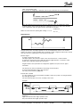
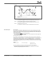
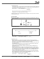
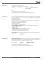
b. Delayed fan start
Drops of water left on an evaporator after defrost should be bound to the evaporator
(primarily used in freezing rooms). The function is only active, if the definition of the defrost
has been set at 1 (i.e. all sections will be defrosted at the same time).
After defrost, the liquid injection is started, the evaporator is cooled down, but the fans will
be started a little later.
The temperature at which the fans are to be started is set (measured always with the S5
sensors). The max. permissible time delay in minutes is set.
The time delay for fan start will not commence until the time delay for liquid injection, if
applicable, has run out.
Only when all the S5 sensors register a lower temperature than the set will the fans be
started. If all S5 sensors do not register a lower temperature than the set by the delay time
has elapsed, the fans will start. At the same time alarm is given that Maximum delaytime for
fan is exceeded for the section in question. If the alarm is not acknowledged within five
minutes, it will automatically be cancelled.
If some of the S5 sensors are defective, the signal from sensors that remain intact will be
used. If all S5 sensors are defective, the fans will start immediately upon expiry of the time
delay for liquid injection, if such a function has been included.
The time delay is set in minutes (0 min., if applicable).
Defrost Control Defrost Sequence Settings Fan OnDel m ___
Fan On
°
C
___
Defrost Liquid injection
is delayed
e.g. 20 min. e.g. 2 min.
Example

AKC 114F-116F Function description RC.1M.F5.02 © Danfoss 08/2001 17
Defrost based on demand
The function can only be used in the following context:
- defrost start must be made with the internal clock function
- defrost stop must be performed on the basis of temperature measurements by the defined
sensor
The function checks whether a planned defrost should be made, or whether it should be
skipped.
The controller gathers internal control values that are then analysed at each planned defrost
start. The analysis will determine whether defrost should be started or skipped. The analysis
will be repeated for the next planned defrost.
A defrost is only skipped if all sections allow it.
With a setting you can indicate how many defrosts may be skipped in succession, before a
defrost has to be made.
Defrost Control Defrost Ctrl. Settings DOD Ctrl.
OFF / ON
Please note
The controller will not function correctly, if:
- the defrost sensor is placed incorrectly
- the defrost stop value has been set too low
- the time setting for max. defrost time has been set too high
Melting function
(only for control of refrigeration)
The function will ensure that the evaporator is not blocked by frost. This function operates once an
hour, and the frost that has settled on the evaporator will then melt to water (or to ice, if there is a
lot of frost). This ensures a better air flow through the evaporator at the same time as the insulating
effect of the frost disappears.

18 Function description RC.1M.F5.02 © Danfoss 08/2001 AKC 114F-116F
Energy saving functions Fan control
To obtain energy savings it is possible to pulse control the power supply to the fans at the
evaporators. This function is only active during the thermostat’s cutout period during night
operation, and it is common to all evaporator sections.
For AKC 115F and AKC 116F the function can only be active, when all sections are in a cut-
out period. (In other words, impulse control can only take place when there is no cooling of an
evaporator section in the refrigeration appliance).
If pulse control is required, set the period “FanCycl m” as well as the percentage of the period
where the fans are ON.
If "Fan On" is set to 100 per cent, the fans will operate continuously during night operation.
Common Controller Fan Pulsing (Cutout Night) Fan On % ___
FanCycl. m ___
Rail heat control
To save energy costs it is possible to control the power supplied to the rail heat by means of
impulses. The function is common to all evaporator sections. The function can be used for both
day operation and night operation.
If impulse control is required, set the “RailCycl m” period and the percentage of the period of
time where the rail heat is ON during day operation and night operation, respectively.
Common Controller Railheat Pulsing (Day/Night) RailOnDay %
____
RailOnNgt %
____
RailCycl m
____
The time period is set in minutes (a short “RailCycl m” period and a heavy load will reduce the
lifetime of the relay).
Light control
The controller can cut in and cut out a signal for a light control unit.
The signal can follow the day/night function, and for AKC 114F it may also be defined that the
signal has to follow a door switch function.
The light control is defined, as follows:
0: No signal for the light control (output always in pos. OFF)
1: In an AKC 114F this setting is selected, if the signal for the light control is to follow the signal
from the door switch (do not forget to define the door switch function as 1 to obtain the
function. If the door switch function is not selected, the signal to the light control will
constantly be ON).
In an AKC 115F and AKC 116F the signal will always be ON.
2: With this setting the signal for the light control will follow the day/night function in such a
way that the signal will be cut out during night operation (in an AKC 114F the signal will
change to ON, when the door is opened).
Time delay
A time delay can be set for the period from the door is closed and until the light is switched off.
The light output status can be read via AKM system software.

AKC 114F-116F Function description RC.1M.F5.02 © Danfoss 08/2001 19
The controller has an output that can be used for compressor control. The output will follow the
status of the thermostat function, so the output will be cut out when the thermostat does not
require refrigeration. If the thermostat function has been selected in pos. OFF, the compressor
output will constantly be ON.
Output to compressor
control
Sensor correction The input signal from all connected sensors can be corrected. A correction will only be necessary
if the sensor cable is long and has a small cross-sectional area. All displays and functions will reflect
the corrected value.
Settings must be performed via AKM system software.
The air temperature measured at the evaporator can be read on a display. It must be an LCD
display type AKA 14. The display is normally fitted to the appliance, so that the customer can
see the air temperature. A display can be mounted in each section.
The temperature display can be selected independently of the selected thermostat function.
If setting 0 is selected, the display will show three dashes “- - -”.
The following setting will determine the sensor values to be displayed:
AKC 114F / AKC 115F
0: The display will show three dashes "---"
1: A: S3A B: S3B
2: A: S4A B: S4B
3: A: "Ther.Air A" B: "Ther.AirB"
AKC 116F
0: The display will show three dashes "---"
1: A: S3A B: S3/4B C: S3/4C
2: A: S4A B: S3/4B C: S3/4C
3: A: "Ther.Air A" B: S3/4B C: S3/4C
Section A
If setting 3 is selected, S3(A) and S4(A) will be included with the weighting set under the
thermostat function (if no thermostat function has been selected, the displayed value will
originate from the defined sensor (S3 or S4)).
Codes
The display can show you the following codes:
"dEF" : Appears during defrost, and 15 minutes after the end of the defrost.
"AL1" : Appears when there are errors in sensors attached to the display function.
"- - -" : Appears if the display function is not active.
Displacement of the displayed value
The values shown on the display can be offset-adjusted individually for each section. The
function is used where it is required that the display is calibrated to show the measured air
temperature surrounding the refrigerated products.
The displacement is indicated in degrees with a decimal.
The function can only be set via system software type AKM.
Display signal

20 Function description RC.1M.F5.02 © Danfoss 08/2001 AKC 114F-116F
The controller contains a clock function.
Settings have to be made of days, hours and minutes.
AKC --- Adr. Clock Clock: Day
1-7 (1=Monday, 7=Sunday)
Clock : Hour
0-23
Clock: Min.
0-59
Note:
The clock has to be reset after a power failure.
If the controller is connected to an installation with gateway type AKA 244.
The controller can be operated with system software type AKM and control panel type AKA 21.
Both operating modes may give access to several levels, depending on the user’s knowledge
of the various functions.
System software type AKM:
The different users are defined here with initials and passwords. Access is now granted to
exactly the functions the user is allowed to operate.
The operation is described in the AKM manual.
Control panel type AKA 21:
Access can be given to three user levels here:
1) Access without use of password.
See alarms. Display selected temperatures. Change temperature in the refrigeration
appliance. Start defrost.
2) Access via code 1
Setting of selected functions, acknowledgement of alarms.
3) Access via code 2
All settings in the menu system can be performed.
The operation is described in “Menu operation via AKA 21”.
If access code is set in pos. “0” (factory setting), there is free access to the system without the
use of a password.
AKC --- Adr. Chg. Code1
___
Chg. Code 2
___
When the controller is set from control panel type AKA 21, it is possible to show auxiliary text in
the display for a few functions.
This is done by pushing the key “Help” when the required function is shown in the display. A
brief text will now appear which describes the setting. For example:
Function is shown
Push "Help"
Auxiliary line 1 appears
Push "¯"
Auxiliary line 2 appears
etc.
Finish by pushing "¬", and you will return to the function.
In the menu is shown which functions are provided with auxiliary text.
Clock function
Access codes
Supporting text
Page is loading ...
Page is loading ...
Page is loading ...
Page is loading ...
Page is loading ...
Page is loading ...
Page is loading ...
Page is loading ...
-
 1
1
-
 2
2
-
 3
3
-
 4
4
-
 5
5
-
 6
6
-
 7
7
-
 8
8
-
 9
9
-
 10
10
-
 11
11
-
 12
12
-
 13
13
-
 14
14
-
 15
15
-
 16
16
-
 17
17
-
 18
18
-
 19
19
-
 20
20
-
 21
21
-
 22
22
-
 23
23
-
 24
24
-
 25
25
-
 26
26
-
 27
27
-
 28
28


Danfoss Controllers for controlling evaporators. Type AKC 114F, 115F, 116F Installation guide
- Type
- Installation guide
Ask a question and I''ll find the answer in the document
Finding information in a document is now easier with AI
Related papers
-
Danfoss Controllers type AKC 14, AKC 15 and AKC 16 for evaporator control vers. 1.2x Installation guide
-
-
-
-
-
-
-
-
-