Electric Controller & Mfg. (EC&M) DC Magnetic Contactor - Class 7004 Type MGO3, 300A, SPNC, Size NEMA5, Series A Installation guide
- Type
- Installation guide

Instruction Bulletin
Bulletin No. 50006-369-10
February 1998
Raleigh, NC, USA
Replaces 7004-70 dated 4/78
Single-Pole DC Contactor, Normally Closed
Size 5, 300 A, Type MGO-3, Series A
Class 7004
© 1998 Square D All Rights Reserved
1
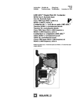
This instruction bulletin illustrates and describes the Class 7004, MGO-3 single-pole DC
contactor. The Class 7004, Type M contactor is a DC magnetic, mill-type clapper device
designed to meet NEMA Standards. Table 1 lists the contactor ratings.
The operating coils are designed in accordance with NEMA standards to withstand 110% of
rated voltage continuously and to operate the contactor successfully at 80% of rated voltage.
Standard coil voltages are 115/120 VDC and 230/240 VDC. Table 2 lists the ratings for
standard operating coils. For other available coil voltages, refer to Class 9998 Coil Data
Catalog Sheet.
Electrical interlocks consist of stationary contacts mounted on the contact-arm support (item
23) and moving contacts attached to the bottom of the contact-arm assembly (item 22). A set
of electrical interlocks contains one normally-open and one normally-closed double break
contact. Make and break ratings apply for double-throw contacts only when both the normally-
open and normally-closed contacts are connected to the same polarity. The electrical interlock
ratings, listed in Table 3 and Table 4, are in accordance with NEMA standard ICS-2-125 (A600
and N600 Table Ratings).
Table 1: Maximum Contactor Ratings @ 600 VDC +40
°
C Ambient
Size Ratings DC Motor Horsepower
@ 230 VDC DC Amperes
Size 5, 300 A Open 8-hour 75 300
Enclosed 67 270
Crane 110 400
Table 2: Operating Coil Ratings
Coil Part Number DC Voltage Rating Nominal Resistance
@ +20
°
C (
Ω
)Coil Amperes
@ 20
°
C
D51017-243-53 230/240 1220 .197
D51017-243-56 115/120 310 .380
Table 3: Electrical Interlock AC Ratings (A600)
Volts Maximum Current (A) Maximum Continuous
Current (A)
Make Break
120 60 6.0 10
240 30 3.0 10
480 15 1.5 10
600 12 1.2 10
HAZARDOUS VOLTAGE
Disconnect all power before working on equipment.
Failure to observe this precaution will result in death or serious injury.
DANGER
!
INTRODUCTION
Contactor Ratings
Operating Coils
Electrical Interlocks

Single-Pole DC Contactors, Normally Closed Bulletin No. 50006-369-10
Installation February 1998
2
©
1998 Square D All Rights Reserved
The movable and stationary power contact tips are identical. Copper power contact tips are
standard. Silver-faced power contact tips are available and are recommended for
applications where the contactors remain closed for long periods of time. Silver-faced
contact tips are standard on crane manual magnetic disconnect switches and are optional
on DC starters.
1. Unpack contactor carefully. Remove shipping tape, if used.
2. Inspect nameplate data for correct equipment. Visually verify that the contactor
operating coil (item 36) is the correct voltage. The operating coil circuit voltage may be
different than the power circuit voltage.
3. Visually verify that all parts are undamaged and secure.
4. Mount the contactor vertically on a rigid support and fasten it down tightly using a plain
washer against the contactor base. Provide the clearances shown in Figure 1 on page
3 above the top of the contactor and in front of the arc chute for pivoting or removal of
the arc chute and for electrical clearances.
5. With all power removed, mount auxiliary devices such as electrical interlocks, if used,
on contactor. Install and adjust these auxiliary devices according to procedures in the
instruction sheets provided with the devices.
6. With all power removed, pivot the arc chute upwards. The contact tips (item 10) should
meet squarely. If they do not meet squarely, align them by the procedure in “Contact
Tip Alignment” on page 4.
Table 4: Electrical Interlock DC Ratings (N600)
Volts Maximum Current (A) Maximum Continuous
Current (A)
Make Break
125 2.2 2.2 10
250 1.1 1.1 10
600 0.4 0.4 10
Contact Tips
INSTALLATION
HAZARDOUS VOLTAGE
Disconnect power to contactor before installation, adjustments, maintenance or
troubleshooting. Metal parts of contactor may be at line voltage.
Failure to observe this precaution will result in death or serious injury
DANGER
!
IMPROPER CONNECTION HAZARD
Failure to connect operating coil to proper voltage may cause improper contactor
operation or damage to coil.
Failure to observe this precaution can result in injury or product damage.
CAUTION

Bulletin No. 50006-369-10 Single-Pole DC Contactors, Normally Closed
February 1998 Installation
3
©
1998 Square D All Rights Reserved
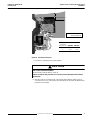
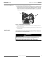
Figure 1: Electrical Clearances
7. Pivot the arc chute down to its proper position.
8. Wire the contactor according to the control panel wiring diagram, making sure all
connections are secure. The voltage of the operating coil circuit may be different than
the power circuit voltage.
Y
Note: Shaded area for
arcing clearances.
Dimension
to grounded,
uninsulated panel 600 VDC 240 VDC
X 2.037'' 2.037''
Y 6.0'' 2.8''
X
ARC CHUTE POSITION HAZARD
Do not operate contactor with arc chute up.
Failure to observe this precaution can result in product damage and shortened
product life.
CAUTION

Single-Pole DC Contactors, Normally Closed Bulletin No. 50006-369-10
Adjustments February 1998
4
©
1998 Square D All Rights Reserved
Contactors may require contact alignment or adjustment of the electrical interlocks. This
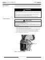
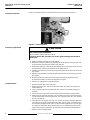
section describes the adjustment procedures. Refer to Figure 2 when aligning the contact tip.
1. Remove all power. Pivot arc chute upward.
2. Visually verify that movable contact tip (item 10) is properly seated against the ridge
located on the auxiliary arm (item 14). See Figure 2.
3. Visually verify that stationary contact tip (item 10) is seated against the stationary
contact support located on the blowout coil assembly (item 2). See Figure 2.
4. Visually verify that contact tip surfaces are vertically and horizontally aligned.
5. Pivot arc chute down to its proper position.
Figure 2: Contact Arm Assembly
ADJUSTMENTS
HAZARDOUS VOLTAGE
Contactors operated under load expel an arc. Stay away from contactor operated under
load.
Disconnect power to contactor before aligning contact tips or adjusting electrical
interlock. Metal parts of contactor may be at line voltage.
Failure to observe these precautions will result in death or serious injury.
DANGER
!
Contact Tip Alignment
ARC CHUTE POSITION HAZARD
Do not operate contactor with arc chute up.
Failure to observe this precaution can result in product damage and shortened
product life.
CAUTION
14
2
10

Bulletin No. 50006-369-10 Single-Pole DC Contactors, Normally Closed
February 1998 Maintenance
5
©
1998 Square D All Rights Reserved
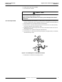
Refer to Figure 3 when adjusting the electrical interlock.
1. Remove all power. Visually verify that electrical interlock assembly (item 46) has proper
follow-up (amount of spring compression). With new electrical interlock contacts, the
moving contacts (item 49) should provide at least 1/16'' follow-up on each stationary
contact when the contact arm reaches its limit of travel, either completely closed or
completely opened (see Figure 3).
Figure 3: Electrical Interlock Contact Follow-Up
2. Visually verify that the power contact tips open before the normally-open electrical
interlock contacts close.
3. Electrical interlock follow-up can be adjusted by bending stationary contacts (items 53
not shown and 54).
This section describes some of the maintenance procedures that may be required for the
Class 7004 Type MG0-3 contactor. No lubrication is required since these contactors have
permanently-lubricated, oil-impregnated bearings.
Electrical Interlock Adjustment
49
54
MAINTENANCE
HAZARDOUS VOLTAGE
Disconnect power to contactor before installation, adjustments, maintenance or
troubleshooting. Metal parts of contactor may be at line voltage.
Failure to observe this precaution will result in death or serious injury.
DANGER
!

Single-Pole DC Contactors, Normally Closed Bulletin No. 50006-369-10
Maintenance February 1998
6
©
1998 Square D All Rights Reserved
Replace contact tips when the contact follow-up is less than 1/16'' (see Figure 4).
Figure 4: Contact Follow-Up
1. Remove all power. Pivot the arc chute upward.
2. Remove the movable contact tip by removing the silicon bronze hex head cap screw
and lock washer located on the auxiliary arm (item 14).
3. Remove the stationary contact tip by removing the silicon bronze hex head cap screw
and lock washer located on the blowout coil assembly (item 2).
4. Install the new stationary contact tip using the silicon bronze hex head cap screw and
lock washer.
5. Install the new movable contact tip using the silicon bronze hex head cap screw and
lock washer.
6. Manually operate the contactor and check the contact tips for alignment by the
procedure described in "Contact Tip Alignment" on page 4.
7. Pivot the arc chute down to its proper position.
1. Remove all power. Disconnect coil leads.
2. Remove hex head cap screws and lock washer (items 41 and 8) from contact arm
support (item 23).
3. Lower complete contact arm support and main contact arm assembly (support as
required).
4. Loosen hex head cap screws and lock washer (items 43 and 8) on magnet frame.
5. Remove the silicon bronze hex head cap screw (item 11) on the front of the magnet
core and remove the lock washer (item 13), core cap spacer (item 34), core cap (item
35) and coil (item 36).
6. Install the new coil using the core cap, core cap spacer and lock washer. Tighten the
silicon bronze hex head screw. Note that the steel core cap, which is thicker than the
non-magnetic phosphor bronze spacer, must be installed against the coil (see Figure
6 on page 11). Ensure the spring washer (item 37) is so positioned that the outside
edge (concave side) is against the coil (item 36) and not against the magnet frame.
7. Tighten screws on magnet frame.
Contact Tip Inspection
ARC CHUTE POSITION HAZARD
Do not operate contactor with arc chute up.
Failure to observe this precaution can result in product damage and shortened
product life.
CAUTION
Contact Tip Replacement
Coil Replacement

Bulletin No. 50006-369-10 Single-Pole DC Contactors, Normally Closed
February 1998 Maintenance
7
©
1998 Square D All Rights Reserved
8. Replace the contact arm assembly.
9. Reconnect the coil leads.
1. Remove all power. Disconnect the arc chute wires by removing the hex head cap screw
(item 42), washer (item 19), lock washer (item 8), arc chute wires and shunt (item 21).
2. Disassemble the arc chute wires from the contactor base.
3. Remove the arc chute by removing the hex head nut (item 12), lock washer (item 8),
hex head screw (item 40), and the arc chute.
4. Install the new arc chute using the hex head cap screw and lock washer and secure
with the hex head nut.
5. Reposition the arc chute wires along the contactor base.
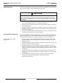
6. Reconnect the arc chute wires and shunt (see Figure 5) using the washer, lock washer,
and hex head cap screw.
Figure 5: Assembling the Arc Chute Wire and Shunt
7. Rotate the arc chute back to its proper position.
ARC CHUTE POSIITON HAZARD
Do not operate contactor with arc chute up.
Failure to observe this precaution can result in product damage and shortened
product life.
CAUTION
Arc Chute Replacement
19
21
8
42
23

Single-Pole DC Contactors, Normally Closed Bulletin No. 50006-369-10
Maintenance February 1998
8
©
1998 Square D All Rights Reserved
Replace the shunt (item 21) when the flexible braided wires are broken or burned or if wires
are loose in the terminal connectors at either end of the shunt.
1. Remove all power. Disconnect bottom end of shunt (item 21) by removing the hex head
cap screw, lock washer, washer, arc chute wires and the shunt.
2. Disconnect the top end of shunt (item 21) by removing the hex head nut, lock washer,
washer and the shunt.
3. Ensure the auxiliary arm pin (item 27) is centered and the set screw (item 18) is tight.
4. Install the new shunt. Connect the top end of the shunt by replacing the washer, lock
washer, and hex head nut.
5. Connect the bottom end of the shunt by replacing the shunt, arc chute wires, washer,
lock washer and hex head cap screw (see Figure 5).
The electrical interlock contact tips should be replaced when inspection shows that they are
burned or badly pitted. It is recommended that the entire electrical interlock assembly be
replaced from a kit. However, the contact tip assemblies only can also be replaced.
1. Remove all power. Loosen terminal clamps and screws and remove terminal leads
from the stationary contact assembly. Note the position of the leads so they can be
properly replaced.
2. Remove the movable contact assembly by removing the slotted screws (item 47), lock
washers (item 48) and washers (item 56).
3. Remove the stationary contact assembly by removing the slotted screw (item 55).
4. Install new stationary contact assembly by replacing the stationary contact assembly
slotted screw. Ensure the stationary contact assembly is positioned as shown in Figure
6 on page 11.
5. Install new movable contact assembly by replacing the washers, lock washers and
slotted screws. Ensure the movable contact assembly is positioned as shown in Figure
6 on page 11.
6. Manually operate the contactor and check the moving contacts for follow-up and
sequencing according to "Electrical Interlock Adjustment" on page 5.
7. Replace the terminal leads.
Shunt Replacement
IMPROPER CONNECTION HAZARD
Shunt must be directly against the contact arm support to provide proper connection.
Failure to observe this precaution can result in product damage and shortened
product life.
CAUTION
Electrical Interlock Replacement
Electrical Interlock Assembly
Replacement

Bulletin No. 50006-369-10 Single-Pole DC Contactors, Normally Closed
February 1998 Maintenance
9
©
1998 Square D All Rights Reserved
1. After the electrical interlock assembly has been removed from the contactor, the
contact tips can be replaced.
2. Remove both sets of movable contact tips (item 49) from the movable contact assembly
by compressing the spring (item 51) and retainers (item 50) and sliding out the movable
contact tips.
3. Install both sets of new movable contact tips by compressing the spring and retainers
and sliding in the movable contact tips.
4. Remove both top stationary contact tips (item 54) from the stationary contact assembly
by removing the screws and washers which hold them in place.
5. Remove the terminal clamps and screws from the top stationary contact tips (item 54).
6. Install both new top stationary contact tips by replacing the top stationary contact tips,
screws, terminal clamps and their screws.
7. Remove both bottom stationary contact tips (item 53) from the stationary contact
assembly by removing the screws and terminal clamps.
8. Install both new bottom stationary contact tips by replacing the bottom stationary
contact tips, screws, terminal clamps and their screws.
9. Manually operate the contactor and check the moving contacts for follow-up and
sequencing according to "Electrical Interlock Adjustment" on page 5.
10. Replace the terminal leads.
Electrical Interlock Contact Tip
Replacement

Single-Pole DC Contactors, Normally Closed Bulletin No. 50006-369-10
Ordering Instructions February 1998
10
©
1998 Square D All Rights Reserved
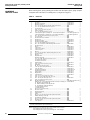
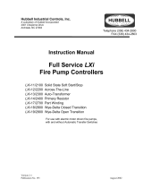
When ordering parts, specify quantity, part number and description of part, giving complete
nameplate data of the device. To identify parts, see Figure 6 on page 11.
Table 5: Parts List
Item Description Part Number Qty
1 Arc chute.................................................................................................51019-217-50 1
2 Blowout coil assembly.............................................................................51019-205-50 1
3 Blowout coil guard...................................................................................51019-237-01 1
4 1/4'' - 20 x 1/2'' pan head screw with captive lock washer......................
■
1
5 1/4'' - 20 x 7/8'' slotted hex head cap screw............................................
■
2
6 1/4'' lock washer......................................................................................
■
2
7 5/16'' - 18 x 1'' hex head cap screw........................................................
■
2
8 5/16'' lock washer....................................................................................
■
8
9 1/4'' - 20 x 3/8'' flat head brass screw.....................................................21203-20120 1
✝
10 Contact tip kit (copper) consisting of 2 - sets of tips and hardware........Class 9998, Type MG-1 or 1
Contact tip kit (silver) consisting of 2 - sets of tips and hardware...........Class 9998, Type MG-2 1
11 3/8'' - 16 x 7/8'' silicon bronze hex head cap screw................................
■
2
12 1/4'' -20 hex nut.......................................................................................
■
1
13 3/8'' silicon bronze lock washer...............................................................
■
3
14 Auxiliary arm...........................................................................................51019-255-50 1
15 Auxiliary arm spring................................................................................50502-602-33 1
16 Auxiliary arm spring retainer...................................................................51019-270-01 1
17 1/4'' - 20 x 3/8'' slotted hex head cap screw............................................
■
2
18 3/8'' - 16 x 2'' headless slotted half dog point set screw .........................21802-20480 1
19 3/8'' plain washer....................................................................................
■
4
21 Shunt ......................................................................................................51019-204-50 1
22 Contact arm............................................................................................51019-214-51 1
23 Contact arm support...............................................................................51019-229-50 1
24 Contact arm pin ......................................................................................51019-251-07 1
25 Bearing ...................................................................................................29005-32220 2
26 1/4'' - 20 x 3/4'' headless slotted half dog point set screw ......................21802-24320 1
27 Auxiliary arm pin.....................................................................................51019-251-05 1
28 Bearing ...................................................................................................29005-24161 2
29 Magnetic latch.........................................................................................51019-284-01 1
Magnetic latch plate................................................................................51019-285-01 1
1/4'' - 20 x 1 5/8'' bronze hex head cap screw........................................
■
1
1/4'' bronze plain washer........................................................................
■
1
1/4'' bronze lock washer..........................................................................
■
1
30 Armature plate........................................................................................51019-233-01 1
31 5/16'' - 18 x 3/4'' hex head cap screw.....................................................
■
2
32 Nameplate ..............................................................................................51139-242-01 1
33 #6 - 32 x 1/4'' pan head screw................................................................
■
2
34 Core cap spacer (phosphor bronze).......................................................50502-006-11 1
35 Core cap (steel)......................................................................................51019-292-01 1
✝
36 Operating coil 230/240V.........................................................................51019-243-53 or 1
Operating coil 115/120V.........................................................................51019-243-56 1
37 Spring washer.........................................................................................51019-041-01 1
38 Magnet frame..........................................................................................51019-248-50 1
39 Contactor base .......................................................................................51019-238-50 1
40 5/16'' - 18 x 2-1/2'' hex head cap screw..................................................
■
1
41 5/16'' - 18 x 3/4'' slotted hex head cap screw..........................................
■
2
42 3/8'' - 16 x 7/8'' hex head cap screw.......................................................21401-20240 1
43 5/16'' - 18 x 5/8'' hex head cap screw.....................................................
■
1
✝
46 Electrical interlock kit..............................................................................Class 9999, Type MX-11 or 1
Bulk pack of 5 - sets of replacement interlock contacts consisting of:....51075-038-54 1
10 - Movable contact tip (item 49)
10 - Bottom stationary contact tip (item 53)
10 - Top stationary contact tip (item 54)
4 - Spring retainer (item 50)
2 - Spring (item 51)
47 #10 - 24 x 1'' pan head screw.................................................................
■
2
48 #10 Lock washer.....................................................................................
■
2
49 Movable contact tip.................................................................................
■
2
50 Spring retainer........................................................................................
■
2
51 Spring .....................................................................................................
■
1
52 #10 - 24 x 1/2'' pan head screw with captive lock washer.......................
■
1
53 Bottom stationary contact tip ..................................................................
■
2
54 Top stationary contact tip........................................................................
■
2
55 #10 - 24 x 3/4'' pan head screw with captive lock washer.......................
■
1
56 #10 plain washer.....................................................................................
■
3
57 Core cap base ........................................................................................51019-311-01 1
■
Obtain standard hardware, listed without Square D part number, from a local hardware supplier.
✝
Parts recommended for general maintenance.
NOTE: The following user modification kits are also available for this contactor:
Class 9999 Type MK-2 pneumatic timer kit
Class 9999 Type ML-2 power lug kit consisting of 4 - clam shell lugs
ORDERING
INSTRUCTIONS

Bulletin No. 50006-369-10 Single-Pole DC Contactors, Normally Closed
February 1998 Exploded Assembly Drawing
11
©
1998 Square D All Rights Reserved
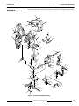
Figure 6 identifies items in the parts list and in the maintenance and adjustment procedures.
EXPLODED
ASSEMBLY DRAWING
Figure 6: Contactor Assembly Drawing
40
1
8
12
39
654
3
17
6
15
16
87
2
10
13
11 843
9
37
36
38
28 11
13
10
14
18
32
33
22
27
25
24
19 812
21
19
8
5648
47
46
5150 49
52
56
53
54
55
56
57
35
34
13
11
30
841
26 19 12
19
8
31
23
42

Electrical equipment should be serviced only by qualified electrical maintenance personnel, and this document should
not be viewed as sufficient instruction for those who are not otherwise qualified to operate, service or maintain the
equipment discussed. Although reasonable care has been taken to provide accurate and authoritative information in
this document, no responsibility is assumed by Square D for any consequences arising out of the use of this material.
Single-Pole DC Contactors, Normally Closed Bulletin No. 50006-369-10
Troubleshooting February 1998
© 1998 Square D All Rights Reserved
12
Square D and are registered trademarks of Square D Company.
Square D Company
8001 Hwy 64 East
Knightdale, NC 27545
(919) 266-3671
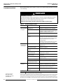
When troubleshooting, refer to Table 1 on page 1 for contactor ratings and Table 2 on page
1 for coil ratings.
Table 6: Troubleshooting Procedure
Problem Possible Causes Corrective Action
Contacts will not
open or operation
is sluggish.
Improper or inoperative
operating coil. Visually verify coil part number. Measure
resistance to determine if coil is inoperative.
Low control circuit voltage. Measure control circuit voltage. It must be at
least 80% of rated coil voltage. If it is zero, the
problem is elsewhere in the circuit.
*
Loose connection in control
circuit. Inspect connections and tighten if loose.
Mechanical interference or
binding. Inspect for mechanical interference or binding:
- Manually close the armature plate and check
the cap screw head on the core of the magnet
frame assembly clears the hole in the
armature plate.
- Manually close the armature plate, check that
the auxiliary arm bearings are not binding.
Contact tips
overheat, short
contact tip life.
Loose connections. Inspect contact tips and shunt connections and
tighten if loose.
Movable or stationary contact
tip not properly aligned. Align contact tips according to “Contact Tip
Alignment” on page 4.
Foreign matter on contact
surfaces. Remove foreign matter.
Contact tips worn beyond
recommended limits. Replace contact tips according to "Contact Tip
Replacement" on page 6.
Contact surfaces severely
scored or burned. Inspect contact surfaces and dress with a file,
as required.
Arc chute not properly installed. Visually verify that arc chute is pivoted to the
fully down position.
Inoperative closing spring. Replace the spring.
Normal load currents below 5%
of rated contactor current. Use smaller size contactor.
*
Operating coil
overheats. Improper or inoperative coil. Visually verify coil part number. Measure
resistance to determine if coil is inoperative.
High voltage condition on coil. Measure control circuit voltage. It must not
exceed 110% of rated coil voltage.
*
Loose connection at coil
terminals. Check connection and tighten if loose.
*See danger statement above.
TROUBLESHOOTING
HAZARDOUS VOLTAGE
Troubleshooting procedures marked with an asterisk (*) require application of power.
Do not touch contactor with power applied. Disconnect power to contactor before
performing any other troubleshooting corrective action.
Failure to observe this precaution will result in death or serious injury.
DANGER
!
-
 1
1
-
 2
2
-
 3
3
-
 4
4
-
 5
5
-
 6
6
-
 7
7
-
 8
8
-
 9
9
-
 10
10
-
 11
11
-
 12
12


Electric Controller & Mfg. (EC&M) DC Magnetic Contactor - Class 7004 Type MGO3, 300A, SPNC, Size NEMA5, Series A Installation guide
- Type
- Installation guide
Ask a question and I''ll find the answer in the document
Finding information in a document is now easier with AI
Related papers
-
 Electric Controller & Mfg. (EC&M) DC Magnetic Contactor - Class 7004 Type MGO1 MGAO1, 300A 400A, SPNO, Size NEMA5 5A, Series A Installation guide
-
 Electric Controller & Mfg. (EC&M) DC Magnetic Contactor - Class 7004 Type MGAO3, 400A, SPNC, Size 5a, Series A Installation guide
-
 Electric Controller & Mfg. (EC&M) 7004-61 ECM Size 1 and 2 NO Contactor Installation guide
-
 Electric Controller & Mfg. (EC&M) Magnet Controller - Class 6815 Type M35, M60, MF35, MF60, 15-35 25-60A Installation guide
-
 Electric Controller & Mfg. (EC&M) DC Installation guide


Other documents
-
Lincoln Electric SAF-600 Operating instructions
-
Eaton 36-inch wide vacuum-break starters rated 360 amperes, 7200 volts, slide-out type Operating instructions
-
Allen-Bradley CENTERLINE 2100 Installation Instructions Manual
-
Hobart TM416 Operation And Maintenance Instruction Manual
-
ESAB DIP/STICK® 160 Power Source/Wire Feeder/Gun User manual
-
Lincoln Electric MECH. Travel Power Pack Operating instructions
-
Miller TRAILBLAZER 55G Owner's manual
-
 Rockwell Automation Allen-Bradley 7712 User manual
-
 Metron/Metron-Eledyne LXI Installation guide
-

