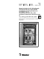
Electric Controller & Mfg. (EC&M) Magnet Controller - Class 6815 Type M35, M60, MF35, MF60, 15-35 25-60A Installation guide
- Type
- Installation guide

6815-14
11/00
Columbia, SC, USA
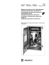
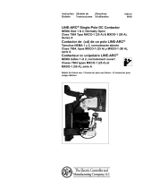
Magnet Controllers for DC Lifting Magnets
Class 6815 Type M35, MF, 35, M60, and MF60
Controladores de imán para imanes de
levantamiento de cd
Clase 6815 tipos M35, MF35, M60, y MF60
Contrôleurs d’aimant pour aimants de levage
cc
Classe 6815 types M35, MF35, M60, et MF60
Instruction Boletín de Directives
Bulletin instrucciones d'utilisation
Retain for future use. / Conservar para uso futuro. / À conserver pour
usage ultérieur.


Bulletin No. 6815-14 Magnet Controllers for DC Lifting Magnets
11/00 Class 6815 Type M35, M60, MF35, & MF60
3
© 1982–2000 Schneider Electric All Rights Reserved
ENGLISH
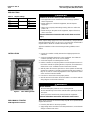
These ampere ratings apply to the cold current drawn by a magnet when its
internal temperature is 68–77 °F (20–25 °C). Do not use the controller with a
magnet above or below the controller rated ampere range.
Type MF controllers include a slow-discharge fanning (dribble) control
feature.
1. Unpack the controller carefully. Remove the shipping tape from the
contactors.
2. Check the nameplate data for the correct equipment. Check that the
contactor operating coils are the correct voltages.
3. Check that all parts are undamaged and secure.
4. Bolt the controller securely into position. Provide adequate clearance in
front of the controller for opening the door, inspection, and maintenance.
Allow at least 1.5 in. ventilation clearance below the controller.
5. With all power disconnected, pivot the arc chutes upward and manually
operate the contactors. The power contact tips should meet squarely. If
they do not, refer to “Contact Tip Alignment” in the “Adjustment” section
of the contactor instruction bulletin.
6. Pivot the arc chutes back to their proper position.
7. Wire all external circuits to the disconnect switch in accordance with the
wiring diagram on the inside of the door.
NOTE: Drop contactors 1D and 2D and drop relay DR do not operate with the
magnet disconnected.
1. Place the pilot device in the “Drop” position.
2. Apply voltage to the controller. For the best performance, ensure that the
voltage is between 230–250 V.
HAZARD OF ELECTRIC SHOCK, BURN, OR EXPLOSION
• This equipment must be installed and serviced only by qualified
electrical personnel.
• Before working on or inside the equipment, turn off all power
supplying it.
• Always use a properly rated voltage sensing device to confirm the
power is off.
• Before turning on the power to this equipment, replace all devices,
doors, and covers.
Failure to follow these instructions will result in death or serious
injury.
DANGER
INTRODUCTION
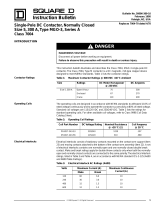
Table 1: Ampere Ratings
Type Series Rating (A)
M35 A15–35
M60 25–60
MF35 A and B 15–35
MF60 25–60
Figure 1: Class 6815 Type M60
INSTALLATION
ARCING HAZARD
• Electrical interruption produces an arc and hot particles.
• Do not stand directly in front of the controller when operating it with the
door open.
• Service personnel should wear personal protective equipment.
Failure to follow these instructions will result in serious burns.
DANGER
PRELIMINARY STARTUP
With Magnet Disconnected

Magnet Controllers for DC Lifting Magnets Bulletin No. 6815-14
Class 6815 Type M35, M60, MF35, & MF60 11/00
© 1982–2000 Schneider Electric All Rights Reserved
4
ENGLISH
3. Check the polarity with a voltmeter.
NOTE: The controller does not operate if the polarity is reversed.
4. With voltage applied to the controller, place the pilot device in “Lift“
position. Lift contactors 1L and 2L (also fanning contactor F in Type MF
controllers) should close freely.
5. On Type MF controllers only, hold the FAN push button down. Lift
contactors should open. Release the FAN push button. Lift contactors
should re-close.
6. De-energize the controller by placing the pilot device in the drop position.
The contactors in step 4 should re-open.
1. Disconnect power from the controller.
2. Make certain that all the arc chutes are pivoted to their fully down
position.
3. Connect the magnet.
4. Apply power to the controller.
5. Repeat steps 4–6 as listed in “Preliminary Startup”. Note that when drop
is initiated, drop contactors DR, 1D, and 2D should close for
approximately 1–3 seconds.
To adjust the controller for a clean drop without repicking, the controller has
a reverse current rheostat and monitor light. To obtain the best setting for a
given magnet, start with the rheostat knob set near MIN, then make lifts and
drops at successively higher settings until the light blinks at the end of the
drop cycle (see Monitor Light Operation nameplate), or until a clean drop is
obtained. Do not set the knob higher than necessary to get a clean drop on
all types of loads being handled. Reset the rheostat when the magnet is
changed.
Inspect contact tips on the lift and drop contactors on a regular basis for wear
and excessive pitting (see “Maintenance” in the contactor instruction bulletin
for instructions). Square D recommends that replacement contact tip kits be
kept on hand. Each kit contains two contact tips and mounting hardware.
Replace
both tips together.
During operation, periodically inspect for abnormal conditions. In particular,
inspect for the following conditions while the device drops a load:
STARTUP
With Magnet Connected
ADJUSTMENT FOR CLEAN DROP
PREVENTIVE MAINTENANCE AND
TROUBLESHOOTING
HAZARDOUS VOLTAGE
This equipment must be installed and serviced only by qualified
electrical personnel.
Failure to follow this instruction will result in death or serious
injury.
ARCING HAZARD
• Electrical interruption produces an arc and hot particles.
• Do not stand directly in front of the controller when operating it with
the door open.
• Service personnel should wear personal protective equipment.
Failure to follow these instructions will result in serious burns.
DANGER

Bulletin No. 6815-14 Magnet Controllers for DC Lifting Magnets
11/00 Class 6815 Type M35, M60, MF35, & MF60
5
© 1982–2000 Schneider Electric All Rights Reserved
ENGLISH
• Excessive or unequal arcing when the two lift contactors open.
• Excessive or unequal arcing when the two drop contactors open.
Should either condition occur, shut down the system to prevent further
damage, and check the following items:
• Contact tips and pigtail connectors on all contactors
• Electrical continuity of all fuses, resistors, and the reverse current rheostat
• Electrical continuity of all electrical interlocks
• Shorts and grounds in the system, including the generator, cable, reel,
and magnet. Because ohmmeters may not detect grounds, use a 500 V or
1000 V meg-ohmmeter.

Magnet Controllers for DC Lifting Magnets Bulletin No. 6815-14
Class 6815 Type M35, M60, MF35, & MF60 11/00
© 1982–2000 Schneider Electric All Rights Reserved
6
ENGLISH
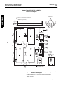
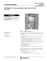
Figure 2: Standard Type M-35, MF-35, M-60, MF-60 Magnet Controllers
Parts Location Diagram
NOTE: For definitions of callouts and resistor values refer to
Table 2 on page 7.
Side View Of
Resistors
(Front)
(Rear)
4
5B 5A
3
F
15B
15A
15A
15B
2SP
2 Res
15 1 Rec
ISP
19
20
17
18
16
13
12
7
14A 14B
10
8
9
6
8
6B
8
M2
2L 1D
M1
-
6B 1L 2D
6
9
7
+
4
5B
5A
Denotes Components Furnished Only
On Type MF-35 & MF-60 Controllers
(With Fanning Feature)
I Res (Four Resistors)
F Res (Two Resistors)
DR
ITB
ILM
Main
I.D. N.P.
IFU
2FU
3FU
4FU
21
On Series B Only
Reverse
Current
Adjust
Standard Type M-35, MF-35, M-60, MF-60
Parts Location Diagram

Bulletin No. 6815-14 Magnet Controllers for DC Lifting Magnets
11/00 Class 6815 Type M35, M60, MF35, & MF60
7
© 1982–2000 Schneider Electric All Rights Reserved
ENGLISH
NOTE: In Table 2 the quantity in parentheses is for the optional fanning
feature.
Table 2: Type M35, M60, MF35, and MF60 Magnet Controller Parts
Symbol Item
No. Description [1] Qty. Part No. or Class and Type No.
Type M35 Type M60 Type MF35 Type MF60
—
1A Assembled control panel
(Does not include items 2, 4, 5A, or 5B) 1Class 6815
Type MP35 [2] Class 6815
Type MP60 [2] Class 6815
Type MFP35 [2] Class 6815
Type MFP60 [2]
2 Enclosure only, with door 1 50911-048-51
2A Door only 1 50911-064-52
F3 Fanning relay (1) (none) Class 8501 Type GDO31 with
240 V DC coil [3]
3A Replacement contact tip set for item 3 (1) — Class 9998 Type GG4 Kit
FRES 4 Fanning resistors (located above items 5A and 5B) (2) (none) 26114-52330, 3 Ω 420 W
1RES 5A Discharge resistors, center tapped
(located behind item 5B) 326114-52410
10 Ω 420 W 26114-52355
5.5 Ω 420 W 26114-52410
10 Ω 420 W 26114-52355
5.5 Ω 420 W
5B Discharge resistor (located in front of item 5A) 1 26114-52337
3.75 Ω 420 W 26114-52320
2 Ω 420 W 26114-52337
3.75 Ω 420 W 26114-52320
2 Ω 420 W
1L, 2L 6Lift contactors, complete except for lugs (6B) and
electrical and mechanical interlock equipment (items 8
and 9) 2 Class 7004 Type MXDO1, Form Y781 with 120 V coil [4]
6A Replacement silver-faced contact tips for two lift
contactors 1Class 9998 type MX2
Do not substitute.
(contains 2 moveable tips, 2 stationary tips, and hardware)
1L, 2L 6B Power terminal lugs 4 25050-03610
1D, 2D 7Drop Contactors, complete except for electrical and
mechanical interlock equipment (items 8 and 9) 2 Class 7004 Type MXCO1 with 120 V coil [5]
7A Replacement contact tips for two drop contactors 2 Class 9998 Type MX1 kit
(contains 2 moveable tips, 2 stationary tips, and hardware)
1L, 2L, 1D, F 8 Electrical interlocks (for items 6 and 7)
(quantity shown for standard controllers)
Class 9999 Type MX11 kit
(each kit contains 1 N.O. & 1 N.C. interlock)
One kit required for each 2L, 1D, and 2D. Two kits required for 1L.
1L-2D, 1D-2L 9A Mechanical interlocks 2 Class 9999 Type MM1 kit [5]
DR 10 Drop relay 1 Class 7001 Type DO22S5 with 48 V DC coil
2RES 11 25 W/50 Ω Reset resistor 1 26160-26450
3RES 12 2 W/82 Ω Control resistor 1 26108-08220
4RES 13 5 W/1.2 kΩ Control resistor 1 26101-13612
1RH 14A 50 W/1.0 kΩ Rheostat
(reverse current adjustment) 1 26198-34310
14B Pointer knob (for item 14A) 1 29203-04002
1REC, 2REC,
1SP, 2SP 15 Heat sink assembly, complete (includes 2 item 15A
diodes, 2 item 15B surge suppressors, 2 heat sink plates,
and 2 mounting brackets) 1 50911-010-54
1REC, 2REC 15A Diodes (power circuit) 2 27906-33850
1SP, 2SP 15B Surge suppressors 2 27920-93200
3REC 16 Diode (control circuit) 1 27906-11602
1FU, 2FU 17 Fuses (power circuit) 2 25413-00260 (Bussman FRN7.0 or equal)
3FU, 4FU 18 Fuses (control circuit) 2 25419-10091 (Bussman KTK3 or equal)
1TB 19 Control terminals (quantity shown for standard M and MF
controllers) 9 Class 9080 Type GP3
1LM 20 Monitor light module 1 50910-017-51
4REC 21 Diode assembly (on Type MF Series B only) (1) 50910-030-50
[1] Indented items listed directly under a device are component parts of that device.
[2] Add Form number (if any) from main nameplate on original Type M panel.
[3] See bulletin 311AS for relay components.
[4] See bulletin 7004-63 for contactor components.
[5] See bulletin 7004-61 for contactor components and instructions.

Magnet Controllers for DC Lifting Magnets Bulletin No. 6815-14
Class 6815 Type M35, M60, MF35, & MF60 11/00
© 1982–2000 Schneider Electric All Rights Reserved
8
ENGLISH
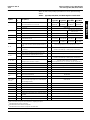
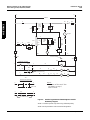
Figure 3: Standard Type M35 and M60 Magnet Controller Elementary
Diagram
NOTE: Controller operates only when using indicated polarity.
NOTE: Text in parentheses refer to terminal designations.
(-)
230VDC
M1 2D 62FU
Magnet
2L
ILM
5
IL
7
2 Res
25 Ω
50 W
1 Rec
ISP
5
4
(+)
IL
1 FU 11D 22 Rec
2 SP
3
I Res
See
Note
A
DR
3FU
3 Rec
9
P
Pushbutton Operation
Lift
Drop
Fan S
T
13 ID 12 2D 11 IL
ID 2D
DR
M2
22
3 Res
82 Ω
2W
4 Res
1.2k Ω
5W
1 RH
1k Ω
50W
21
M2
4 FU
20
2L
10
19
18
2L
17
1L
15
DR
16
14
Master Switch Operation
Lift
Drop
-- OR --
*
*
PS
(Not Used)
Note A:
R
To
(-)
1L
R
For values of I Res see Table 2
on page 7, items 5A & 5B.

Bulletin No. 6815-14 Magnet Controllers for DC Lifting Magnets
11/00 Class 6815 Type M35, M60, MF35, & MF60
9
© 1982–2000 Schneider Electric All Rights Reserved
ENGLISH
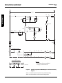
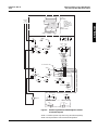
Figure 4: Standard Type M35 and M60 Magnet Controller Connection
Diagram
NOTE: Controller operates only when using indicated polarity.
NOTE: Text in parentheses refer to terminal designations.
M2
-
-
10
M22L20
M1
+
(+)
11
M12L10
(-) (+)
230 Vdc
Line 5
(Rear)
(Front)
54
3
(For Resistor Values
see Table 2 on page 7
items 5A & 5B.)
I Res
2 Rec 1 Rec
3M1
(2) (2)
ISP
2SP
2(1) (1) 5
R
ILM
BK
+
-
+
-
1
6
9
20
1FU
2FU
3FU
4FU
9
P
F
S
T
4
22
21
13
24
3 Rec
4 Res
3 Res
19ID
2
13 12 M2 22DR
16 15 421 1RH
21 4
(Front view)
1
18
17 18
Magnet
Pushbutton Station
-- or --
Master Switch
Lift
Drop
T
P
R
S
DLS
P
75
13
15 14
17 11 12
M1
19 20
2D
2 Res
76
M1
M2
R

Magnet Controllers for DC Lifting Magnets Bulletin No. 6815-14
Class 6815 Type M35, M60, MF35, & MF60 11/00
© 1982–2000 Schneider Electric All Rights Reserved
10
ENGLISH
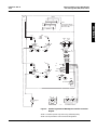
Figure 5: Standard Type MF35 and MF60 Magnet Controller
Elementary Diagram
NOTE: Controller operates only when using indicated polarity.
NOTE: Text in parentheses refer to terminal designations.
(-)
230VDC
M1 2D 62FU
Magnet
F Res
See
Note
A
8
LL
2L
ILM
5
IL
7
2 Res
25 Ω
50 W
1 Rec
ISP
5
4
(+)
IL
1 FU 11D 22 Rec
2 SP
3
I Res
See
Note
A
DR
3FU
3 Rec
9
P
Pushbutton Operation
Lift Drop
Fan
S
F13
23
ID 12 2D
BK
11
F
IL
ID 2D
DR
M2
22
3 Res
82 Ω
2W
4 Res
1.2k Ω
5W
1 RH
1k Ω
50W
21
M2
4 FU
20
R
2L
10
4Rec
On Series B Only
19
18
2L
17
1L
15
DR
16
F
F
T
24
On Series B Only
Master Switch Operation
Lift
Drop
-- OR --
Fan
**
PS
T
P
F
S
(Not Used)
On Series B Only
Note A:
For values of I Res and F Res
see Table 2 on page 7,
items 5A & 5B.

Bulletin No. 6815-14 Magnet Controllers for DC Lifting Magnets
11/00 Class 6815 Type M35, M60, MF35, & MF60
11
© 1982–2000 Schneider Electric All Rights Reserved
ENGLISH
Figure 6: Standard Type MF35 and MF60 Magnet Controller
Connection Diagram
NOTE: Controller operates only when using the indicated polarity.
NOTE: Text in parentheses refer to terminal designations.
M2
-
-
10
M22L20
M1
+
(+)
11
M12L10
(-) (+)
230 Vdc
Line
8
5(Rear)
(Front)
5
4
M2 3
F Res
(Top Row)
NOTE:
For values of
F Res & I Res
see Table 2 on
page 3, items 4,
5A & 5B.
I Res
(Bottom Row)
M2 M2 23 PP
8820 24 16
2 Rec 1 Rec
3M1
(2) (2)
ISP
2SP
2(1) (1) 5
R
ILM
BK
F
+
-
+
-
1
6
9
20
1FU
2FU
3FU
4FU
9
P
F
S
T
4
22
20
21
13
24
BK 3 Rec
23
4 Res
3 Res
R
4Rec
19ID
2
13 12
M2 22DR
16 15 421 1RH
21 4
(Front view)
1
18
17 18
On Series B Only
Magnet
On Series B Only
Pushbutton Station -- or -- Master Switch
Lift Drop
PTS
Fan
TF
ST
PF
S
Fan
DL
SP
75
13
15 14
17 11 12
M1
19 20
2D
2 Res
76
M1
-
 1
1
-
 2
2
-
 3
3
-
 4
4
-
 5
5
-
 6
6
-
 7
7
-
 8
8
-
 9
9
-
 10
10
-
 11
11


Electric Controller & Mfg. (EC&M) Magnet Controller - Class 6815 Type M35, M60, MF35, MF60, 15-35 25-60A Installation guide
- Type
- Installation guide
Ask a question and I''ll find the answer in the document
Finding information in a document is now easier with AI
Related papers
-
 Electric Controller & Mfg. (EC&M) Magnet Controller - Class 6815 Type M135, M175, MF135, MF175, 60-135A 85-175A Installation guide
-
 Electric Controller & Mfg. (EC&M) DC Magnetic Contactor - Class 7004 Type MGO1 MGAO1, 300A 400A, SPNO, Size NEMA5 5A, Series A Installation guide
-
 Electric Controller & Mfg. (EC&M) 7004-61 ECM Size 1 and 2 NO Contactor Installation guide
-
 Electric Controller & Mfg. (EC&M) DC Magnetic Contactor - Class 7004 Type MGAO3, 400A, SPNC, Size 5a, Series A Installation guide
-
 Electric Controller & Mfg. (EC&M) DC Magnetic Contactor - Class 7004 Type MGO3, 300A, SPNC, Size NEMA5, Series A Installation guide
-
 Electric Controller & Mfg. (EC&M) DC Crane Control - Class 6121 Installation guide


Other documents
-
3M D131159 Operating instructions
-
 YORKVILLE AP800 User manual
-
Manhattan Power Adapter 90W Specification
-
Yorkville Sound YS4040 User manual
-
-
IC Intracom 307895 User manual
-
Planar MP60 User manual
-
 YORKVILLE AP2020 User manual
-
 YORKVILLE V22 User manual
-
 YORKVILLE AP4040 - SERVICE User manual


