Page is loading ...

Version 2.1
Publication No. 193 August 2002
Hubbell Industrial Controls, Inc.
A subsidiary of Hubbell Incorporated
4301 Cheyenne Drive
Archdale, NC 27263
Telephone (336) 434-2800
FAX (336) 434-2803
Instruction Manual
Full Service LXi
Fire Pump Controllers
LXi-11/2100 Solid State Soft Start/Stop
LXi-12/2200 Across-The-Line
LXi-13/2300 Auto-Transformer
LXi-14/2400 Primary Resistor
LXi-17/2700 Part Winding
LXi-18/2800 Wye-Delta Closed Transition
LXi-19/2900 Wye-Delta Open Transition
For use with electric motor driven fire pumps,
with and without Automatic Transfer Switches
HUBBELL

Full Service Fire Pump Controllers
Version 2.1
Publication No. 193 Page 1 of 34 August 2002
Introduction .................................................................................................................................................... 3
Specifications and Certifications .................................................................................................................... 4
Specifications ............................................................................................................................................. 4
Certifications .............................................................................................................................................. 4
Receiving, Handling, and Storage .................................................................................................................. 5
Installation...................................................................................................................................................... 5
Controller Operation....................................................................................................................................... 6
LXi Series Controller User Interface .............................................................................................................. 6
Display Indications..................................................................................................................................... 7
LCD Panel .............................................................................................................................................. 7
LED Panel .............................................................................................................................................. 7
User Input................................................................................................................................................... 9
Keypad Buttons ...................................................................................................................................... 9
Normal Buttons .................................................................................................................................. 9
Special Function Buttons.................................................................................................................. 10
Password Protection ............................................................................................................................. 10
Navigating the System Menus.................................................................................................................. 11
Set Time hh:mm:ss: Sets the system Real Time Clock for display and logging .................................. 11
Timer Config Menu:............................................................................................................................. 11
System Config Menu:........................................................................................................................... 11
Remote Inputs........................................................................................................................................... 12
Programming and Calibration Procedure ..................................................................................................... 12
Programming operational Setpoints ......................................................................................................... 13
Timers................................................................................................................................................... 13
Minimum Run Period Timer ............................................................................................................ 13
Start Accelleration Timer ................................................................................................................. 13
Start Delay Timer ............................................................................................................................ 13
Start and Stop Pressure......................................................................................................................... 14
Start pressure .................................................................................................................................... 14
Stop Pressure .................................................................................................................................... 14
Auto Pressure Stop Enable ............................................................................................................... 14
Full Load Current ................................................................................................................................. 14
Time And Date Setup ........................................................................................................................... 15
Time.................................................................................................................................................. 15
Date .................................................................................................................................................. 15
Communications Paramaters ................................................................................................................ 15
Restoring the System Configuration..................................................................................................... 15
System Calibration ................................................................................................................................... 16
Calibrating Line Voltages, currents, and Pressure................................................................................ 16
Automatic and Manual Starting Methods..................................................................................................... 16
Manual Start of the Controller.............................................................................................................. 16
Local Manual Start ........................................................................................................................... 17
Remote Start ..................................................................................................................................... 17
Emergency Manual Start .................................................................................................................. 17
Automatic start and Automatic Stop Functions....................................................................................17
System Timers.......................................................................................................................................... 18
Types of Starting Systems ........................................................................................................................ 18
LXi-11/2100 Solid State Soft Start/Stop ............................................................................................... 19
S2MC Adjustments ............................................................................................................................... 20
Indications ............................................................................................................................................ 20
LXi-2/2200 Across-the-Line ................................................................................................................. 21
LXi-13/2300 Auto-Transformer............................................................................................................ 22
LXi-14/2400 Primary Resistor .............................................................................................................. 22

Full Service Fire Pump Controllers
Version 2.1
Publication No. 193 Page 2 of 34 August 2002
LXi-17/2700 Part Winding.................................................................................................................... 23
LXi-18/2800 Wye-Delta Closed Transition .......................................................................................... 23
LXi-19/2900 Wye-Delta Open Transition ............................................................................................ 24
Startup Procedure ......................................................................................................................................... 24
Preventive Maintenance ........................................................................................................................... 27
Troubleshooting........................................................................................................................................ 27
Coil and Contact Replacement ................................................................................................................. 28
Current Shunt Trip Module .......................................................................................................................... 29
General ..................................................................................................................................................... 29
Application Information ........................................................................................................................... 30
Troubleshooting........................................................................................................................................ 30
Full Service Fire Pump Controller Parts....................................................................................................... 31
Notes
Refer to job drawings for options.
For combination Automatic Transfer Switch/Fire Pump Controller applications, refer to Publication No.
201 for the LX-450 Transfer Switch.

Full Service Fire Pump Controllers
Version 2.1
Publication No. 193 Page 3 of 34 August 2002
Introduction
The Hubbell Full Service Fire Pump Controllers provide automatic and manual control of
an electric motor driven fire pump.
All Controller components are inside the cabinet with indicating displays, control panels,
and switch handles located next to the door. A pressure transducer initiates automatic
starting of the pump motor. The Controller monitors the power phases, current, and
voltage. The ISOLATING SWITCH has a door interlock feature to prevent the door
from being opened when the switch is closed. The Controller also has a EMERGENCY
MANUAL CONTROL handle to start the fire pump manually.
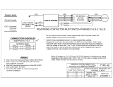
Figure 1 Block diagram of Across-The-Line type Controller showing one phase
The System Control Panel and Micro Control Unit are responsible for performing most of
the system functions, including monitoring the System Power Quality, Automatic Start
Functions, and System Timer operations. The Control Panel is powered by a self
contained power supply that is fed from the control transformer. The Metering
transformer is used to convert the Line voltages to levels appropriate for analysis by the
Micro Controller.
The LCD Display panel consists of a 4 x 20 character text display that continuously
displays the system pressure, three phase voltages, three phase line currents, and time.
The LCD panel also contains a numeric keypad for user entry and programming of the
user setable functions.
The LED display panel provides real time information regarding the status of the system
including power availability, presence of alarm conditions, and indication of any active
timers.

Full Service Fire Pump Controllers
Version 2.1
Publication No. 193 Page 4 of 34 August 2002
Specifications and Certifications
Specifications
Micro Controller System Hitachi H8 – 2144F
A/D Converter 7 Channels of 10 Bit A/D
Power Supply +5V, +/- 12V
LED Indications 20 LEDS (16 on LED panel 4 on LCD Panel)
Inputs Buttons Numeric Keypad + various special Functions
Initialization Delay 2 Second Delay for Displaying System Info
Power Quality Specifications
Voltage (two ranges 240 and 480)
240V Range - 200, 208, 220, 230, 240
480V Range - 380, 415, 440, 460, 480 VAC
Phase Loss/Reversal Detection A-B-C phase rotation
Maximum Voltage 10% of highest nominal voltage
Maximum Frequency Shift 0.1 Hz
Phase Loss / Failure Excess of +/- 15% nominal voltage in one phase
Shunt Trip Current Monitor Output 22–28 VDC at 2.5 A max.
+12 VDC
Indication blue LED, Power, motor current present
red LED, Overload motor current more than three
times FLC
Surge Arrestor 650 V rating
Temperature Operating: −4° F to 104° F (−20° C to 40° C)
Storage: −4° F to 182° F (−20° C to 85° C)
Certifications
All Hubbell Full Service Fire Pump Controllers are built to NFPA 20 requirements. The
Controllers are listed by:
Underwriters Laboratory Factory Mutual
New York City-MEA Dept. of Buildings

Full Service Fire Pump Controllers
Version 2.1
Publication No. 193 Page 5 of 34 August 2002
Receiving, Handling, and Storage
1. Immediately upon receipt, carefully unpack and inspect the Controller for damage
that may have occurred in shipment. If damage or rough handling is evident, file a
damage claim with the transportation carrier.
2. If the Controller must be stored, cover it and then place it in a clean, dry location.
Avoid unheated locations where condensation can result in damage to the insulation
or corrosion of metal parts.
Installation
1. Consult the motor nameplate to determine voltage, current, and horsepower rating
and compare with the Controller nameplate for matching data. Also, ensure that the
Controller is correct for the motor, wye-delta, part winding, etc.
2. Release the door interlock by moving the ISOLATING SWITCH to the OFF
position. The door interlock can also be released by using a screwdriver to turn the
interlock defeat on the side of the operating handle.
3. Inspect the control transformer’s primary connections for agreement with the line
voltage of the incoming power.
4. Inspect the metering transformers high side voltage rating for agreement with the line
voltage of the incoming power.
5. Check panel wiring and component mountings for loose fasteners resulting from
vibration during shipping.
6. Check all power wire and power component connections (bus bars and cables to
circuit breakers) for loose fasteners resulting from vibration during shipping.
7. Exercise all switches and contactors, without power, to see that they operate freely.
8. Choose a location or base for the Controller that is non-combustible and within site of
the motor. The base should not be subject to excessive vibration The Controller
should be level.
Caution: Before drilling and punching holes in the cabinet for wiring
connections, cover the components inside the cabinet with a
protective covering. Debris may cause shorts or prevent
operation of components.
9. Punch holes in the top or the bottom of the cabinet for conduit.
7. Connect the water pressure sensing line to the Pressure Transducer (1/4 NPT internal,
3/4-16 external, brass) fitting, bottom left, of the cabinet. For further details, consult
the latest edition of NFPA 20.
8. Connect the power supply conductors to the line side of the ISOLATING SWITCH
in the correct A-B-C phase sequence.
9. Connect the motor conductors to the load side of the motor contactor(s).

Full Service Fire Pump Controllers
Version 2.1
Publication No. 193 Page 6 of 34 August 2002
Note
Refer to the Controller field connection diagrams. Per the requirements of NFPA 20,
conductors are sized for no less than 125% of the motor FLC (full load current) and not
more than the lug sizes provided, as shown on the Controller field connection diagrams.
Refer to the NFPA 70 (NEC) for cable ratings. Secure conductors inside the cabinet so
they do not interfere or rub against the components
10. Connect the remote alarm contacts. Refer to the supplied Controller field connection
diagram for terminal points.
Controller Operation
Closing the ISOLATING SWITCH and CIRCUIT BREAKER-DISCONNECTING
MEANS energizes the Control and Metering transformers which in turn energizes the
system Controller. Upon System Initialization, the LCD displays a hello message for two
seconds.
At this point, the system is enabled and the Power Available LED (on the LED panel)
should be green and the phase reversal LED should be dark. If a phase failure is present
(i.e. a missing phase), the Power Available light will be red and the PFR relay contacts
will de-energize. If there is a phase reversal, this will be indicated by a red Phase
Reversal LED and the PRR relay contacts will provide remote indication of phase
reversal by de-energizing. The presence of either a phase failure or a phase reversal
condition will also cause the common alarm relay to de-energize.
The LXi series Fire Pump Controller is a microprocessor based system. The Controller
continuously monitors the “real time” line voltages, currents, and pressure. This
information is displayed on the LCD display by default. The Controller is also
responsible for the starting and stopping sequences (both manual and automatic with the
exception of the Emergency Manual Start).
The Controller contains a programming menu system which may be accessed by
pressing the “ESC/DEL” key. Upon pressing this key, the display will prompt for the
access code to keep unauthorized users from changing the system operation parameters.
The access code is a four digit number (between 0000 and 9999). If the ESC key is
pressed a second time (at the prompt), the system will return to normal operation and
restore the default display. Similarly, if no entry is made within ten seconds, the system
will also return to normal. After the correct password is entered, the system will display
one of the menu options. The menus are navigated with the up and down scroll buttons.
Once the desired menu option is displayed pressing the ENTER key will activate the
selection. At any time pressing ESC will back the display up to the previous level (or
exit the menu system).
LXi Series Controller User Interface
The User Interface to the LXi Series controller consists of two panels. The top panel
contains an 20 x 4 character alpha-numeric LCD display, a numeric keypad, special
function buttons, and four status indicator LEDs. The bottom panel consists of sixteen

Full Service Fire Pump Controllers
Version 2.1
Publication No. 193 Page 7 of 34 August 2002
LEDs arrayed in two columns. These LEDs are labeled with the corresponding meaning
and are used to convey status information about system status, alarms, pump operation,
and power quality. Not all LEDs are used in all applications, therefore the some labels
may be blank.
Display Indicators
The display system of the LXi Series Fire Pump Controller is broken into two major
subsections, the LCD panel and the LED panel. The details of the output indicators on the
two panels including the meaning of the LEDS is provided in the sections below.
LCD Panel
One of the primary functions of the LCD panel is to provide real time status information
regarding the system voltage, motor currents, and pressure. This information is displayed
on the default screen. Additional screens which display various other system operating
parameters are accessed by using the up and down scroll buttons. The scroll buttons are
indicated by the directional arrows on the numeric keypad (buttons 8,2 for up/down and
4,6 for left/right). Scrolling either up or down will cause the display to change to the next
alternate screen. The system will return to the default screen after a ten second delay if
no additional buttons are pressed.
In addition to the LCD, the panel also provides four LED indicators. The indicators and
their functions are presented here:
Local Manual Start: This (yellow) LED indicates that the system has started the pump
because the local manual start button was pressed.
Remote Start: This (yellow) LED indicates that the Controller has detected and started
due to a closure of the Remote Start Contacts.
Emergency Manual Start: This (red) LED indicates that the system was started by the
emergency manual start lever. While the system will stop, if the emergency manual start
is disengaged, the light will remain lit to indicate the abnormal condition.
Local Manual Stop: This (yellow) LED will remain lit for two seconds following a
local stop command (pressing the red Stop button). After the system has returned to idle,
this light will go out.
LED Panel
The LED panel consists of 16 LEDs that show various system status indications. A list
of the common indicators is presented here:
Power Available / Phase Failure: This LED is green when the Controller senses that all
three phases are available and within specification. In the case of a phase failure
condition, this LED turns red. The method of determining a phase failure depends on the
state of the system. If the system is idle, a phase failure is detected by an abnormal line
voltage(s) whereas if the pump is running, due to the potential of back EMF from the
motor, a phase failure is detected by an excessive current imbalance.

Full Service Fire Pump Controllers
Version 2.1
Publication No. 193 Page 8 of 34 August 2002
Pressure Switch Start: This LED is used to indicate that the system started due to the
pressure falling outside of the allowable window as determined by the Start Pressure and
Stop Pressure set points (see section on system programming). The LED turns yellow
when a pressure start sequence has been initiated and is unlit otherwise. The light goes
out, when the system returns to idle.
Accelleration Timer Active: When the system is performing a reduced voltage start, this
LED blinks green while the Start Acceleration timer is active. Once the timer has
expired, this light goes dark. Note: This item only applies to system with reduced
voltage starting capability.
Run Timer Active: When the system starts by automatic (pressure start), this LED
blinks green while the minimum run timer (set to ten minutes by default) is active. Once
the timer has expired, the led will go out.
Lockout On: The lockout indicator turns yellow, when the external lockout signal is
active. During a lockout condition, the system will not start. Since the lockout input is
multiplexed with the input for a low suction condition, if the lockout input is asserted
while the pump is running, the condition will be interpreted as a low suction condition,
which will halt the pump. Note: This feature is not allowed per NFPA 20 and is
permitted only when acceptable to the authority having jurisdiction.
Locked Rotor (Trip): If the controller senses that current draw in excess of 600% of the
Full Load Amps (FLA) followed by a firing of the shunt trip module, the system will
activate the common alarm and turn this LED red.
ATS Connected to Normal Power: This indicator, which only applies to systems with a
transfer switch, will turn green when the ATS is supplying from the Normal source. If
the ATS is not supplying from the Normal source, or if no transfer switch is present, this
LED will remain unlit.
Ats Connected to Emergency Power: This indicator, which only applies to systems
with a transfer switch, will turn red when the ATS is supplying from the Emergency
Source. If the ATS is not supplying from the Emergency source, or if no transfer switch
is present, this LED will remain unlit.
Phase Reversal: This LED indicates that a phase reversal (non A-B-C sequence) has
been detected. In order for a phase reversal to be detected properly, all three phases must
be present for the signals to be sensed by the phase sequence detector. Consequently a
phase failure (e.g. under voltage) could cause indeterminant phase readings. Therefore, a
phase reversal condition will not be alarmed unless all three phases are present and within
fifteen percent of normal spec.
Pump Start Delay Active: In systems that have been programmed for a pump start
delay this LED will blink green when the delay timer is activated and then go out once
the pump is running. The Start Timer only activates when the system has started
automatically (pressure start). Consequently, a local manual start will not cause a start
delay.

Full Service Fire Pump Controllers
Version 2.1
Publication No. 193 Page 9 of 34 August 2002
Pump Running: The Controller looks for the presence of sufficient motor current as the
indication that the pump has successfully started. This LED will turn green when the
Controller determines that the pump is has successfully started and is running. If the
pump should be running and the Controller is unable to detect sufficient line current this
led will turn either YELLOW or RED to indicate the failure. The LED will turn
YELLOW when an insufficient (but non zero) current flow is detected and RED if the
Controller is unable to detect any current.
Low Suction Shutdown: This LED will turn red when the lockout signal goes active
during a pump running condition, which causes the pump to stop. See Lockout Section.
Note: This feature is not allowed per NFPA 20 and is permitted only when
acceptable to the authority having jurisdiction.
Fail To Start: If the Controller has attempted to start the pump, but has determined that
the pump is not running by the lack of sufficient current load, the system will activate the
common alarm and this LED will turn red.
Overload: The Controller monitors the currents during both the start and run conditions.
If during a run condition one or more phase currents exceeds 120% of the rated FLA the
system will generate an alarm and this LED will turn red.
User Input
In addition to display functions, the LCD panel also servers as the primary interface for
user input and system programming. The details of the user input functions are described
in the sections below.
Keypad Buttons
The Keypad (on the LCD panel) contains a number of buttons including a numeric
keypad with zero through nine (0 to 9), an ESC / DEL, a Decimal Point (.) and an Enter
Key. Additionally There are a number of special function buttons. The details of how to
input data and the functional description of these special buttons is provided here.
Normal Buttons
The normal buttons are used to enter programming data, enter calibration data, and
navigate through the system displays and menus. There are a two different styles of input
that are utilized depending on the nature of data required. For example, when entering a
number for the Start Timer use of the 0 through 9 keys is required to input a (non pre-
specified) number. Alternatively, some of the options require selection of an item from a
pre-determined set such as the system voltage. In these instances, the scroll buttons are
used to select the desired item from the pre-determined list. After providing the required
input, pressing the Enter key will accept the data. The LCD display will provide prompts
indicating whether to use the numeric keypad or the scroll buttons for the particular input.
For information on the system menu layout and instructions on programming and
calibration, refer to the appropriate sections in this manual.

Full Service Fire Pump Controllers
Version 2.1
Publication No. 193 Page 10 of 34 August 2002
Special Function Buttons
In addition to the general purpose buttons described above, there are a number of special
buttons that perform dedicated functions. The operation of these buttons is described
here:
Local Manual Start: This button is used to locally start the motor. If the Controller is a
reduced voltage starting type, the starting sequence will be performed though no delays
will be executed. When the system is started by way of the local (or remote) start, the
system can only be stopped by pressing the red Stop button.
Soft Stop: In systems that contain a Soft Start / Stop system, pressing this button will
cause the controller to execute a soft stop sequence.
Lamp Test: This button causes the controller display to cycle all the LEDs through the
four possible color combinations allowing verification that the lights are all operational.
Alarm Silence: Pressing this button will cause the controller to de-activate the common
alarm contacts and to silence the external siren (if the option is present). If a new alarm
occurs, however, the common alarm will re-activate. Additionally, the alarm will only
remain silenced for a period of ten minutes before it will automatically re-activate. After
alarm condition clears, alarm will sound again until silence button is pushed.
Stop: This button is used to locally stop the pump. The motor contactors will be
disengaged. Note: pressing this button will cause a soft stop system to stop immediately
without a ramp down period.
Enter: This button is used to complete numerical data entries or to select an item from a
menu.
ESC: The ESC button serves multiple purposes depending on the system status. While
the machine is displaying one of the standard display screens, pressing ESC will cause
the system to prompt for the user access code (see section on password protection below).
During menu selection, pressing the escape key will cause the system to either back up
one menu level, or to exit the selection process entirely. While entering numerical data,
if a mistake is made, pressing this key will activate the DEL(ete) function and the last
digit entered will be erased. If all digits have been erased, pressing this key will exit out
of the entry mode.
Password Protection
Many of the system functions are protected by a user password. The password consists
of a four digit number between 0000 and 9999. If the ESC key is pressed while the
Controller is displaying a standard display screen, a prompt for the pass code will appear.
At this point, enter the user pass code and press the Enter key. If the password is
accepted, a brief message to this effect will be displayed and then the configuration menu
will appear. If the password is invalid, an error message will be displayed and the
machine will return to the default display. If a mistake is made while entering the
passcode, pressing the ESC/DEL key will cause the last digit entered to be erased or will
cause the Controller to exit out of password entry if there are no digits entered presently.

Full Service Fire Pump Controllers
Version 2.1
Publication No. 193 Page 11 of 34 August 2002
The user password is set to 1234 by factory default, and it is recommended that this
number be changed to a different value. Note: it is important that this number not be lost,
as this will prohibit the ability to change the operational parameters, though the machine
will continue to operate according to its present configuration. In the event that access to
the machine can not be obtained due to a lost password, immediately contact your local
Hubbell representative for assistance.
Navigating the System Menus
The menu system of the LXI Fire Pump Controller consists of two levels. The first level
selects the function category and the second level selects the function within the category.
Use the scroll buttons (8 and 2) and the Enter key to select a particular menu.The menus
are broken down into the following Arrangement:
Calibration Menu:
Calibrate Voltages: Perform a fine tune calibration of the line voltages
Calibrate Currents: Perform a fine tune calibration of the phase currents
Calibrate Pressure: Allows a fine tune adjustment to the system pressure
Set Full Load Amps: Used to designate the motor FLA from the nameplate
Pressure Settings Menu:
Stop Pressure: Sets the automatic stop pressure value (if enabled)
Auto Pressure Stop Enable: Auto stopping by pressure is disabled by default
Start Pressure: Sets the automatic Start Pressure. Note an entry of 0 psi is
invalid and will cause an automatic starting of the pump.
Time And Date Setup:
Set Time hh:mm:ss: Sets the system Real Time Clock for display and logging
Set Date dd:mm:yy: Sets the system Date for event logging purposes
Timer Config Menu:
Minimum Run Time: Allows adjustment of the Minimum Run Period timer
In seconds. Automatically defaults to ten (10) minutes of run time
(600 seconds) on every powerup.
Start Accel Control Time: Sets the amount of time in second that the system
will remain in the reduced voltage start state (if applicable).
Pump Start Delay: Hold off time in Seconds before a pressure start will start the
motor.
System Config Menu:
Configuration String: Allows input of the system configuration code. This code
Should be displayed on a label on the inside of the door panel.
Change Access Code: Used to change the configuration system access code.

Full Service Fire Pump Controllers
Version 2.1
Publication No. 193 Page 12 of 34 August 2002
Serial Comms Config:
Serial Comms Enable: Sets whether or not serial communications are enabled
The default is for communications to be disabled.
Baud Rate Setting: Sets the serial communications baud rate (default 9600)
Parity Setting: Select No Parity, Odd Parity, or Even Parity (default is none)
Data Bits: Select either 7 or 8 data bits (default is 8)
Stop Bits: Select either 1 or 2 stop bits (default is 1)
Remote Inputs
In addition to the the panel buttons, the machine also handles Remote inputs. The remote
inputs, require an external (remote) contact closure. The Remote inputs are fed (120 Vac
and Neutral) by the Remote Power feed located on the terminal strip for user wiring. The
contacts should return this power to the controller when the remote input is active. The
following list describes all of the remote inputs, though not all inputs are supported by
every model of controller.
ATS On Emergency and ATS on Normal: These inputs are supported by machines
equipped with the Transfer Switch option (12XX machines). These signals are used by
the Controller to sense which source the Transfer Switch is currently connected to.
Low Suction / Lockout: This input is used to signal the controller of either a Low
Suction Pressure condition which will cause the motor to stop or to Lockout the
Controller which will prevent it from automatically starting. The interpretation of this
signal depends on the current state of the system.
(This feature is not allowed per NFPA 20 and is permitted only when acceptable to the
authority having jurisdiction.) The lockout circuit requires the closure of remote contacts
to stop the motor. If the lockout signal is applied while the motor is running, it will stop
and then restart once the signal is removed.
Remote Start: This input is used to command the pump to start from a remote location.
Once started in remotely, though, it can only be stopped locally.
Programming and Calibration Procedure
During initial system startup, the Controller needs to be programmed with certain pieces
of information, such as the Start and Stop pressures and the delay timer, that are
dependant on the system design as a whole. These particulars of the Controller operation
can be adjusted by the user to meet the specific application needs. While some functions
are hard coded into the machine, such as the voltage rating and the hardware options, the
user is able to adjust some operation parameters including the start / stop pressure, and
the Start Acceleration timers. Additionally, while the machine’s meters are calibrated at
the factory, a fine tune adjustment may be made to the meters if desired. This section
describes the procedures for performing these calibrations and adjustments.

Full Service Fire Pump Controllers
Version 2.1
Publication No. 193 Page 13 of 34 August 2002
Programming operational Set points
To be able to perform any calibration and programming it is necessary to first enter the
valid pass code. Pressing the ‘ESC’ button while the controlleris displaying the normal
display screen will cause the passcode prompt to appear. If at the prompt or if no menu
selections or user input is made within a 10 second timeout period, the system will abort
the programming and calibration procedure. The purpose of the time limit is to ensure
that the machine does not get left in programming mode.
Timers
The system contains three timers that are adjustable by the user. These timers are the
Minimum Run Period Timer, the Start Acceleration Control Timer, and the Start Delay
Timer. While the procedure for adjusting each of the timers is the same, the limits
allowable on each timer vary. To set each of the timers, a value is entered through the
numeric keypad that represents the timer period in SECONDS including the Min Run
Period Timer. Therefore if a value of minutes is desired, multiply the number of minutes
by sixty (e.g. a 15 minute Min run timer would be set to 15 x 60 = 900.
Minimum Run Period Timer
This timer controls how much time the machine will run following an automatic pressure
start. To Set the Minimum Run Period Timer, select the Minimum Run Time option
from the timers menu. The screen will prompt for a value (number of seconds), which
should be entered using the number keys ‘0’ through ‘9’. The range of allowable values
is zero seconds to 90 minutes corresponding to an entry between 0 and 5400 (seconds).
Notes:
1 - The Minimum Run Period Timer will default back to 10 minutes on EVERY
power up cycle.
2 – The minimum run time may be overridden by pressing the Stop button.
Start Acceleration Timer
The Start Acceleration timer determines the amount of time the Controller will spend in
the “start” state where a reduced voltage is applied to the Motor. This feature is only
applicable to Controllers that support a form of reduced voltage starting. The factory
default value for this timer is five (5) seconds. In an across the line start system, any
value programmed into this timer will be ignored.
To set this timer, select the “Start Accel Cont Time” from the Timers Menu. The screen
will prompt for a value (number of seconds), which should be entered using the number
keys ‘0’ through ‘9’. The range of allowable values is zero seconds to 60 seconds.
Start Delay Timer
The Start Delay Timer is used to cause the Controller to hold off the starting sequence on
an automatic (pressure) start. To set this timer, select the Seq Start Delay Time from the
timers menu. The screen will prompt for a value (number of seconds), which should be

Full Service Fire Pump Controllers
Version 2.1
Publication No. 193 Page 14 of 34 August 2002
entered using the number keys ‘0’ through ‘9’. The range of allowable values is zero
seconds to 10 Minutes corresponding to an entry between 0 and 600 seconds).
Start and Stop Pressure
The automatic Start and Stop pressures are individually settable to allow for
customization to the needs of the particular application. Additionally, by factory default
setting, the system will not automatically stop once the stop threshold has been reached
though this feature may be enabled through the menu system.
Note: Some values, while acceptable, may be outside to the recommended norms. In
these instances, the Controller will prompt the user to confirm the setting before the new
value is accepted and applied.
Start pressure
The start pressure determines the pressure at which point the system will automatically
start the pump. The factory default for this value is 1 psi, which is designed so that the
system does not start automatically before it is configured.
NOTE: The allowable range of values for this range is 0 to the maximum value of
the pressure transducer. However, if a value of 0 psi or a value that is greater than
the System Stop Pressure is entered (and confirmed) the system will start the pump!
Therefore it is also recommended that the if adjustment to the Stop Pressure is
desired, that this adjustment be made first.
Stop Pressure
The stop pressure setting, if enabled, determines the pressure at which point the system
will automatically stop the pump. The factory default for this value is the maximum
value of pressure transducer which is either 300 psi or 600 psi depending on the
application.
Auto Pressure Stop Enable
By default, the auto pressure stop feature is disabled. To enable this feature, select the
“Auto Prs Stop Enable” option from the Pressure Settings Menu and use the scroll keys
to select ‘1’ for enabled and ‘0’ for disabled.
Full Load Current
The setting for the full load current is provided to allow the system to alarm on a locked
rotor (current) condition or on a current overload condition. If during the start sequence,
the current exceeds 600% (six times) the rated FLA of the motor, the common alarm will
be triggered and the LED panel will indicate a locked rotor condition. Similarly, if
during the pump running phase, the current exceeds 120% of the rated FLA, a common
alarm will be generated and the overload led will be illuminated. If either one of these
conditions is occurring, verify the FLA setting versus the motor nameplate and verify the

Full Service Fire Pump Controllers
Version 2.1
Publication No. 193 Page 15 of 34 August 2002
calibration accuracy of the current meter displays. If no cause for the overloads can be
determined, contact your local Hubbell representative for assisance.
Time and Date Setup
The controller features a real time clock with date and time capability. The time is
displayed in HH:MM format on the main screen. All times are in 24 hour format and
dates are in MM-DD-YY format. The procedures for setting the date and time are
described below.
Time
To set the time, select the Time and Date setup menu, and then the set time option. The
display will indicate the current data stored in the real time clock chip in HH:MM:SS
format with a blinking cursor over the left most HH digit. Use the numeric keypad to
enter the current hour and use the DEL key if a mistake is made to back up. Once the
hour has been entered, press ENTER to move to the minutes field. Repeat the procedure
for the minutes and seconds. If a mistake is made to a previous entry (e.g. entering
seconds and wish to change minutes) it is necessary to either complete the time entry
operation or press ESC to abort and then restart.
Date
The Date is set in the same fashion as the time, but the format is now MM:DD:YY.
Communications Parameters
The LXi series Fire Pump Controller is capable of communicating to a terminal device
through the RS-232 port. Through the communications port, it is possible to download a
snap shot of the system operating conditions including system voltages, currents,
pressure, present alarms and operating history. The individual communications
parameters are settable by using the scroll keys to choose one of the preset values. The
parameters include baud rate, number of stop and data bits, and parity setting.
Additionally, the RS-232 communications may be disabled entirely.
Restoring the System Configuration
In the System Configuration menu, there is an option for restoring the system
configuration by way of the System Config String. This string of ten digits, completely
configures the basic operating parameters of the machine. While it should never be
necessary to restore this configuration, if an emergency does occur where it becomes
necessary, the machine can be re-configured by entering the ten digit string that is printed
on the door label.
Notes:
1 – The configuration data and a checksum are encoded in the string. While it is unlikely
that a “valid” configuration string could be generated by accidentally typing a wrong
character, it is recommended that the configuration string be entered exactly as it appears

Full Service Fire Pump Controllers
Version 2.1
Publication No. 193 Page 16 of 34 August 2002
on the label. Failure to enter the string correctly may result in a machine that does not
operate correctly.
2 – if an invalid string is entered, an error message will temporarily be displayed, and the
machine will not re-configure.
System Calibration
The Controller is calibrated at the factory to compensate for any variances in the analog
circuitry and should not require adjustment at installation. If however, adjustment is
required or desired the following items may be field calibrated.
Calibrating Line Voltages, Currents, and Pressure
The three phase line voltages may be adjusted if desired. To adjust the system
calibrations, it is necessary to first measure the incoming signals (line-line voltages,
phase currents or pressure) with a reference meter (or in the case of the pressure
transducer, the gauge on the transducer should serve as a reference). It is recommended
that the meter remain connected while the calibration data is being entered to ensure
maximum accuracy. The calibration procedure is as follows:
1 – Determine the reference that the Controller is being calibrated to and make all
appropriate measurements.
2 – Select the desired calibration option from the calibration menu.
3 – using the numeric keypad enter the calibration values in order of appearance (Vab,
Vbc, Vca or Ia, Ib, Ic or the pressure reading)
4- Press the Enter key after each value is entered.
5 – Double check the values entered, by verifying the system display.
Note: If wild values are entered during the calibration phase, it is possible to cause the
machine to enter an alarm condition or to cause the automatic start and stop pressures to
work incorrectly. Therefore it is recommended that these procedure be performed only
by authorized and trained personnel.
Automatic and Manual Starting Methods
The following sections discuss the automatic versus manual operation of the Controller
and describe the sequence of operation for the different types of reduced voltage starting
systems.
Manual Start of the Controller
While the Controller’s primary mode of operation is automatic, it has the additional
capability of being operated manually. There are three ways to manually command the
controller to start the pump. These methods are discussed next.

Full Service Fire Pump Controllers
Version 2.1
Publication No. 193 Page 17 of 34 August 2002
Local Manual Start
Local Manual Start is achieved by pressing the Yellow “’Local Manual Start” button on
the keypad located on the LCD panel. Pressing this button causes the Controller to
immediately initiate its startup sequence. The controller will still perform the standard
startup sequence including reduced voltage starting, however, it will not perform any
start delay (note: see section on types of motor starting systems). When started by the
Local Manual Start button, the system can only be stopped by pressing the Stop button
(or the Soft Stop button on an 11/1200 machine with the electronic soft start / soft stop).
Remote Start
Remote Start is similar to local manual start, in that the Controller will execute its normal
startup sequence minus any start delays. The difference is that a Remote Start is
achieved by contact closure of the external “Remote Start Contacts” (see above section
on remote inputs).
Emergency Manual Start
The emergency start handle should only be used if the Controller fails to start
automatically or with the Local Manual Start button. If control power is available and
the emergency handle is closed, the Controller will track the operation and close the
starter contacts to energize M1 and start the motor. The motor runs until the handle is
returned to the OFF position or the circuit breaker is opened. This operation is
considered an abnormal start and will cause the machine to alarm. To start the motor
when control power is not available, move the handle in one fast continuous motion to
the full ON position and secure in the closed position with the spring-loaded latch.
Caution: Failure to move the handle in one fast and continuous motion
can result in damage to the contactor and failure to start the
motor.
Note: For LXi 1100/2100 soft start/stop controllers, operating the emergency manuals
start handle will energize the "shorted SCR" LED. Turn off power to reset the LED after
start handle is turned off.
Automatic start and Automatic Stop Functions
As previously mentioned, the primary mode of operation of the LXi Series Fire Pump
Controller is a automatic. In automatic mode, the Controller continuously monitors and
compares the system pressure against a set of user definable set points. When the
pressure falls below the threshold of the Start Pressure (set point), the motor is activated.
When starting automatically, the Controller will first perform any Start Delay as defined
by the Start Delay timer. Once the timer has expired the Controller will apply starting
voltage to the motor. If the system is an “across the line” type, the CR2 motor run relay
will be engaged at this point. Otherwise, the controller will activate the CR1 motor start
relay and initialize Start Acceleration Timer. When this timer has expired the CR2 motor
run relay will then be engaged (see note). After the motor has entered the run state, the

Full Service Fire Pump Controllers
Version 2.1
Publication No. 193 Page 18 of 34 August 2002
Minimum Run Timer, which defaults to ten (10) minutes will be activated. When this
timer has expired, if the system pressure has climbed above the Stop Pressure set point
and automatic stop is enabled, the system will stop. If either the automatic stop is
disabled, which is the default condition, or the system has not reached adequate pressure
the pump will continue to run. If the automatic stop feature has been enabled, the motor
will stop after the pressure has reached the Stop setpoint any time after the Minimum Run
Timer has expired. Additionally, the pump may be manually stopped at any time by
pressing the Stop Button (or Soft Stop button if equipped) on the LCD panel.
Note: The actual timing and sequencing of the CR relays and the corresponding motor
contacts depends on the type of reduced voltage starting system used. Refer to the
section on Types of Starting below for more information.
System Timers
The Controller provides three system timers which have been mentioned throughout this
manual. The following table is included for reference on the behavior of the three timers.
Timer Name Timer Function Min
Setting
Max
Setting
Default
Setting
Start Delay Used to tell the Controller to
delay starting on an automatic
(pressure) start
0
Seconds
10 Min
or 600
Seconds
0
Seconds
Start Acceleration Controls how much time is
spent in the reduced voltage
starting state (if applicable)
0
Seconds
1 Min or
60
Seconds
5
Seconds
Minimum Run Time Determines the minimum
amount of time that the pump
will run when started
automatically.
0
Seconds
90 Min
or 5400
Seconds
10 Min
or 600
Seconds
Types of Starting Systems
The different models of LXi Series Fire Pump Controller each utilize different methods of
starting the motor. While, from a user standpoint, the operation of the Controller is the
same for each of these types of starting methods there are slight differences in the
sequence of events amongst the different types of starting systems. All of the starting
system use either one, two, or four motor contactors which in turn require a different
sequencing of the CR relays from the Controller. This section describes the different
starting methods and the corresponding sequence of events.

Full Service Fire Pump Controllers
Version 2.1
Publication No. 193 Page 19 of 34 August 2002
LXi-11/2100 Solid State Soft Start/Stop
General - The 5413 Soft Start Motor Controller consists of a control board, snubber
board, and a SCR (Silicon Controlled Rectifier) assembly. The soft start system is
controlled by the Initiate and Permissive inputs and provides variable ramp time
adjustable voltage motor control with a relay output to activate the SCR bridge bypass
contactor for continuous running.
The control board produces the firing pulses for the SCR assembly and provides
adjustments for Accel Time, Decel Time, Initial Torque/Idle Level and Idle Time.
Additionally, eight status LED’s provide indication for Ramp Up, Ramp Down, Idle,
Ready, Run, SCR Shorted, Initiate, and Permissive.
The snubber circuit provides the means to limit the rate of change of voltage with respect
to time (dV/dt) across the SCR. The RC time constant of the snubber circuit limits the
rate of rise of reapplied voltage to prevent an unintended turn on due to a line transient or
step voltage change.
The SCR assembly consists of the heat sinks and the three power electronic switches,
SCRs, to complete the reduced voltage starting of three phase induction motors.
Start: When the Controller energizes the CR1 motor start relay, the S2MC (Soft Start
Motor Control) begins to apply voltage through the SCRs to accelerate the motor.
Voltage increases until full voltage is reached. The Voltage Ramp time is field adjustable
from 0.5–10 seconds, factory set at 4 seconds. Note: the four second ramp up time will
allow the motor to reach full speed before the Start Acceleration Timer expires.
After the S2MC accelerates the motor to full speed, at the end of the Start Acceleration
Time (see timers section), the Controller energizes CR2 to close main contactor M1,
bypassing the S2MC module. The STR (over temperature relay) can energize CR2 too
Emergency Stop - The Stop button overrides the S2MC and CR2 de-energizes to
immediately stop the motor unless the Emergency Manual Control is in the ON
position. If the system water pressure is low, the motor will restart. To prevent the motor
from restarting, open the Isolating Switch or CIRCUIT BREAKER-
DISCONNECTING MEANS.
Soft Stop - The SOFT STOP button de-energizes CR1, the CR1 contacts open,
signaling the S2MC to begin decelerating the motor by reducing the voltage through the
SCRs. If the pressure is low the CR1 will remain energized and the motor will continue
to run.
SCR Temperature - If the S2MC thermostat senses high temperature, the thermostat
contacts close, energizing the STR (SCR temperature relay). In the advent of an over
temp condition, the Controller will activate the CR2 relay, energizing M1 to bypass the
S2MC, and run the motor. This condition will be accompanied by an SCR Over Temp
LED and activation of the common alarm relay. If this LED is on, immediately contact
your local Hubbell representative.
SHORTED SCR - When a SCR fails, it usually fails by shorting, thereby passing full
voltage. If the S2MC senses a shorted SCR, the SSCR contacts close to signal to the
/