evertz 500AMDA‑AESU User manual
- Category
- Video line amplifiers
- Type
- User manual
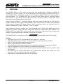
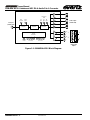
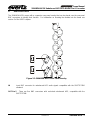
evertz 500AMDA‑AESU is a five output reclocking and auto equalizing AES Distribution Amplifier for unbalanced 75 ohm AES signals. It is also a high quality 24-bit audio Digital to Analog Converter (DAC).
The 500AMDA‑AESU automatically equalizes up to 1000m of Belden 1694A coax and provides 5 reclocked outputs. The 500AMDA-AESU also converts AES/EBU digital signal to 2 balanced analog audio outputs. The input sample rates supported are 32kHz, 44.1kHz and 48kHz. Analog audio output levels may be set individually from the front panel.


-
 1
1
-
 2
2
-
 3
3
-
 4
4
-
 5
5
-
 6
6
-
 7
7
-
 8
8
-
 9
9
-
 10
10
-
 11
11
-
 12
12


evertz 500AMDA‑AESU User manual
- Category
- Video line amplifiers
- Type
- User manual
evertz 500AMDA‑AESU is a five output reclocking and auto equalizing AES Distribution Amplifier for unbalanced 75 ohm AES signals. It is also a high quality 24-bit audio Digital to Analog Converter (DAC).
The 500AMDA‑AESU automatically equalizes up to 1000m of Belden 1694A coax and provides 5 reclocked outputs. The 500AMDA-AESU also converts AES/EBU digital signal to 2 balanced analog audio outputs. The input sample rates supported are 32kHz, 44.1kHz and 48kHz. Analog audio output levels may be set individually from the front panel.
Ask a question and I''ll find the answer in the document
Finding information in a document is now easier with AI
Related papers
Other documents
-
NXP MPC8535E Reference guide
-
-
-
-
-
-
-
Freescale Semiconductor MSC8144E Reference guide
-
-