Honeywell MS-9200UDLS User manual
- Category
- Fire protection
- Type
- User manual
This manual is also suitable for

Fire Alarm Control Panel
MS-9200UDLS
MS-9200UDLSE
PN: 52750:A ECN 05-680
IMPORTANT! The SLC Manual Document #51309 must be referenced in addition to this
manual when installing or servicing the Fire Alarm Control Panel.
Document #52750
11/04/05 Revision:
A

PrecauLarge.PMD 01/10/2005
An automatic fire alarm system–typically made up of smoke
detectors, heat detectors, manual pull stations, audible warn-
ing devices, and a fire alarm control panel with remote notifi-
cation capability–can provide early warning of a developing
fire. Such a system, however, does not assure protection
against property damage or loss of life resulting from a fire.
The Manufacturer recommends that smoke and/or heat de-
tectors be located throughout a protected premise following
the recommendations of the current edition of the National
Fire Protection Association Standard 72 (NFPA 72),
manufacturer's recommendations, State and local codes, and
the recommendations contained in the Guide for Proper Use
of System Smoke Detectors, which is made available at no
charge to all installing dealers. A study by the Federal Emer-
gency Management Agency (an agency of the United States
government) indicated that smoke detectors may not go off in
as many as 35% of all fires. While fire alarm systems are de-
signed to provide early warning against fire, they do not guar-
antee warning or protection against fire. A fire alarm system
may not provide timely or adequate warning, or simply may not
function, for a variety of reasons:
Smoke detectors may not sense fire where smoke cannot
reach the detectors such as in chimneys, in or behind walls, on
roofs, or on the other side of closed doors. Smoke detectors
also may not sense a fire on another level or floor of a build-
ing. A second-floor detector, for example, may not sense a
first-floor or basement fire.
Particles of combustion or "smoke" from a developing fire
may not reach the sensing chambers of smoke detectors be-
cause:
• Barriers such as closed or partially closed doors, walls, or
chimneys may inhibit particle or smoke flow.
• Smoke particles may become "cold," stratify, and not reach
the ceiling or upper walls where detectors are located.
• Smoke particles may be blown away from detectors by air
outlets.
• Smoke particles may be drawn into air returns before reaching
the detector.
The amount of "smoke" present may be insufficient to alarm
smoke detectors. Smoke detectors are designed to alarm at
various levels of smoke density. If such density levels are not
created by a developing fire at the location of detectors, the
detectors will not go into alarm.
Smoke detectors, even when working properly, have sensing
limitations. Detectors that have photoelectronic sensing
chambers tend to detect smoldering fires better than flaming
fires, which have little visible smoke. Detectors that have ion-
izing-type sensing chambers tend to detect fast-flaming fires
better than smoldering fires. Because fires develop in differ-
ent ways and are often unpredictable in their growth, neither
type of detector is necessarily best and a given type of detec-
tor may not provide adequate warning of a fire.
Smoke detectors cannot be expected to provide adequate
warning of fires caused by arson, children playing with
matches (especially in bedrooms), smoking in bed, and violent
explosions (caused by escaping gas, improper storage of
flammable materials, etc.).
Heat detectors do not sense particles of combustion and
alarm only when heat on their sensors increases at a prede-
termined rate or reaches a predetermined level. Rate-of-rise
heat detectors may be subject to reduced sensitivity over
time. For this reason, the rate-of-rise feature of each detector
should be tested at least once per year by a qualified fire pro-
tection specialist. Heat detectors are designed to protect
property, not life.
IMPORTANT! Smoke detectors must be installed in the
same room as the control panel and in rooms used by the
system for the connection of alarm transmission wiring, com-
munications, signaling, and/or power. If detectors are not so
located, a developing fire may damage the alarm system,
crippling its ability to report a fire.
Audible warning devices such as bells may not alert people
if these devices are located on the other side of closed or
partly open doors or are located on another floor of a building.
Any warning device may fail to alert people with a disability or
those who have recently consumed drugs, alcohol or medi-
cation. Please note that:
• Strobes can, under certain circumstances, cause seizures
in people with conditions such as epilepsy.
• Studies have shown that certain people, even when they
hear a fire alarm signal, do not respond or comprehend the
meaning of the signal. It is the property owner's responsi-
bility to conduct fire drills and other training exercise to
make people aware of fire alarm signals and instruct them
on the proper reaction to alarm signals.
• In rare instances, the sounding of a warning device can
cause temporary or permanent hearing loss.
A fire alarm system will not operate without any electrical
power. If AC power fails, the system will operate from standby
batteries only for a specified time and only if the batteries
have been properly maintained and replaced regularly.
Equipment used in the system may not be technically com-
patible with the control. It is essential to use only equipment
listed for service with your control panel.
Telephone lines needed to transmit alarm signals from a
premise to a central monitoring station may be out of service
or temporarily disabled. For added protection against tele-
phone line failure, backup radio transmission systems are rec-
ommended.
The most common cause of fire alarm malfunction is inade-
quate maintenance. To keep the entire fire alarm system in
excellent working order, ongoing maintenance is required per
the manufacturer's recommendations, and UL and NFPA stan-
dards. At a minimum, the requirements of NFPA 72 shall be
followed. Environments with large amounts of dust, dirt or
high air velocity require more frequent maintenance. A main-
tenance agreement should be arranged through the local
manufacturer's representative. Maintenance should be
scheduled monthly or as required by National and/or local
fire codes and should be performed by authorized profes-
sional fire alarm installers only. Adequate written records of
all inspections should be kept.
While a fire alarm system may lower insurance
rates, it is not a substitute for fire insurance!
Fire Alarm System Limitations

PrecauLarge.PMD 01/10/2005
WARNING - Several different sources of power can be con-
nected to the fire alarm control panel. Disconnect all sources
of power before servicing. Control unit and associated equip-
ment may be damaged by removing and/or inserting cards,
modules, or interconnecting cables while the unit is energized.
Do not attempt to install, service, or operate this unit until this
manual is read and understood.
CAUTION - System Reacceptance Test after Software
Changes. To ensure proper system operation, this product
must be tested in accordance with NFPA 72 after any pro-
gramming operation or change in site-specific software. Re-
acceptance testing is required after any change, addition or
deletion of system components, or after any modification,
repair or adjustment to system hardware or wiring.
All components, circuits, system operations, or software func-
tions known to be affected by a change must be 100% tested.
In addition, to ensure that other operations are not inadvert-
ently affected, at least 10% of initiating devices that are not
directly affected by the change, up to a maximum of 50 de-
vices, must also be tested and proper system operation veri-
fied.
This system meets NFPA requirements for indoor dry opera-
tion at 0-49° C/32-120° F
and at a relative humidity of 93 ±2%
RH (non-condensing) at 32 ±2°
C/90 ±3° F. However, the
useful life of the system's standby batteries and the elec-
tronic components may be adversely affected by extreme
temperature ranges and humidity. Therefore, it is recom-
mended that this system and all peripherals be installed in
an environment with a nominal room temperature of 15-27°
C/60-80° F.
Verify that wire sizes are adequate for all initiating and
indicating device loops. Refer to manual Specifications sec-
tion for maximum allowable I.R. drop from the specified de-
vice voltage.
Like all solid state electronic devices, this system may
operate erratically or can be damaged when subjected to
lightning-induced transients. Although no system is com-
pletely immune from lightning transients and interferences,
proper grounding will reduce susceptibility. Overhead or out-
side aerial wiring is not recommended, due to an increased
susceptibility to nearby lightning strikes. Consult with the
Technical Services Department if any problems are antici-
pated or encountered.
Disconnect AC power and batteries prior to removing or in-
serting circuit boards. Failure to do so can damage circuits.
Remove all electronic assemblies prior to any drilling, filing,
reaming, or punching of the enclosure. When possible, make
all cable entries from the sides or rear. Before making modifi-
cations, verify that they will not interfere with battery, trans-
former, and printed circuit board location.
Do not tighten screw terminals more than 9 in-lbs.
Over-tightening may damage threads, resulting in reduced
terminal contact pressure and difficulty with screw terminal
removal.
This system contains static-sensitive components.
Always ground yourself with a proper wrist strap before han-
dling any circuits so that static charges are removed from the
body. Use static-suppressive packaging to protect electronic
assemblies removed from the unit.
Follow the instructions in the installation, operating, and
programming manuals. These instructions must be followed
to avoid damage to the control panel and associated
equipment. FACP operation and reliability depend upon
proper installation by authorized personnel.
Adherence to the following will aid in problem-free
installation with long-term reliability:
WARNING: This equipment generates, uses, and can ra-
diate radio frequency energy and if not installed and used
in accordance with the instruction manual, may cause in-
terference to radio communications. It has been tested
and found to comply with the limits for class A computing
device pursuant to Subpart B of Part 15 of FCC Rules,
which is designed to provide reasonable protection against
such interference when operated in a commercial environ-
ment. Operation of this equipment in a residential area is
likely to cause interference, in which case the user will be
required to correct the interference at their own
expense.
Canadian Requirements
This digital apparatus does not exceed the Class A
limits for radiation noise emissions from digital
apparatus set out in the Radio Interference Regulations
of the Canadian Department of Communications.
Le present appareil numerique n'emet pas de bruits
radioelectriques depassant les limites applicables aux
appareils numeriques de la classe A prescrites dans le
Reglement sur le brouillage radioelectrique edicte par le
ministere des Communications du Canada.
FCC Warning
Installation Precautions

4 MS-9200UDLS PN 52750:A 11/04/05
Notes

MS-9200UDLS P/N: 52750:A 11/04/05 5
SECTION 1: Product Description ........................................................................................................................12
1.1: Features and Options...................................................................................................................................12
1.2: Specifications ..............................................................................................................................................13
1.2.1: Current Availability...........................................................................................................................15
1.3: Controls and Indicators ...............................................................................................................................16
1.4: Circuits ........................................................................................................................................................17
1.5: Digital Alarm Communicator/Transmitter..................................................................................................17
1.6: Components.................................................................................................................................................18
1.6.1: Intelligent Addressable Detectors: Newer Series..............................................................................18
1.6.2: Intelligent Addressable Modules: Newer Series...............................................................................19
1.6.3: 300 Series Intelligent Addressable Devices......................................................................................19
1.6.4: Addressable Device Accessories.......................................................................................................19
1.7: Optional Modules........................................................................................................................................20
1.8: Accessories..................................................................................................................................................20
1.8.1: PK-CD Programming Utility ............................................................................................................20
1.8.2: Dress Panel........................................................................................................................................20
1.8.3: Battery Box .......................................................................................................................................21
1.8.4: Battery Charger.................................................................................................................................21
1.8.4.1 CHG-75 Battery Charger ........................................................................................................21
1.8.4.2 CHG-120F Battery Charger ....................................................................................................21
1.8.5: Annunciators .....................................................................................................................................22
1.9: Getting Started.............................................................................................................................................23
1.10: Telephone Requirements and Warnings ....................................................................................................24
1.10.1: Telephone Circuitry.........................................................................................................................24
1.10.2: Digital Communicator.....................................................................................................................24
1.10.3: Telephone Company Rights and Warnings .....................................................................................25
1.10.4: For Canadian Applications..............................................................................................................26
SECTION 2: Installation .......................................................................................................
................................27
2.1: Mounting Backbox......................................................................................................................................27
2.2: Mounting Transformer ................................................................................................................................28
2.3: Power...........................................................................................................................................................31
2.3.1: AC Power and Earth Ground Connection.........................................................................................31
2.3.2: Battery Power....................................................................................................................................31
2.3.3: Special Application DC Power Output Connection..........................................................................31
2.4: Relays..........................................................................................................................................................32
2.5: Notification Appliance Circuits ..................................................................................................................32
2.5.1: Configuring NACs ............................................................................................................................33
2.5.2: Style Y (Class B) NAC Wiring .........................................................................................................33
2.5.3: Style Z (Class A) NAC Wiring ........................................................................................................34
2.6: Remote Synchronization Output .................................................................................................................34
2.7: UL Power-limited Wiring Requirements ....................................................................................................35
2.8: Digital Communicator.................................................................................................................................36
2.9: Optional Module Installation ......................................................................................................................37
2.9.1: 4XTMF Transmitter Module Installation..........................................................................................38
2.9.2: Printer/PC..........................................................................................................................................40
2.9.3: Digital Communicator and Annunciators .........................................................................................41
2.9.3.1 ACM-8RF Relay Control Module ..........................................................................................41
2.9.3.2 ACS and AFM Series Annunciators .......................................................................................41
SECTION 3: Programming ..................................................................................................................................42
3.1: Programming Data Entry ............................................................................................................................42
3.2: User Programming ......................................................................................................................................43
3.3: Initial Power-up...........................................................................................................................................44
Table of Contents

Table of Contents
6
MS-9200UDLS P/N: 52750:A 11/04/05
3.4: Programming Screens Description..............................................................................................................44
3.5: Programming and Passwords ......................................................................................................................44
3.6: Master Programming Level.........................................................................................................................46
3.6.1: Autoprogram .....................................................................................................................................47
3.6.2: Point Program....................................................................................................................................48
3.6.2.1 Detector Programming ............................................................................................................48
3.6.2.1.1 Add Detector ........................................................................................................................48
3.6.2.1.2 Delete Detector .....................................................................................................................49
3.6.2.1.3 Edit Detector ........................................................................................................................49
3.6.2.2 Module Programming .............................................................................................................58
3.6.2.2.1 Add Module .........................................................................................................................58
3.6.2.2.2 Delete Module ......................................................................................................................59
3.6.2.2.3 Edit Module Screen for Monitor Module .............................................................................59
3.6.2.2.4 Edit Module Screen for Control Modules ............................................................................68
3.6.3: Zone Setup.........................................................................................................................................75
3.6.3.1 Enable ......................................................................................................................................75
3.6.3.2 Disable .....................................................................................................................................76
3.6.3.3 Zone 97, 98 and 99 ..................................................................................................................76
3.6.3.4 Zones Installed ........................................................................................................................77
3.6.3.5 Zones Enabled .........................................................................................................................77
3.6.3.6 Zones Disabled ........................................................................................................................77
3.6.3.7 Zone Type ...............................................................................................................................78
3.6.3.8 Zones Available ......................................................................................................................79
3.6.4: Loop Setup ........................................................................................................................................79
3.6.4.1 Style .........................................................................................................................................79
3.6.4.2 Loop Protocol ..........................................................................................................................79
3.6.5: System Setup.....................................................................................................................................80
3.6.5.1 Trouble Reminder ...................................................................................................................81
3.6.5.2 Banner .....................................................................................................................................81
3.6.5.3 Time-Date ...............................................................................................................................82
3.6.5.3.1 Time .....................................................................................................................................82
3.6.5.3.2 Date ......................................................................................................................................83
3.6.5.3.3 Clock Format ........................................................................................................................83
3.6.5.3.4 Daylight Savings Time .........................................................................................................83
3.6.5.4 Timers .....................................................................................................................................84
3.6.5.4.1 PAS (Positive Alarm Sequence) Delay ................................................................................84
3.6.5.4.2 Pre-signal Delay ...................................................................................................................85
3.6.5.4.3 Waterflow Delay ..................................................................................................................85
3.6.5.4.4 AC Loss Delay .....................................................................................................................86
3.6.5.5 NAC (Notification Appliance Circuit) ....................................................................................86
3.6.5.5.1 Enabled .............................................................................................................
....................87
3.6.5.5.2 Type ......................................................................................................................................88
3.6.5.5.3 Silenceable ...........................................................................................................................88
3.6.5.5.4 Auto Silence .........................................................................................................................89
3.6.5.5.5 Coding (only for NACs not programmed as Sync Strobe Type) .........................................89
3.6.5.5.6 Zone ......................................................................................................................................91
3.6.5.5.7 Silence Inhibited ...................................................................................................................91
3.6.5.5.8 Sync Type .............................................................................................................................91
3.6.5.6 Relays ......................................................................................................................................92
3.6.5.7 Canadian Option ......................................................................................................................93
3.6.5.8 Waterflow Silenceable ............................................................................................................93
3.6.6: Verify Loop .......................................................................................................................................93
3.6.7: History...............................................................................................................................................94
3.6.7.1 View Events ............................................................................................................................94
3.6.7.2 Erase History ...........................................................................................................................94
3.6.8: Walktest.............................................................................................................................................95

MS-9200UDLS P/N: 52750:A 11/04/05 7
Table of Contents
3.6.9: Option Modules................................................................................................................................96
3.6.9.1 Annunciators/UDACT ............................................................................................................96
3.6.9.2 Onboard DACT .......................................................................................................................97
3.6.9.2.1 Onboard DACT Enable ........................................................................................................97
3.6.9.2.2 Primary Phone ......................................................................................................................98
3.6.9.2.3 Secondary Phone ..................................................................................................................98
3.6.9.2.4 Service Terminal ..................................................................................................................99
3.6.9.2.5 Central Station ......................................................................................................................101
3.6.9.2.6 Trouble Call Limit (Dialer Runaway Prevention) ...............................................................102
3.6.9.2.7 Manual Dial Mode ...............................................................................................................114
3.6.9.3 Printer/PC ................................................................................................................................115
3.6.10: Password Change ............................................................................................................................116
3.6.11: Clear Program .................................................................................................................................117
3.6.12: Program Check................................................................................................................................118
3.7: Maintenance Programming Level ...............................................................................................................120
3.7.1: Disable Point .....................................................................................................................................121
3.7.2: History...............................................................................................................................................122
3.7.3: Program Check..................................................................................................................................123
3.7.4: Walktest.............................................................................................................................................124
3.7.5: System...............................................................................................................................................124
3.7.6: Zone Setup ........................................................................................................................................126
SECTION 4: Operating Instructions ....................................................................................................................128
4.1: Panel Control Buttons .................................................................................................................................128
4.1.1: Acknowledge/Step ............................................................................................................................128
4.1.2: Alarm Silence....................................................................................................................................128
4.1.3: Drill/Hold 2 Sec ................................................................................................................................128
4.1.4: Reset..................................................................................................................................................128
4.2: LED Indicators ............................................................................................................................................129
4.3: Normal Operation........................................................................................................................................130
4.4: Trouble Operation .......................................................................................................................................130
4.5: Alarm Operation..........................................................................................................................................132
4.6: Supervisory Operation.................................................................................................................................133
4.7: Process Monitor Operation..........................................................................................................................134
4.8: Hazard/Tornado Condition Operation.........................................................................................................134
4.9: Medical Alert Condition Operation.............................................................................................................134
4.10: NAC Operation .........................................................................................................................................134
4.11: Programmed Zone Operation ....................................................................................................................135
4.12: Disable/Enable Operation .........................................................................................................................135
4.13: Waterflow Circuits Operation ...................................................................................................................135
4.14: Detector Functions .......................................................................................................
.............................135
4.15: Time Functions: Real-Time Clock ............................................................................................................135
4.16: Synchronized NAC Operation ..................................................................................................................136
4.17: Coded Operation .......................................................................................................................................136
4.18: Presignal....................................................................................................................................................136
4.19: Positive Alarm Sequence ..........................................................................................................................137
4.20: Special System Timers ..............................................................................................................................138
4.20.1: Silence Inhibit Timer.......................................................................................................................138
4.20.2: Autosilence Timer...........................................................................................................................138
4.20.3: Trouble Reminder ...........................................................................................................................138
4.20.4: Waterflow Retard Timer..................................................................................................................138
4.20.5: Alarm Verification (None or One Minute)......................................................................................139
4.21: Walktest.....................................................................................................................................................139
4.22: Read Status................................................................................................................................................140
4.22.1: System Point ...................................................................................................................................141

Table of Contents
8
MS-9200UDLS P/N: 52750:A 11/04/05
4.22.2: Zones ...............................................................................................................................................142
4.22.3: Power...............................................................................................................................................143
4.22.4: Trouble Reminder............................................................................................................................144
4.22.5: Timers..............................................................................................................................................144
4.22.6: NAC ................................................................................................................................................145
4.22.7: Relays..............................................................................................................................................145
4.22.8: Program Check................................................................................................................................146
4.22.9: History.............................................................................................................................................146
4.22.10: Annunciators .................................................................................................................................147
4.22.11: Phone Line.....................................................................................................................................147
4.22.12: Central Station...............................................................................................................................148
4.22.13: Service Terminal............................................................................................................................149
4.22.14: Printer/PC......................................................................................................................................149
4.22.15: Print ...............................................................................................................................................150
4.22.16: Time-Date......................................................................................................................................152
SECTION 5: Central Station Communications ...................................................................................................153
5.1: Transmittal Priorities ...................................................................................................................................156
SECTION 6: Remote Site Upload/Download .......................................................................................................158
6.1: Downloading Program.................................................................................................................................158
6.1.1: Security Features...............................................................................................................................159
6.2: Downloading Initiated at a Service Terminal..............................................................................................161
6.3: Uploading Initiated at a Service Terminal...................................................................................................162
SECTION 7: Power Supply Calculations .............................................................................................................163
7.1: Overview .....................................................................................................................................................163
7.2: Calculating the AC Branch Circuit..............................................................................................................163
7.3: Calculating the System Current Draw.........................................................................................................164
7.3.1: Overview ...........................................................................................................................................164
7.3.2: How to Use Table 7.3 on page 165 to Calculate System Current Draw ...........................................164
7.4: Calculating the Battery Size ........................................................................................................................166
7.4.1: NFPA Battery Requirements .............................................................................................................166
7.4.2: Selecting and Locating Batteries.......................................................................................................166
APPENDIX A: Software Zones ............................................................................................................................167
A.1: Correlations ...............................................................................................................................................167
APPENDIX B: Default Programming .................................................................................................................173
APPENDIX C: NFPA Standard-Specific Requirements ...................................................................................174
APPENDIX D: Wire Requirements .....................................................................................................................178
APPENDIX E: HVAC Control .............................................................................................................................179
E.1: Control Module Operation .........................................................................................................................179
E.1.1: HVAC SHUTDN .............................................................................................................................179
E.2: Monitor Module Operation ........................................................................................................................179
E.2.1: HVAC RESTART ...........................................................................................................................179
E.2.2: HVAC OVRRIDE ...........................................................................................................................180

MS-9200UDLS PN 52750:A 11/04/05 9
It is imperative that the installer understand the requirements of the Authority Having Jurisdiction
(AHJ) and be familiar with the standards set forth by the following regulatory agencies:
• Underwriters Laboratories Standards
• NFPA 72 National Fire Alarm Code
• CAN/ULC - S527-99 Standard for Control Units for Fire Alarm Systems
NFPA Standards
NFPA 72 National Fire Alarm Code
NFPA 70 National Electrical Code
Underwriters Laboratories Documents:
UL 38 Manually Actuated Signaling Boxes
UL 217 Smoke Detectors, Single and Multiple Station
UL 228 Door Closers–Holders for Fire Protective Signaling Systems
UL 268 Smoke Detectors for Fire Protective Signaling Systems
UL 268A Smoke Detectors for Duct Applications
UL 346 Waterflow Indicators for Fire Protective Signaling Systems
UL 464 Audible Signaling Appliances
UL 521 Heat Detectors for Fire Protective Signaling Systems
UL 864 Standard for Control Units for Fire Protective Signaling Systems
UL 1481 Power Supplies for Fire Protective Signaling Systems
UL 1610 Central Station Burglar Alarm Units
UL 1638 Visual Signaling Appliances
UL 1971 Signaling Devices for Hearing Impaired
CAN/ULC - S524-01 Standard for Installation of Fire Alarm Systems
Other:
EIA-232E Serial Interface Standard
EIA-485 Serial Interface Standard
NEC Article 250 Grounding
NEC Article 300 Wiring Methods
NEC Article 760 Fire Protective Signaling Systems
Applicable Local and State Building Codes
Requirements of the Local Authority Having Jurisdiction (LAHJ)
Fire-Lite Documents:
Fire-LiteDevice Compatibility Document #15384
SLC Wiring Manual Document #51309
AFM-16ATF & AFM-32AF Document #15970
AFM-16AF Annunciator Document #15210
ACS Series Annunciators Document #51480
CHG-120F Battery Charger Document #50888
CHG-75 Battery Charger Document #51315
LDM Series Lamp Driver Modules Document #50055
LCD-80F Remote Fire Annunciator Document #51338
ACM-8RF Relay Control Module Document #50362
This product has been certified to comply with the requirements in the Standard for Control Units and Accessories for Fire
Alarm Systems, UL 864, 9th Edition. Operation of this product with products not tested for UL 864, 9th Edition has not
been evaluated. Such operation requires the approval of the local Authority Having Jurisdiction (AHJ).
Before proceeding, the installer should be familiar with the following documents.

10 MS-9200UDLS PN 52750:A 11/04/05
PS2 Keyboard Interface DACT Phone Line Jacks
(Nonpower-Limited)
DB9F
Resettable Power - 24 VDC filtered, power-limited
(0.500 amps maximum) to smoke detectors (IDC).
Supervision required.
Nonresettable or Resettable Power
Jumper selectable by JP4, 24 VDC filtered,
power-limited (0.500 amps maximum)
Supervision required. Nonresettable
Power suitable for powering annunciators,
Resettable Power suitable for powering
smoke detectors..
NAC #1 & #2
Style Z (Class A)
2.5 amps max. per circuit.
JP6 configured for Class A
using NACKEY card.
(Supervised, Power Limited)
NAC #1
NAC #2
NAC #1, #2, #3 & #4, Style Y (Class B) (Supervised, Power Limited)
(Special Application) 2.5 amps max. per circuit. JP6 configured
for Class B using NACKEY card.
(See Style Z illustrated near right edge of board).
Nonsupervised relay contacts
Contact Ratings:
2.0 amps @ 30 VDC (resistive)
0.5 amps @ 30 VAC (resistive)
Contacts shown below in normal
condition (AC power with no alarm,
trouble or supervisory activity).
A Fail Safe Trouble
relay switches to the
NO position during
trouble conditions and
under loss of all power.
(nonsupervised)
For EDP-listed equipment or
personal computer with FACP
Upload/Download Utility.
50 foot maximum within same room.
(supervised)
Refer to the SLC Wiring
Manual for detailed
information on wiring
addressable devices
for Style 4, 6 and 7.
ACS (EIA-485)
to ACS Annunc.
(power-limited,
supervised)
ELRs 4.7K, ½W
Special Application DC Power Outputs (24 VDC)
Nonsupervised, power-limited circuits
Supervise with a power supervision relay A77-716B
Battery
Basic System Connections
Notification Appliance Circuits
Notification Appliance Circuits
2 Programmable Relays &
1 Fixed Trouble Relay
EIA-232
to printer or
personal computer
SLC Loop
OR
OR
B
+
B
+
B
-
B
-
A
+
A
+
A
-
A
-
NO NC C NC NO CNO NC C
Alarm*
Trouble
Supervisory*
5 4 3 2 1
9 8 7 6
Green
Black
White
Red
T
X
R
C
V
TB8 (option to DB-25)
TB3
TB8
TB8
TB4
5 4 3 2 1
25 24 23 22 21 20 19 18 17 16 15 14
9 8 7 613 12 11 10
CAUTION! HIGH VOLTAGE
NC NO C
+
+
+
+
+
+
120 VAC, 60 HZ, 3.0 amps
220/240 VAC, 50 Hz, 1.5 amps
24 VDC, supervised,
nonpower-limited
18 Amp Hour maximum
T
X
R
C
V
D
T
R
G
N
D
G
N
D
+ 24V -
NON-RST
POWER
+ 24V -
RST
POWER
REMOT E PWR
SUPPLY SYNC NAC 1 CLAS S A
NAC 1 & 3 CLASS B
NAC 2 CLA SS A
NAC 2 & 4 CLASS B
RELAY 3
RELAY 1
HOT NEUT EARTH
- +
BATTERY
LCD DISPLAY
REMOVE TO
DISABLE GND. FLT.
CUT TO
MONITOR
4XTMF
KISSOFF
PRI. ACTIVE
SEC. ACTIVE
SEC. PHONE LINE
PRI. PHONE LINE
4XTMF
MINI DIN
KEYBOARD CONN.
KEYPAD
I/F
RELAY 2
TRANSFORMER 1
TRANSFORMER 2
+ -
B+ A+ A- B- B+ A+ A- B-
1B+ 3B+ 3B- 1B- 2B+ 4B+ 4B- 2B-
NO NC C
NO NC C NO NC C
B+ A + B- A- A B
ACS
SHIELDSL CSLC
SLCSLC
OUT+ IN+ OUT- IN-
TB5
TB6 TB8 TB9 TB10
JP2
JP3
SW1
JP7
JP5
JP6
1
2
3
TB11
J10
J3
J13 J12
J7
J5
J1
J4
J9
J6
J11
CAUTION!
HIGH VOLTAGE
(* )Factory default relay programming
shield
B
+
B
-
BA
+
A
-
A
TERM
(EIA-485)
to LCD-80F
I
N
+
O
U
T
+
I
N
-
O
U
T
-
+
-
Remove this jumper
to disable the FACP
battery charger when
using external charger.
Transformer 2 Connector
Transformer 1 Connector
Flash Memory Load Enable Switch.
UP is normal position for switch.
DOWN position allows loading of
factory software upgrades.
Cut this jumper to enable
Supervisory relay when
4XTMF module is installed
Cut this jumper to supervise
the 4XTMF module when
installed (see J5 & J6)
To disable ground fault detection,
remove jumper/shunt from JP7
Configure NACs for Class A or
Class B wiring using NACKEY
card. Factory default is Class B.
NAC #1 NAC #3
NAC
Number
-
++
+
+
B
+
B
-
1
1
B
+
B
-
33
NAC #4 NAC #2
B
+
B
-
++
++
++
B
+
B
-
2244
TB3
TB4 TB7
2
1
2
1
4
3
+ +
- -
TB1
TB2
JP4
+
-
+
+
D
T
R
Remote Synchronization Output
Special Application Power
24 VDC filtered, supervised and power-limited.
0.040 amps maximum, follows NAC1 control circuit.
Requires 4.7kohm End-of-Line resistor.
Important!
voids
only
Removing Ground
Fault Disable Jumper JP7
UL/NFPA Style/Class
identifications for circuits.
Remove jumper JP7
with the approval of the AHJ
(Authority Having Jurisdiction)

MS-9200UDLS PN 52750:A 11/04/05 11
Peripheral Devices and Their Documents:
LCD-80F
Doc. #51338
AFM-16AF
Doc. #15210
LDM-32F
Doc. #50055
AFM-16ATF &
AFM-32AF
Doc. #15970
ACS Series
51480
ACM-8RF
Doc. #50362
Addressable Devices and SLC Wiring
Doc. #51309
CHG-120F Charger
Doc. #50888
TERM (EIA-485)
Annunciators
ACS (EIA-485)
Annunciators
SLC Loop
Battery Connector
92udperi.cdr
CHG-75 Charger
Doc. # 51315

Product Description Features and Options
12 MS-9200UDLS PN 52750:A 11/04/05
SECTION 1 Product Description
The Fire-LiteMS-9200UDLS is a combination FACP (Fire Alarm Control Panel) and
DACT (Digital Alarm Communicator/Transmitter) all on one circuit board. This
compact, cost effective, intelligent addressable control panel has an extensive list of
powerful features. The combination of Fire-Lite’s newer series devices and legacy 300
Series devices, along with the MS-9200UDLS FACP, offer the latest in fire protection
technology. The power supply and all electronics are contained on a single circuit
board housed in a metal cabinet, providing a complete fire control system for most
applications. Optional modules, which plug into the main circuit board, are available
for special functions. Available accessories include LED, graphic and LCD
annunciators, reverse polarity/city box transmitter, local and remote upload/download
software and remote power expansion.
The integral DACT transmits system status (alarms, troubles, AC loss, etc.) to a Central
Station via the public switched telephone network. It also allows remote and local
programming of the control panel using the PK-CD Upload/Download utility. In
addition, the control panel may be programmed or interrogated off-site via the public
switched telephone network. Any personal computer with Windows
™
95 or greater,
and compatible modem with a speed of 14.4 kbps or faster and Fire•Lite Upload/
Download software kit PK-CD, may serve as a Service Terminal. This allows
download of the entire program or upload of the entire program, history file, walktest
data, current status and system voltages.
MS-9200UDLS is used in this manual to refer to both the MS-9200UDLS and the MS-
9200UDLSE FACPs (Fire Alarm Control Panels).
Inventory
When the MS-9200UDLS shipment is received, check to make certain that all parts
have been included in the shipment. The MS-9200UDLS shipment should consist of
one of each of the following:
main circuit board with display
backbox with door
plastic bag containing screws, cables, key, etc.
manual
1.1 Features and Options
• New LiteSpeed™ polling protocol for faster SLC response time
• SLC operates up to 10,000 ft. (3,000 m) with twisted, unshielded wire (refer to
"Wire Requirements" on page 178)
• Built-in DACT (Digital Alarm Communicator/Transmitter)
• Single addressable SLC loop which meets NFPA Style 4, 6 and 7 requirements
• 198 addressable device capacity (99 detectors and 99 control/relay/monitor
modules)
• 99 software zones
• Onboard NACs (Notification Appliance Circuits) which can be configured as
four Style Y (Class B) or two Style Z (Class A) circuits - special application
• 3.0 amps total power for NACs and 24 VDC special application auxiliary power
outputs expandable to 6.0 amps
• 3.6 amps total system power (includes battery charger) expandable to 6.6 amps
• Two programmable relay outputs and one fixed trouble relay
• Synchronization output for remote power supply applications (special
application)
• Built-in Programmer

Specifications Product Description
MS-9200UDLS PN 52750:A 11/04/05 13
• Telephone Line Active LEDs
• Communication Confirmation (Kissoff) LED
• Touchtone/Rotary dialing
• Programmable Make/Break Ratio
• EIA-232 Printer/PC interface (variable baud rate)
• 80-character LCD display (backlit)
• Real-time clock/calendar with daylight savings time control
• History file with 1,000 event capacity
• Advanced fire technology features:
Automatic drift compensation
Maintenance alert
Detector sensitivity test capability (NFPA 72 compliant)
Automatic device type-code verification
Point trouble identification
• Waterflow selection per module point
• Alarm verification selection per detector point
• Walktest, silent or audible
• PAS (Positive Alarm Sequence) and Pre-signal per point (NFPA 72 compliant)
• Silence inhibit timer option per NAC
• Autosilence timer option per NAC
• Continuous, March Time, Temporal or California code for main circuit board
NACs with two-stage capability
• Selectable strobe synchronization per NAC
• Remote Acknowledge, Alarm Silence, Reset and Drill via addressable modules,
AFM annunciators or LCD-80F Remote annunciator
• Auto-program (learn mode) reduces installation time. Reports two devices set to
the same address
• Password and key-protected nonvolatile memory
• User programmable password
• Fully programmable from local keypad or optional keyboard
• Upload/Download (local or remote) of program and data via integral DACT
• Compatible with Fire-Lite’s newer series devices (refer to SLC Wiring Manual
for a list of compatible addressable devices)
• Compatible with legacy Fire-Lite 300 Series devices in CLIP mode only (refer to
the SLC Wiring Manual for a list of compatible addressable devices)
• Optional 4XTMF module (conventional reverse polarity/city box transmitter)
• Annunciators:
ACS Series-LED Zone Annunciators
LDM Graphic Annunciator Series
LCD-80F Liquid Crystal Display point annunciator
ACM-8RF Relay Module
1.2 Specifications
Refer to Illustration on page 10 for terminal locations and connections.
AC Power - TB11
MS-9200UDLS: 120 VAC, 60 Hz, 3.0 amps
MS-9200UDLSE: 240 VAC, 50 Hz, 1.5 amps
Wire size: minimum 14 AWG (2.00 mm
2
) with 600 V insulation

Product Description Specifications
14 MS-9200UDLS PN 52750:A 11/04/05
Battery (Lead Acid Only) - J9
Maximum Charging Circuit: Normal Flat Charge - 27.6 VDC @ 0.80 amp
Maximum Battery Charger Capacity: 18 Amp Hour (MS-9200UDLS cabinet holds
maximum of two 18 Amp Hour batteries. For greater than 25 Amp Hour up to 120
Amp Hour batteries, use the CHG-75 or CHG-120F Battery Charger and BB-55F
Battery Box.
Note: Jumper JP5, on the FACP main circuit board, must be removed to disable the
FACP battery charger when using an external battery charger.
Communication Loop - TB10
24 VDC nominal, 27.6 VDC maximum
Maximum length is 10,000 ft. (3,000 m) total twisted, shielded pair length or 3,000 ft.
(900 m) untwisted, unshielded pair length
Maximum loop current is 400 mA (short circuit) or 100 mA (normal)
Maximum loop resistance is 40 ohms
Supervised and power-limited circuit requires ferrite bead per FCC requirement
Refer to SLC Loop manual for wiring information
Notification Appliance Circuits - TB3 & TB4
Each Terminal Block provides connections for two Style Y (Class B) or one Style Z
(Class A) for a total of Four Style Y (Class B) or two Style Z (Class A) NACs
Style is configured using NACKEY card plugged into JP6 on main board
Special Application full-wave rectified power
Power-limited circuitry
Maximum voltage drop in wiring: 2.0 VDC
Nominal operating voltage: 24 VDC
Current-limit: fuseless, electronic, power-limited circuitry
Maximum signaling current per circuit: 2.5 amps (see Figure 1.1 on page 15)
End-of-Line Resistor: 4.7 kΩ, ½ watt (P/N 71252 UL listed) for Style Y (Class B) NAC
Refer to the Device Compatibility Document for listed compatible devices
Two Programmable Relays and One Fixed Trouble Relay - TB5, TB6 & TB7
Contact rating: 2.0 amps @ 30 VDC (resistive), 0.5 amps @ 30 VAC (resistive)
Form-C relays
Refer to Figure 2.6 on page 32 for information on power-limited relay circuit wiring
Nonresettable Special Application Power (24 VDC Nominal) -
TB1, Terminals 1 (+) & 2 (-)
Jumper selectable (JP4) for conversion to resettable power output
Maximum ripple voltage: 10mV
RMS
Total DC current available from each output is up to 0.5 amps (see Figure 1.1)
Power-limited circuit requires ferrite bead per FCC requirements
Four-Wire Resettable Special Application Smoke Detector Power (24 VDC
nominal) - TB3, Terminals 3 (+) & 4 (-)
Maximum ripple voltage: 10 mV
RMS
Up to 0.5 amps is available for powering 4-wire smoke detectors (see Figure 1.1)
Power-limited circuit requires ferrite bead per FCC requirements
Refer to the Device Compatibility Document for listed compatible devices
Remote Sync Output - TB2
Remote power supply synchronization output
24 VDC nominal special application power
Maximum current is 40 mA
End-of-Line Resistor: 4.7KΩ
Output linked to NAC 1 control
Supervised and power-limited circuit requires ferrite bead per FCC requirements

Specifications Product Description
MS-9200UDLS PN 52750:A 11/04/05 15
EIA-485 (TERM) or EIA-232 (ACS) - TB8
EIA-485 Terminal Mode annunciator connections: Terminal 1 (Out +), 2 (In +),
3 (Out -), 4 (In -)
EIA-232 PC/Printer applications connections: Terminal 1 (Transmit), 2 (Receive),
3 (Ground)
EIA-485 (ACS) - TB9
ACS annunciator connector, Terminal 1 (+) and Terminal 2 (-), requires ferrite bead
1.2.1 Current Availability
The following figure illustrates the maximum current that is possible for each panel
circuit and the total current available from the FACP with optional second transformer.
Figure 1.1 Current Availability
owerdist9200ud.cdr
Refer to the battery calculations section for additional information.
Note: If NACs are
configured as two Style Z
(Class A) circuits, each
circuit can handle 2.5
amps maximum.
6.0 amps with optional second
XRM-24(E) transformer.
3.0 amps max. with only
standard transformer installed.

Product Description Controls and Indicators
16 MS-9200UDLS PN 52750:A 11/04/05
1.3 Controls and Indicators
LCD Display
The FACP uses an 80-character
(4 lines X 20 characters) high
viewing angle LCD display. The
display includes a long life LED
backlight that remains illuminated. If
AC power is lost and the system is
not in alarm, the LED backlight will turn off to conserve batteries.
LED Indicators
LED indicators are provided to annunciate the following conditions:
• AC Power (green)
• Fire Alarm (red)
• Supervisory (yellow)
• Trouble (yellow)
• Maintenance/presignal (yellow)
• Alarm Silenced signals (yellow)
• Disabled (yellow)
• Battery fault (yellow)
• Ground fault (yellow)
Key Panel
Mounted on the main circuit board, the key panel includes a window for the LCD
display and LED indicators as listed above. The key panel, which is visible with the
cabinet door closed, has 25 keys, including a 16 key alpha-numeric pad similar to a
telephone keypad.
Function keys:
• Acknowledge/Step
• Alarm Silence
• Drill
• Reset (lamp test)
Service/program keys:
• Keys labeled 1 to 9
• * key
• # key
• 0 (recall) key
•1st Event key
• Clear key
• Escape key
• Mode key
• Four cursor keys (up, down, left and right)
• Enter key
Local Piezo Sounder
A piezo sounder provides separate and distinct pulse rates for alarm, trouble and
supervisory conditions.
HONEYWELL LIFE SAFETY
SYSTEM ALL NORMAL
10:00A 012102
1
4
*
2
5
0
3
6
#
1
st
EVENT
ABC
DEF
GHI
JKL
MNO
PRS
TUV WXY
QZ
-/.
CLR
78 9
ESC
ENTER
RECALL
ACK/STEP
ALARM
SILENCE
DRILL
HOLD 2 SEC
RESET
MODE
MAINTENA NCE
ALARM
SILENCED
DISABLED
BATTERY
GROUND
SUPERVISORY
TROUBLE
AC POWER
FIRE ALARM
Figure 1.2 Membrane/Display Panel
9600kypd.cdr

Circuits Product Description
MS-9200UDLS PN 52750:A 11/04/05 17
1.4 Circuits
SLC Communication Loop
One SLC loop is provided standard on the FACP main circuit board. The SLC loop,
configurable for NFPA Style 4, 6 or 7, provides communication to addressable
detectors, monitor (initiating device) and control (output device) modules. Refer to the
SLC Wiring manual for information on wiring devices.
Output Circuits
The following output circuits are available on the FACP:
• Special Application Power
24 VDC Resettable (smoke detector power) output - 0.5 amps maximum
24 VDC Nonresettable or Resettable power output - 0.5 amps maximum
• 24 VDC Battery Charger (up to 18 AH batteries)
NAC (Notification Appliance Circuits)
NACs configurable for four Style Y (Class B) or two Style Z (Class A) using NACKEY
card in JP6, are provided with various programmable features.
Relays
One fixed and two fully programmable Form-C dry contact relays are provided. The
fixed fail-safe relay monitors system trouble and the two programmable relays are
factory default programmed for system alarm and system supervisory. Contacts are
rated 2.0 amps @ 30 VDC (resistive) and 0.5 amps @ 30 VAC (resistive). The
programmable relays can be programmed for the following operations:
• fire alarm
• trouble
• supervisory
• supervisory auto-resettable
• DACT communication failure
• process monitor
• process monitor auto-resettable
• hazard alert
• medical alert
•AC loss
1.5 Digital Alarm Communicator/Transmitter
Two modular phone jacks allow easy connection to telephone lines. Modular jacks are
labeled PH1 for Primary Phone Line and PH2 for Secondary Phone Line. Two
telephone line active red LEDs are provided as well as a green Kissoff LED. The
integral digital communicator provides the following functions:
• Line Seizure: takes control of the phone lines disconnecting any premises phones
• Off/On Hook: performs on and off-hook status to the phone lines
• Listen for dial tone: 440 Hz tone typical in most networks
• Dialing the Central Station(s) number: default is Touch-Tone
®
, programmable to
rotary
• For tone burst or touchtone type formats: discern proper Ack and Kissoff tone(s).
The frequency and time duration of the tone(s) varies with the transmission
format. The control panel will adjust accordingly.
• Communicate in the following formats:
12 Tone Burst types: 20 pps
(3+1, 4+1, 4+2, 3+1 Exp., 4+1 Exp., 4+2 Exp.)
3 Touchtone Types
4+1 Ademco Express
4+2 Ademco Express
Ademco Contact ID
Reference
Manual

Product Description Components
18 MS-9200UDLS PN 52750:A 11/04/05
1.6 Components
Main Circuit Board
The main circuit board contains the system’s CPU, power supply, other primary
components and wiring interface connectors. The 4XTMF option module plugs in and
is mounted to the main circuit board.
Cabinet
The MS-9200UDLS backbox provides space for two batteries (up to 18 Amp Hour).
Ample knockouts are provided for system wiring. Also available is an optional dress
panel (DP-9692), which mounts to the inside of the cabinet (required by ULC for
Canadian installations). The dress panel must be installed to meet FM requirements.
Transformer Assembly
One 100VA transformer is provided standard
with the panel (3.6 amps maximum). An
optional 100 VA transformer XRM-24
(XRM-24E for the MS-9200UDLSE) is
available to provide maximum system and
accessory power (6.6 amp total).
Batteries
The MS-9200UDLS cabinet provides space
for two batteries (up to 18 Amp Hour).
Batteries larger than 18 Amp Hour require an
external charger such as the CHG-75 or
CHG-120F and a UL listed battery box such
as the BB-55F. Batteries must be ordered
separately.
1.6.1 Intelligent Addressable Detectors: Newer Series
Intelligent, addressable detectors provide information to the control panel on an SLC
Signaling Line Circuit (refer to the SLC Wiring Manual for detailed information on
device installation, wiring and operation). This allows the control panel to continually
process the information to determine the status (alarm, trouble, maintenance or normal)
of each detector. Each detector responds to an SLC address that is set in the detector
head using built-in rotary decimal switches. The maximum address cannot exceed
address 99. Note that a blinking LED on an intelligent detector indicates
communication between the detector and the control panel.
These devices (350 Series or newer) can operate in CLIP mode (Classic Loop Interface
Protocol) or LiteSpeed mode to provide a quicker response. They are also compatible
with older 300 Series devices. If a mix of old and new series devices are installed on
the same loop, the FACP must be programmed to operate in CLIP mode. Refer to the
SLC Wiring Manual for a list of compatible addressable detectors.
See Page
Standard
XRM-24(E)
Optional
XRM-24(E)
9200xfor.cdr
-
-
+
+
Battery Cable P/N 75287
9200batt.cdr

Components Product Description
MS-9200UDLS PN 52750:A 11/04/05 19
1.6.2 Intelligent Addressable Modules: Newer Series
The newer series of Control Modules and Monitor Modules provide an interface
between the control panel and conventional notification and initiating devices. Each
module can be set to respond to an address with built-in rotary switches. The maximum
address cannot exceed address 99. Note that a blinking LED on an addressable module
indicates communication between the module and the control panel.
These devices (350 Series or newer) can operate in CLIP mode (Classic Loop Interface
Protocol) or LiteSpeed mode to provide a quicker response. They are also compatible
with older 300 series devices. If a mix of old and new series devices are installed on the
same loop, the FACP must be programmed to operate in CLIP mode. Refer to the SLC
Wiring Manual for a list of compatible addressable modules. Refer to the Device
Compatibility Document for a list of approved conventional notification and initiating
devices.
1.6.3 300 Series Intelligent Addressable Devices
Fire-Lite’s 300 Series Intelligent Addressable Devices are fully compatible with the
MS-9200UDLS FACP. The address of 300 Series devices cannot be set above 99.
Refer to the SLC Wiring Manual for a list of compatible addressable devices.
1.6.4 Addressable Device Accessories
End-of-Line Resistor Assembly
The End-of-Line resistors are included with each module. Refer to the specific module
documentation for specific information.
Power Supervision Relay
The UL listed End-of-Line power supervision relay is used to supervise the power to 4-
wire smoke detectors and notification appliances.
N-ELR Mounting Plate
The N-ELR is a single End-of-Line resistor plate which is required for use in Canada.
An ELR, which is supplied with each module and fire alarm control panel, is mounted
to the ELR plate. Resistors mounted to the N-ELR plate can be used for the supervision
of a monitor and control module circuit.
Reference
Manual

Product Description Optional Modules
20 MS-9200UDLS PN 52750:A 11/04/05
1.7 Optional Modules
The MS-9200UDLS main circuit board includes option module connectors for the
following module:
4XTMF Transmitter Module
The 4XTMF provides a supervised output for local energy municipal box transmitter,
alarm and trouble reverse polarity. It includes a disable switch and disable trouble
LED. A jumper on the module is used to select an option which allows the reverse
polarity circuit to open with a system trouble condition if no alarm condition exists.
The module plugs into connectors J5 and J6 which are located near the right edge the
main circuit board. When the 4XTMF module is installed, Jumper JP3, on the main
circuit board, must be cut to allow supervision of the module.
1.8 Accessories
1.8.1 PK-CD Programming Utility
The PK-CD Programming Utility can be used to program an MS-9200UDLS directly
from most IBM compatible computers, including laptops and portables, equipped with
a serial port. MS-9200UDLS program files can also be created and stored on the PC
and then downloaded to the control panel. The PK-CD Kit includes the MS-
9200UDLS Windows-based Programming Utility software on CD-ROM with on-line
help file. A serial cable (P/N: PRT/PK-CABLE), which must be purchased separately,
is required for connection of the PC to the RS-232 (PC/Printer) terminals at TB8 of the
MS-9200UDLS main circuit board. Refer to the illustration on page 10 and the section
titled "Printer/PC" on page 40, for the location and connections to this terminal.
1.8.2 Dress Panel
An optional dress panel DP-9692 is available for the MS-9200UDLS (required by ULC
for Canadian installations). The dress panel restricts access to the system wiring while
allowing access to the key panel. A ground strap must be connected between the stud
on the inside of the dress panel and the ground stud in the backbox. The dress panel
must be installed to meet FM requirements.
dp9200udls.cdr
Page is loading ...
Page is loading ...
Page is loading ...
Page is loading ...
Page is loading ...
Page is loading ...
Page is loading ...
Page is loading ...
Page is loading ...
Page is loading ...
Page is loading ...
Page is loading ...
Page is loading ...
Page is loading ...
Page is loading ...
Page is loading ...
Page is loading ...
Page is loading ...
Page is loading ...
Page is loading ...
Page is loading ...
Page is loading ...
Page is loading ...
Page is loading ...
Page is loading ...
Page is loading ...
Page is loading ...
Page is loading ...
Page is loading ...
Page is loading ...
Page is loading ...
Page is loading ...
Page is loading ...
Page is loading ...
Page is loading ...
Page is loading ...
Page is loading ...
Page is loading ...
Page is loading ...
Page is loading ...
Page is loading ...
Page is loading ...
Page is loading ...
Page is loading ...
Page is loading ...
Page is loading ...
Page is loading ...
Page is loading ...
Page is loading ...
Page is loading ...
Page is loading ...
Page is loading ...
Page is loading ...
Page is loading ...
Page is loading ...
Page is loading ...
Page is loading ...
Page is loading ...
Page is loading ...
Page is loading ...
Page is loading ...
Page is loading ...
Page is loading ...
Page is loading ...
Page is loading ...
Page is loading ...
Page is loading ...
Page is loading ...
Page is loading ...
Page is loading ...
Page is loading ...
Page is loading ...
Page is loading ...
Page is loading ...
Page is loading ...
Page is loading ...
Page is loading ...
Page is loading ...
Page is loading ...
Page is loading ...
Page is loading ...
Page is loading ...
Page is loading ...
Page is loading ...
Page is loading ...
Page is loading ...
Page is loading ...
Page is loading ...
Page is loading ...
Page is loading ...
Page is loading ...
Page is loading ...
Page is loading ...
Page is loading ...
Page is loading ...
Page is loading ...
Page is loading ...
Page is loading ...
Page is loading ...
Page is loading ...
Page is loading ...
Page is loading ...
Page is loading ...
Page is loading ...
Page is loading ...
Page is loading ...
Page is loading ...
Page is loading ...
Page is loading ...
Page is loading ...
Page is loading ...
Page is loading ...
Page is loading ...
Page is loading ...
Page is loading ...
Page is loading ...
Page is loading ...
Page is loading ...
Page is loading ...
Page is loading ...
Page is loading ...
Page is loading ...
Page is loading ...
Page is loading ...
Page is loading ...
Page is loading ...
Page is loading ...
Page is loading ...
Page is loading ...
Page is loading ...
Page is loading ...
Page is loading ...
Page is loading ...
Page is loading ...
Page is loading ...
Page is loading ...
Page is loading ...
Page is loading ...
Page is loading ...
Page is loading ...
Page is loading ...
Page is loading ...
Page is loading ...
Page is loading ...
Page is loading ...
Page is loading ...
Page is loading ...
Page is loading ...
Page is loading ...
Page is loading ...
Page is loading ...
Page is loading ...
Page is loading ...
Page is loading ...
Page is loading ...
Page is loading ...
Page is loading ...
Page is loading ...
Page is loading ...
Page is loading ...
Page is loading ...
Page is loading ...
Page is loading ...
Page is loading ...
Page is loading ...
Page is loading ...
Page is loading ...
Page is loading ...
-
 1
1
-
 2
2
-
 3
3
-
 4
4
-
 5
5
-
 6
6
-
 7
7
-
 8
8
-
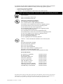 9
9
-
 10
10
-
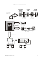 11
11
-
 12
12
-
 13
13
-
 14
14
-
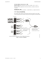 15
15
-
 16
16
-
 17
17
-
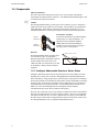 18
18
-
 19
19
-
 20
20
-
 21
21
-
 22
22
-
 23
23
-
 24
24
-
 25
25
-
 26
26
-
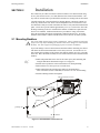 27
27
-
 28
28
-
 29
29
-
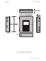 30
30
-
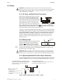 31
31
-
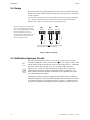 32
32
-
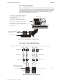 33
33
-
 34
34
-
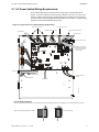 35
35
-
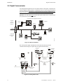 36
36
-
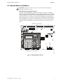 37
37
-
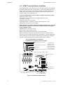 38
38
-
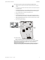 39
39
-
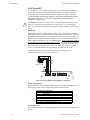 40
40
-
 41
41
-
 42
42
-
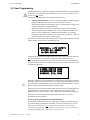 43
43
-
 44
44
-
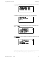 45
45
-
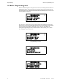 46
46
-
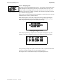 47
47
-
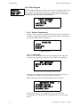 48
48
-
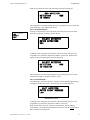 49
49
-
 50
50
-
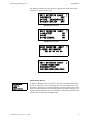 51
51
-
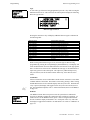 52
52
-
 53
53
-
 54
54
-
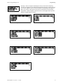 55
55
-
 56
56
-
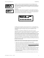 57
57
-
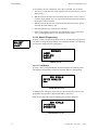 58
58
-
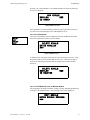 59
59
-
 60
60
-
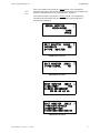 61
61
-
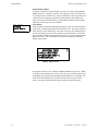 62
62
-
 63
63
-
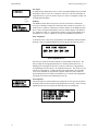 64
64
-
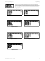 65
65
-
 66
66
-
 67
67
-
 68
68
-
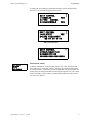 69
69
-
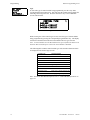 70
70
-
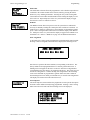 71
71
-
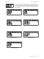 72
72
-
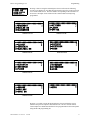 73
73
-
 74
74
-
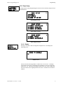 75
75
-
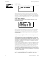 76
76
-
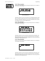 77
77
-
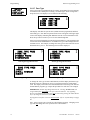 78
78
-
 79
79
-
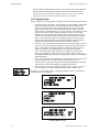 80
80
-
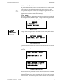 81
81
-
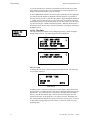 82
82
-
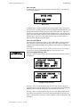 83
83
-
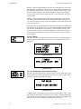 84
84
-
 85
85
-
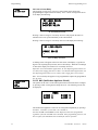 86
86
-
 87
87
-
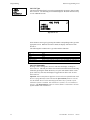 88
88
-
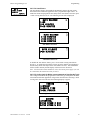 89
89
-
 90
90
-
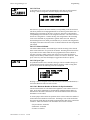 91
91
-
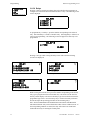 92
92
-
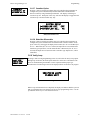 93
93
-
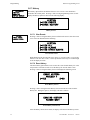 94
94
-
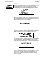 95
95
-
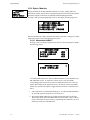 96
96
-
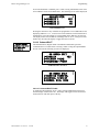 97
97
-
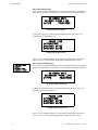 98
98
-
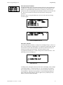 99
99
-
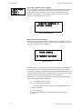 100
100
-
 101
101
-
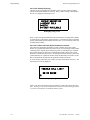 102
102
-
 103
103
-
 104
104
-
 105
105
-
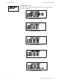 106
106
-
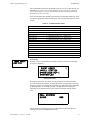 107
107
-
 108
108
-
 109
109
-
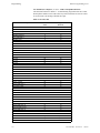 110
110
-
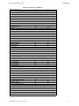 111
111
-
 112
112
-
 113
113
-
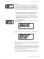 114
114
-
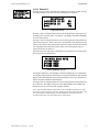 115
115
-
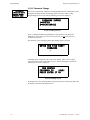 116
116
-
 117
117
-
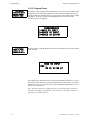 118
118
-
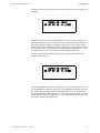 119
119
-
 120
120
-
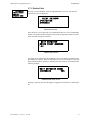 121
121
-
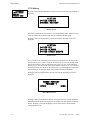 122
122
-
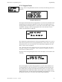 123
123
-
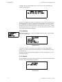 124
124
-
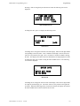 125
125
-
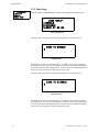 126
126
-
 127
127
-
 128
128
-
 129
129
-
 130
130
-
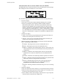 131
131
-
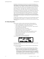 132
132
-
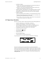 133
133
-
 134
134
-
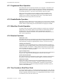 135
135
-
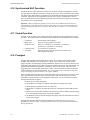 136
136
-
 137
137
-
 138
138
-
 139
139
-
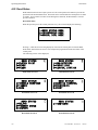 140
140
-
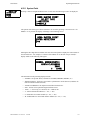 141
141
-
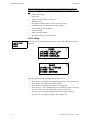 142
142
-
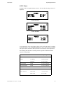 143
143
-
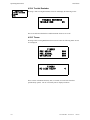 144
144
-
 145
145
-
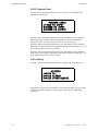 146
146
-
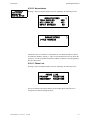 147
147
-
 148
148
-
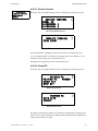 149
149
-
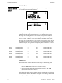 150
150
-
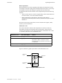 151
151
-
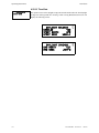 152
152
-
 153
153
-
 154
154
-
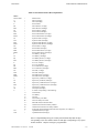 155
155
-
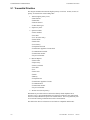 156
156
-
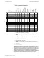 157
157
-
 158
158
-
 159
159
-
 160
160
-
 161
161
-
 162
162
-
 163
163
-
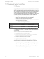 164
164
-
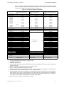 165
165
-
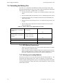 166
166
-
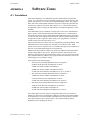 167
167
-
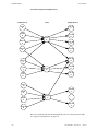 168
168
-
 169
169
-
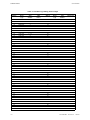 170
170
-
 171
171
-
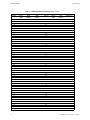 172
172
-
 173
173
-
 174
174
-
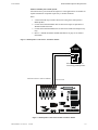 175
175
-
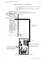 176
176
-
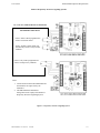 177
177
-
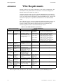 178
178
-
 179
179
-
 180
180
-
 181
181
-
 182
182
-
 183
183
-
 184
184
-
 185
185
-
 186
186
-
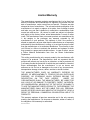 187
187
-
 188
188


Honeywell MS-9200UDLS User manual
- Category
- Fire protection
- Type
- User manual
- This manual is also suitable for
Ask a question and I''ll find the answer in the document
Finding information in a document is now easier with AI
Related papers
-
Honeywell MS-9600UDLSE User manual
-
Honeywell HPF24S6 Installation guide
-
-
-
Fire-Lite Alarms MRP-2001E User manual
-
-
FCI CHG-120 User manual
-
-
-
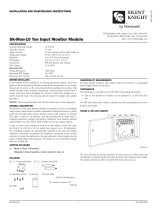 SILENT KNIGHT SK-Mon-10 User manual

Other documents
-
 Fire-Lite MS-9200UDLS User manual
-
Intermatic ET100 SERIES Programming Manual
-
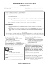 SILENT KNIGHT SK-2-E Fire Alarm Control Panel User manual
-
Viking Smoke Alarm VFR-400 User manual
-
Simplex 4010 Operating instructions
-
Radionics D7024 Operating instructions
-
Aritech 560 Series Installation guide
-
Mircom LT-1040 FX-350 Programming Manual
-
EMS Taktis Control Panel Installation guide
-
Simplex 4005 Operating instructions

