Page is loading ...

COMPREHENSIVE INSTALLER
TECHNICAL GUIDE
For
Models:
EG-1200ATV
EG-1400ATV
EG-1600ATV
Includes Model EG-1800ATV Supplement
EG-1800ATV Supplement Starts On Page 44

The Excalibur Gold Comprehensive Installation Manual
is exclusively provided to Authorized Excalibur Gold retailers.
While every effort has been made to ensure that the information
contained wherein is accurate, Omega Research and Develop-
ment, Inc. can not be held liable or responsible for actions re-
sulting from the use of this information.
C 1998 Omega Research and Development, Inc.
P. O. Box 508
Douglasville, Georgia
30133
(800) 554-4053 (707) 942-9876
Second Edition - Includes EG-1800ATV Supplement Section
October, 1998
Printed in the United States of America
Page 2

TABLE OF CONTENTS
CONTENTSPage 3
Wiring Connections
EG-1200ATV and EG-1400ATV Wiring Diagram ......................................................................................................................................................................... 4
EG-1600ATV Wiring Diagram .................................................................................................................................................................................................... 5
Black Wire Chassis Ground ...................................................................................................................................................................................................... 6-7
Black Wire Antenna Wire (EG-1200ATV and EG-1400ATV) ........................................................................................................................................................ 7-8
Red Wire Constant Power......................................................................................................................................................................................................... 9-10
Yellow Wire Ignition Power ..................................................................................................................................................................................................... 10-11
Orange Wire Grounded Output for Starter Interrupt................................................................................................................................................................ 11-12
Gray Wire Trunk Release Output .............................................................................................................................................................................................. 13
Pink Wire 3rd Channel Output ................................................................................................................................................................................................. 13-14
Green Wire Negative Door Trigger .......................................................................................................................................................................................... 14-15
Blue Wire Negative Instant Trigger .......................................................................................................................................................................................... 16
Violet Wire Positive Door Trigger............................................................................................................................................................................................ 17-18
Brown Wire Negative Siren/Horn Output................................................................................................................................................................................. 18-19
White Wire Positive Flashing Parking Light Output................................................................................................................................................................ 20-21
White/Black Wires Domelight Supervision............................................................................................................................................................................... 21-22
Plug-In Accessories
Valet Switch and Status LED EG-1200ATV and EG-1400ATV ..................................................................................................................................................... 23
Information and Programming Module EG-1600ATV ................................................................................................................................................................. 23
Pager Port All Models ................................................................................................................................................................................................................ 23
Sensor Port All Models .............................................................................................................................................................................................................. 23-24
Backup Battery Port All Models ................................................................................................................................................................................................ 24
Doorlock Operations EG-1200ATV ............................................................................................................................................................................................. 24
Doorlock Operations EG-1400ATV and EG-1600ATV ................................................................................................................................................................... 24
Doorlock Connections All Models ............................................................................................................................................................................................ 25-29
Programming
Programming the Electronic Siren Options............................................................................................................................................................................... 19
Programming Features EG-1200ATV ........................................................................................................................................................................................... 30-32
Programming Transmitters EG-1200ATV .................................................................................................................................................................................... 32-33
Programming Features EG-1400ATV and EG-1600ATV ................................................................................................................................................................ 33-40
Programming Features EG-1400ATV and EG-1600ATV ................................................................................................................................................................ 41
Total System Reset EG-1200ATV ................................................................................................................................................................................................ 42
Personal Coded Override Reset & Total System Reset EG-1400ATV & EG-1600ATV ................................................................................................................. 42-43
Optional Hidden Valet Switch EG-1600ATV ............................................................................................................................................................................... 43

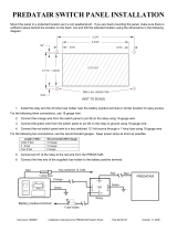
Wiring Diagram Overviews
15 Amp
10 Amp
ORANGE = STARTER-
GRAY = TRUNK
YELLOW = ACC.12V
BLACK = GROUND
RED = +12V
PINK = #3 CHANNEL
GREEN = DOOR-
BLUE = TRIG-
VIOLET = DOOR+
BROWN = HORN/SIREN-
WHITE = LIGHTS+
WHT/BLK = DOME I/O
WHT/BLK = DOME I/O
BACKUP BATTERY
PAGER LED VALET
Red Plug
Blue Plug
Gray: (-) Trunk
Release Output
EG-
1400ATV
Optional
Pager Port
Yellow: Ignition (+) 12 Volts
Black: (-) Ground
Battery+
Red: (+) 12 Volts
Blue: (-) Instant
Violet: (+) Door
(-) Door
Pin Switch
Hood /
Trunk
Switch
Or
Pin
(+) Door
Pin Switch
Pink: (-) 3rd Channel
Output
D/LOCK AUX.1 AUX.2
To (+)
12 volt
To vehicle's wire
To (+) 12 volt or (-) ground
as needed to operate vehicle
circuit
White: (+) Parking Light Output
OPTIONAL SPDT
RELAY FOR
TRUNK RELEASE
Ignition
Switch
White:
To Starter Red: To
Ignition
Switch
Relay
Orange: Armed (-) Output
✄
Brown: (-) Siren Output
Starter
Dual Auxiliary
Sensor
White Ports
Doorlock
Output
Red Port
Plug-In
Valet
Switch
Plug-In LED Status
Indicator
To (+)
12 volt
To (+) or (-)
as needed
OPTIONAL SPDT RELAY
FOR 3rd CHANNEL
To vehicle's circuit
or optional device
AU-SOCKET &
1 SPDT RELAY FOR
STARTER INTERRUPT
White/Black: Dome
Light Output - Connect
To Green Or Violet Wire
Light
Switch
Parking Lights EG-1200ATV & EG-1400ATV WIRING DIAGRAM
Siren
Black
Wire
Siren Red Wire
10 Amp
White/Black:
To (+) Or (-) As Needed
Siren (+) Supply -
Connect to PCB
Flag Terminal or
Short Red Wire
(Early Production)
Siren (+) Supply
(Late Production)
Siren
1.5 Amp
Page 4

EG-1600ATV WIRING DIAGRAM
Yellow: Ignition (+) 12 Volts
Black: (-) Ground
Battery+
Red: (+) 12 Volts
Blue: (-) Instant
Violet: (+) Door
(-) Door
Pin Switch
Hood /
Trunk
Switch
Or
Pin
(+) Door
Pin Switch
Pink: (-) 3rd Channel
Output Green:
(-) Door
D/LOCK AUX.1 AUX.2
AUX.2
15 Amp
10 Amp
ORANGE = STARTER-
GRAY = TRUNK
YELLOW = ACC.12V
BLACK = GROUND
RED = +12V
PINK = #3 CHANNEL
GREEN = DOOR-
BLUE = TRIG-
VIOLET = DOOR+
BROWN = HORN/SIREN-
WHITE = LIGHTS+
WHT/BLK = DOME I/O
WHT/BLK = DOME I/O
BACKUP BATTERY
PAGER ANT. MODULE VALET
Gray: (-) Trunk
Release Output
EG-
1600ATV
Optional
Pager Port
Dual Auxiliary
Sensor
White Ports
Doorlock
Output
Red Port
White: (+) Parking Light Output
Brown: (-) Siren Output
Starter
To (+)
12 volt
To (+) or (-)
as needed
OPTIONAL SPDT RELAY
FOR 3rd CHANNEL
To vehicle's circuit
or optional device
To (+)
12 volt
To (+) 12 volt or (-) ground
as needed to operate vehicle
circuit
OPTIONAL SPDT
RELAY FOR
TRUNK RELEASE
Ignition
Switch
✄
White:
To Starter Red: To
Ignition
Switch
Relay
Orange: Armed (-) Output
AU-SOCKET &
1 SPDT RELAY FOR
STARTER INTERRUPT
White/Black:
To (+) Or (-) As Needed
White/Black: Dome
Light Output - Connect
To Green Or Violet Wire
Light
Switch
Parking Lights Wiring Diagram Overviews
To vehicle's wire
Information and
Programming
Module
Siren
Black
Wire
Siren Red Wire Siren (+) Supply -
Connect to PCB
Flag Terminal or
Short Red Wire
(Early Production)
10 Amp
Siren (+) Supply
(Late Production)
Siren
1.5 Amp
Page 5

Black Chassis Ground WirePage 6
Wiring Connections - 5 Wire Connector
Chassis
Ground
Black Wire
The Black wire's function is to supply chassis ground to the CPU (Central Processing Unit or control module) for the security system's operation. We
recommend that this wire be connected before any of the security system's other wires.
CONNECTION: If you are using an Omega Research and Development Quick Interconnect Harness, ground for the Black wire may be provided from an
existing ground circuit within the vehicle or the Black wire may have a ring terminal already attached. A Quick Interconnect Harness is an adapter wiring harness
which plugs into an existing pair of the vehicle's connectors, with circuits needed for the security system branching off to a connector which plugs into the
system's CPU. The Quick Interconnect Harness allows an incredibly quick, accurate and clean installation. If ground is not provided through the Quick
Interconnect Harness, follow these steps:
Using the correct sized soldered or crimp-on ring terminal, securely connect the Black wire to the metal structure of the vehicle, preferably using an existing
machine-threaded fastener. The battery's negative post is a very poor choice for a grounding point due to the differences in the CPU and vehicle wire and terminal
sizes, and because of the very corrosive environment around the battery. Make sure that the Black wire's ring terminal has contact with bright, clean metal. If
necessary, scrape any paint, rust or grease away from the connection point until the metal is bright and clean. The security system's CPU should be given its
own grounding point (a dedicated ground). Never consider simply splicing the CPU Black wire into an existing "ground" wire, and avoid grounding to sheet
metal unless absolutely necessary.
Grounding The Black Wire To An Existing Bolt.
Security System
CPU
Use an existing machine-threaded
bolt that holds large structural
pieces of the dash frame to the
vehicle's framing structure.
Black Wire
Troubleshooting Tip: If the Black wire has a
poor ground connection, the system can find par-
tial ground through the wires that are connected to
other circuits, but the system will not function cor-
rectly, making you think that you have a defective
CPU. One example of this is when the system is
armed, but the siren sounds with a low volume. The
CPU is trying to ground itself through the siren in-
stead of through its normal Black wire, which
causes the low siren output. The system can par-
tially operate when the Black wire is not properly
grounded, so you would never suspect a poor ground
wire connection. In some cases the security system
could arm and disarm properly -but not function
correctly otherwise.

In some cases, however, grounding to sheet-metal may be the only choice. To
properly use a sheet-metal screw, locate a hidden area where two of the vehicle's sheet
metal panels are overlapped and welded together. After
ensuring that there is adequate depth behind this spot,
drill an appropriate-sized hole. A Drill Bit or a good
quality Self-Tapping Screw may be used. Wrapping a
length of adhesive tape around the Drill Bit will reduce
excessive Drill Bit penetration. At this point, grind
the surface of the metal around the drilled hole, as
the goal is a bright, clean contact area for
the ring terminal. A Carbide Burr Bit or a
Mandrel and Cut-Off Wheel may be used
in a Drill or Die Grinder to accomplish this
quickly. Caution: Use proper eye protection!
Since the screw is being run through two layers of
metal, some thread cutting must occur. A Screw-
gun or Cordless Drill is very handy for this
operation, as the screw may have to be ran
in and reversed several times. Once the
screw can be fully and tightly threaded
into the hole, the star washer and a
ring terminal are put on the screw,
and it is securely tightened. A good
practice to increase the longevity of the
chassis ground connection is apply a
protecting coating of silicone sealant over all of the parts.
Self-Tapping Screw
"Star" Washer
Ring Terminal
Black Wire
Running the screw through two layers
of sheet metal allows more threads to
contact the metal, which reduces the
chances of the screw to strip out or be-
come loose. Grind the surface until
the metal is shiny and clean.
Avoid trying to drill through the
spot welds, which are harder than
the surrounding metal.
Grounding The Black Wire To Sheet Metal.
Black Chassis Ground Wire
Black Antenna Wire
Note: The Black wire attached to the control module is the antenna wire. Do not connect this wire to anything or your transmitter's range will be
reduced or eliminated. Vehicle security systems which are operated by Radio Frequency (RF) must comply with the Federal Communications Commission's
(FCC) Rules part 15, which states that this device must not cause harmful interferences to other electronic devices and that the security system must accept
any interference from other devices, even if this causes undesirable operation of the security system. This means that, at times, an RF-operated security system
Antenna Wire (EG-1200
ATV
& EG-1400
ATV
)
Black Wire
Page 7

Antenna Options For Better Range.
package shelf panel. The antenna wire may also be extended, with the maximum recommended length added to the existing antenna wire being 26 inches (which
may be doubled) of 22 gauge wire. It should be remembered, however, that too much transmitter range can also produce some undesirable operations. Such
a security system is more likely to be accidentally disarmed, especially when the operator is too far away to hear the siren's confirmation chirps. Extreme
operating range will also make the system's receiver more susceptible to extraneous interference. Adequate operating range of 50-100 is acceptable, and it is
normal for the range to be greater in rural areas as compared to urban areas. The fact that range is often very poor in downtown areas, is the result of greater
amounts of RF interference, compounded by the tendency of such signals to be reflected off the tall buildings.
There are several ways to increase the effective
range of the security system's transmitter. The most
basic approach is to remember to route the Black
antenna wire as high in the vehicle as possible,
avoiding metal as much as possible. The metal struc-
ture of the vehicle blocks the transmitter's RF signal,
so if the CPU is mounted deep into the vehicle, such
as in a kick panel, for instance, the transmitter's
operating range will be limited unless the antenna
wire is routed high and away from metal. On many
cars, the "A" pillar interior trim panel overlaps the
windshield. Tucking the antenna wire behind this
trim is an excellent method of obtaining maximum
range. Other options include taping the wire to the
bottom of the dash pad or routing it below the rear
An extended antenna
wire can be routed
around or behind the
dash pad and concealed
behind the "A" pillar
interior trim panel.
The optional AU-ANT ex-
tended range antenna is
shown mounted in two good
locations: blocked from the
driver's view by the rearview
mirror (avoid sunshading)
and beside the "A" pillar trim.
The AU-ANT should be
mounted as high as possible.
may suffer noticeably less transmitter range. In the severest of circumstances, this interference may cause the system to operate erratically, which may include
arming and disarming or going into the panic mode due to the interference. This extreme form of interference, fortunately, is quite rare, as the FCC carefully
regulates the radio frequencies that are assigned to, and transmitting output power of RF devices.
Interference comes from many sources, including some which occur naturally. Any device which is powered by electricity or which has electronic circuitry
can produce electromagnetic or RF interference. Sometimes difficulty is encountered from electrical components and circuits within a vehicle, or by mounting
two receivers too close together. In these instances, shielding the system's CPU to block the interference may
solve the problem. This is easily accomplished by wrapping the CPU in either the flexible metal shielding
designed for automotive audio noise problems or aluminum foil tape and grounding the shield. Care
should be taken to avoid shorting any of the CPU's connectors or terminals and to ensure that as
little of the antenna wire is blocked by the shielding as possible. Grounding the shield is
accomplished by molding the material around one of the mounting "ears" and using a
small bolt and nut to secure a ground wire with two
ring terminals between the CPU and chassis ground.
Black Antenna WirePage 8

Constant Power
Red Wire
The Red wire supplies constant (+) 12 volts for the security system's operation, which includes supplying the built-in relay contacts for flashing the parking
Please note that when (-) ground and (+) 12 volts is first applied to the control module, the system will revert to the state it was last in.
CONNECTION: This connection, like the Ignition Power and Starter Disable, is best made as close to the ignition switch as possible. We urge you to use
an Omega Research and Development Quick Interconnect Harness. A Quick Interconnect Harness is an adapter wiring harness which plugs into an existing
pair of the vehicle's stock connectors, with circuits needed for the security system branching off to a connector which plugs into the security system. If you're
not using a Quick Interconnect Harness, follow the remaining text.
Caution: Be aware of, and avoid, any airbag circuitry. Due to the fact that an installer will not be in a normal, upright seated position, severe injury may occur
in an accidental airbag deployment. Also, use of a volt-ohm meter or multimeter instead of a testlight will greatly reduce the risk of an accidental airbag
deployment. The target wire will have (+) 12 volt positive at all times and in all ignition switch positions. Another location can be at the constant (+) 12 volt
wire behind the fuse block or the fuse/junction block. Never just insert
this wire behind a fuse. The connection location must have
constant (+) 12 volt, 15 amp capacity. Connecting directly
to the battery's positive terminal is not recommended
due to the corrosive environment. Caution: The
Constant (+) 12 volt wire at the ignition
switch may not be fused! Extreme care
must be taken not to short this wire! If
you plan on disconnecting the battery,
always check the car's owner manual
for any cautions or special procedures
involved when disconnecting the vehicle's
battery. The complexity of a modern vehicle's
engine management and body computer systems,
in addition to the presence of air bag systems, may
have an effect on how the battery is disconnected,
how long it is disconnected, how it is reconnected, and what, such as computer learning procedures, should be done after
reconnecting. Also check the vehicle's owner's manual section on fuses. If the Constant (+) 12 volt wire to the ignition switch is fused, the fuse or fuses will
be identified in that section of the owner's manual. Generally, older cars do not have fuses protecting the Constant (+) 12 volt wire(s) to the ignition switch,
but rather, in most cases, a fusible link. Most newer vehicles, however, do have a fuse, usually in the form of a Maxifuse. This fuse, or fuses, are normally
identified as "Ignition Switch" and are usually located in the engine compartment, housed in what may be described in the owner's manual as a "Underhood"
Electrical part of the
Ignition Switch.
Linkage rod connecting
the two parts together.
Mechanical part of the ignition switch,
which is the ignition key cylinder.
Cutaway View Of A Steering Column-Mounted Ignition Switch.
Red Constant Power WirePage 9

or "Engine Compartment" "Fuse Box", "Fuse/Relay Block" or "Electrical Center". Caution: After removing an ignition switch fuse or otherwise turning off
battery voltage to the ignition switch always use your voltmeter to verify that no voltage is present!
Ignition Power
Yellow Wire
The Yellow wire is an ignition input to the security system. With the ignition switch “off”, the Yellow wire has no voltage, and the following can occur:
* The Zone Test feature will operate if the security system is not armed.
* The security system can be armed, either actively by the transmitter or passively by Last Door Arming.
* The Valet Switch will still function if the security system is disarmed.
* The Valet Switch will not disarm the system if it is in an armed or triggered condition.
* If a door is not open, when the ignition switch is turned "off" the security system will unlock the doors if programmed to do so.
* If the system is in Valet mode, when the ignition switch is turned "off", the siren will chirp once as a reminder.
Electrical part of the
Ignition Switch.
Mechanical ignition
key cylinder.
Note: View From Below
Steering Column, With
Lower Trim Panel Removed.
Access to the ignition switch harness on
most cars is obtainable by removing the
underdash "hush panels" and/ or the lower
dash trim panels. On some vehicles, notably
General Motors and Ford/Lincoln/Mercury
products, the electrical part of the ignition switch
is mounted on top of the steering column, near its
base. This switch is connected to the mechanical part
(where the key is inserted) by a linkage rod. Other
vehicles, such as Chrysler, Dodge, Plymouth and
the vast majority of imports, the electrical and
mechanical parts are together, which means that
the ignition switch is high in the steering column,
and that the lower steering column trim may need
to be removed. If soldering this connection, as
recommended, solder quickly with the proper iron
and be aware that a heat sink may be needed to
prevent excess heat in the wire from damaging the
ignition switch.
Combination Ignition Key Cylinder And Ignition Switch.
Red Constant Power Wire
Yellow Ignition Power Wire
Page 10

When the ignition key “on”, the Yellow wire has voltage, and the following can occur:
* Automatic Transmitter Verification will operate when the ignition switch is turned "on".
* The security system cannot become armed, either actively from the transmitter or passively from Last Door Arming.
* The Valet Switch can be used to disarm an armed or triggered security system within 5 seconds of turning the ignition switch "on".
* If the system has a Zone Violation code stored, turning the ignition switch "on" clears the code.
* Remote trunk release will not operate unless a door is open.
* If the parking lights are on for the 30 second period as a result of disarming the system, if the ignition is turned "on" during this time, they will turn off.
CONNECTION: This connection, like the Constant Power and Starter Disable, are best made as close to the ignition switch as possible. If not using a
Quick Interconnect Harness, follow these steps:
At the ignition switch wiring harness, locate the primary ignition circuit. Primary ignition has 0 volts when the ignition key is in the "Lock", "Off" and
"Accessory" positions; and 12 volts in the "Run" and "Start" positions. When the correct wire is located at the ignition switch harness, securely splice the Yellow
wire to it. Not using the primary ignition wire can cause problems with features such as Last Door Arming Doors Lock At Ignition "On", and Unlock At Ignition
"Off".
Yellow Ignition Power Wire
Orange Grounded Output for Starter Interrupt Wire
Grounded Output for Starter Interrupt
Orange Wire
The Orange wire is for a starter disable socket and relay. The function of this wire is to provide a constant 500ma ground output whenever the security
system is armed. This ground output supplies one side of the relay's coil. The other side of the relay coil will be supplied with positive voltage from the
ignition switch, but only if the ignition switch is turned to the "start" position. If this occurs, the coil will energize, triggering the relay, which in turn will open
the starter circuit. The starter interrupt prevents the vehicle from starting only if the security system is armed (including while the security system is
triggered) and will draw current from the vehicle's electrical system only if an attempt is made to start the vehicle.
CONNECTION: This connection, like the Constant Power and Ignition Power circuits, are best done as close to the ignition switch as possible. We urge
you to use an Omega Research and Development Quick Interconnect Harness. A Quick Interconnect Harness is an adapter wiring harness which plugs into
an existing pair of the vehicle's stock connectors, with circuits needed for the system branching off to a connector which plugs into the security system. If
you're not using a Quick Interconnect Harness, follow these steps:
To interrupt the vehicle's starter circuit, the starter wire must be located and cut. We recommend that this be done as close to the ignition switch as
possible. Use a voltmeter, not a test light, to find the correct wire. This wire runs from the ignition switch to the starter solenoid. CAUTION! Avoid the
airbag circuit! Improper use of a test light can cause deployment of the airbag, which may result in bodily injury! Test lights can also damage expensive
onboard computers and associated sensors.
Page 11

Orange Grounded Output for Starter Interrupt WirePage 12
Ignition
Switch
Relay
Starter Disable Socket
White Wire To The Starter
Solenoid Side Of The Cut.
Starter Solenoid
Starter
Motor
Cutting The Vehicle's
Starter Wire Will Leave
Two Sides- The Ignition
Switch Side And The
Starter Solenoid Side.
Starter
Disable
Socket CPU
Orange
Wire
Socket
Orange
Wire
Security
System
Control
Module
Starter Disable Socket Red
Wire To The Ignition
Switch Side Of The Cut.
Wiring A Starter Disable Using A Relay Only.
87a 30
87
85
86
Relay
Starter
Motor
Ignition
Switch
CPU
Orange Wire
Security
System
Control
Unit
C O I L
If Wiring A Relay Without
The AU-SOCKET, Use
The Relay Pin Numbers
On The Bottom Of The
Relay.
Cut The Vehicle's
Starter Wire
Starter
Solenoid
Wiring A Starter Disable Using The AU-SOCKET And One SPDT Relay.
Although a relay can be
wired without using the
starter disable socket, we
recommend using the
socket. Besides being easier
and faster than wiring a re-
lay, the socket includes a di-
ode that prevents the relay
from inductive lockup,
which will prevent the ve-
hicle from being started. If
wiring a relay without the
socket, use this diagram.
The starter wire will read 12 volts only
when ignition key is in "start" position
(cranking the engine). Cut this wire at a suit-
able location. Confirm that this is the cor-
rect wire by turning the ignition switch to
the "start" position. The starter should not
engage. Now that the starter wire has been
cut, there are two sides - the ignition switch
side and the starter solenoid side. Connect
the starter disable socket's Red wire to the
ignition switch side, and its White wire to
the starter solenoid side. Be sure that you
make good, solid electrical connections as
this is a high amperage circuit. Connect the
security system's Orange wire to the Or-
ange wire of the starter disable socket.
Note: If the Orange wire touches 12
volts positive directly or has more than
a 500ma ground load, the control mod-
ule will be damaged.

The function of the Pink wire is to provide an optional output similar to the Gray trunk release wire. Pressing the proper transmitter button for three seconds
activates this output. Once activated, this output will last for one second, or, for as long as transmitter button is held down, with a maximum of 15 seconds.
This function can be used to activate other optional modules (Example: car starting equipment or power window roll up units). For most applications an optional
relay will be needed (use the diagram on the following page or the above diagram for the Gray wire). This output will not disarm the security system when
activated. For the EG-1200ATV, EG-1400ATV and EG-1600ATV, the small lower transmitter button is used to activate this output.
Unless the vehicle's trunk
release switch negatively
triggers a release relay
which draws no more than
250ma, an optional relay
must be used. Connect the
Gray wire to relay pin (86),
and connect constant 12 volt
positive to relay pin (85).
Connect pins 87, 87a & 30
as indicated in this typical
diagram:
To 12 Volt
Positive
86
85
87a
87
C O I L
30
To Positive Or Negative As Needed. In This Case,
Negative Is Required. In Others, Positive. In Some
Applications The Wire Will Rest At Ground. Cut
The Wire, Switch Side To Pin 87a, Solenoid Side
To Pin 30.
Release
Solenoid
Relay
Gray Wire
Release
Switch
To 12 Volt
Positive
Wiring An Optional Relay For Trunk Release.
Security
System
Control
Module
3rd Channel Output
Pink Wire
Wiring Connections - 8 Wire Connector
Trunk Release Output
Gray Wire
The function of the Gray wire is to provide an optional output, the primary use being trunk release. For model EG-1200ATV, EG-1400ATV and EG-1600ATV
press and hold the transmitter's small center button for three seconds to activate this output. When activated the Gray wire will provide a 250ma ground pulse
for 1 second; or, stay grounded for as long as you depress the transmitter button(s), for up to 15 seconds. Also, the security system can be programmed to
automatically disarm, chirp the siren twice, unlock the doors and turn the lights on for 30 seconds. The remote trunk release feature can be operated anytime
with the ignition switch is "off", or it may also be operated while ignition switch is "on", provided that a door is open at the same time the transmitter's small
center button is pressed. This prevents the trunk or rear hatch from being opened from the transmitter while driving. Whenever this output is used, the siren
will chirp twice.
Gray Trunk Release Output Wire
Pink 3rd Channel Output Wire
Page 13

Gray and Pink Wires Continued
Green Negative Door Trigger Wire
Page 14
The Green wire's function is an open door input to the control module for vehicles having negative switching door pin switches. An open or closing door
will affect the following operations:
A) When the security system is armed, opening a door will trigger the security system; causing the siren or horn to sound, the exterior lights to flash, and
the doors to relock.
B) If the Last Door Arming feature is utilized, after turning "off" the ignition switch and closing the door, the Last Door Arming sequence will begin. Upon
closing the last door, this is indicated by a siren chirp or horn honk, one parking light flash and a fast flashing LED Status Light. Thirty seconds after
the last door closes, the siren will chirp again (or the horn will honk again) and the parking lights will flash once again, indicating that the system is armed.
C) Opening a door while the exterior lights are on after disarming the security system will cause the exterior lights to turn off 10 seconds after the opening
of the door. If the Last Door Arming feature is utilized, closing the door will initiate Last Door Arming.
D) If the Doors Lock With Ignition "On", and Unlock With Ignition "Off" features are turned on along with the Open Door Bypass feature, if a door is open
when the ignition switch is turned "on" with a door opened, the doors will not automatically lock; if a door is open when the ignition switch is turned
"off", the doors will not automatically unlock.
E) Opening a door during the 90 second Automatic Rearming cycle, or the 30 second Last Door Arming cycle will suspend that automatic function for as
long as the door is open. When the door is closed, the Last Door Arming sequence will restart.
F) If this wire is grounded at the time the security system becomes armed from the transmitter, the circuit bypass feature will leave the Green wire circuit
unprotected until the circuit becomes ungrounded.
G) If the system is triggered by the Green wire, on all models the LED Status Light will flash 3 times and pause until the ignition switch is turned “on”. The
EG-1600ATV will additionally display "d" on the Information and Programming Module's digital display. The system does not have to reset itself for this
feature to operate.
Configuring An Optional Relay
For Trunk Release Or 3rd
Channel Output.
To (+)
12 volt.
To (+) 12 volt or (-)
ground as needed to
operate vehicle circuit.
To Control Unit
Pink Wire
30
85 86
87a
87 To (+)
12 volt.
To (+) 12 volt or (-)
ground as needed to
operate vehicle circuit.
To Control Unit
Gray Wire.
30
85 86
87a
87
Negative Door Trigger Wire
Green Wire
To vehicle's trunk
release circuit.
To vehicle's circuit or
optional device.

H) When the ignition switch is "off", if the Green wire becomes grounded, the LED Status Light will flash 3 times and pause for as long as the door is open.
This is the Zone Testing feature, which allows the installer or vehicle owner to visually see trigger circuits which are in a violated state.
CONNECTION: Connect the Green wire to a wire in the vehicle which is common to all the door pin switches. The correct wire in this type of dome light/
door jamb pin switch system will have no voltage present and will also show chassis ground when the doors are opened, and up to 12 volts when the doors are
closed. The 12 volts present on the wire with the doors shut is simply voltage that the meter detects through the dome light bulb filament(s). When the door
is opened, a path to ground is presented to this voltage (known as ground potential), which causes the voltage to flow to ground (this is referred to as electrical
current). The completion of this circuit, caused by opening the door, resulting in current flow, causes the dome light bulb's filament to glow because of the
filament's resistance to the electrical current.
The correct wire will show this change when any of the doors are opened. If the vehicle has delay dome lights, remember to take this into account when
testing the wire. If the car has a delay dome light the Circuit Bypass feature will allow the system to be armed from the transmitter instantly and will start
protecting the Green wire circuit when the dome light turns off. In Last Door Arming mode, the system arms 30 seconds after the delay dome light turns off.
The following diagram illustrates a basic negative courtesy light system:
Passenger
Pin
Switch
To 12 Volt
Constant
Driver
Pin
Switch
Note: The Driver Pin Switch Often Will Have
An Extra Wire That Goes To The Ignition Key
Warning Chime. This Circuit Will Trigger The
Security System, But Only From The Driver's
Door, And Is The Incorrect Trigger Wire.
This Is The Correct Trigger
Wire. Connection May Be
Made At Any Point.
Dome
Light
Typical Grounding-Type Dome Light System.
If the pin switch is mounted in the metal structure of the vehicle, and
the dome light goes out when the switch is removed, suspect a grounding-
type dome light system. If the switch is mounted in plastic, a constant
ground wire will also be present. While the traditional pin switch is
mounted in the front door jamb area, also be aware that many vehicles
utilize other types of switch devices to operate the interior lights. Some
imports have a sliding type of switch and many imports have the pin or
sliding switches in the rear door jamb area. In addition, some vehicles
utilize switches in the doors, either connected to the exterior door handles
or to the latching mechanism. A car that features the dome lights
illuminating when the exterior door handle is lifted is an example of this
type of switching system.
Also be aware of vehicles which diode-
isolate each door. Typically, this is usually en
countered with dash displays that indicate indi-
vidual doors being ajar. The proper wire to
connect to in this type of system is the common
wire which is routed to the dome light itself.
Green Negative Door Trigger WirePage 15

Blue Negative Instant Trigger WirePage 16
The Blue wire is a Negative instant trigger used primarily to detect entry into the hood or trunk area of a vehicle. Complete functions are:
A) When the security system is armed, grounding the Blue wire will trigger the system, causing the siren to sound, the exterior lights to flash, and the doors
to relock.
B) If the Blue wire is grounded when the system is armed, the Circuit Bypass feature will leave the Blue wire circuit unprotected until it becomes ungrounded.
C) If the Blue wire becomes grounded during the 90 second Automatic Rearming cycle, or the 30 second Last Door Arming cycle, that automatic function
will be suspended for as long as the door is open. When the door is closed, Last Door Arming will start.
D) When the Last Door Arming feature is utilized, if the Blue wire is grounded when the last door is closed, the Last Door Arming process will not start
until the Blue wire is ungrounded.
E) If the security system is triggered by the Blue wire, the LED Status Light will flash 2 times and pause until the ignition switch is turned “on”. The
EG-1600ATV will additionally display "H" on the Information and Programming Module's digital display. The system does not have to reset itself for
this feature to operate.
F) When the ignition switch is "off", if the Blue wire becomes grounded, the LED Status Light will flash 2 times and pause for as long as the Blue wire is
grounded. This is the Zone Testing feature, which allows the installer or vehicle owner to visually see trigger circuits which are in a violated state.
CONNECTION: The included pin switches may be installed to provide this trigger circuit Or, if there are existing switches (example: a light in the luggage
compartment or a "Trunk Ajar" light in the dash), the Blue wire may be connected directly, provided this is a negative ground switching circuit. An indication
of such a circuit is the wire having no voltage present when the hood or trunk is open, and up to 12 volts when the hood or trunk is closed. This circuit cannot
be used with mercury switch types of hood or trunk lights. If the vehicle is equipped with a usable trunk or hood circuit, locate the proper wire and splice
Blue wire direct.
Negative Instant Trigger
Blue Wire
Optional
Electronic
Sensor
Blue (-) Instant Trigger Wire.
Security
System
Control
Module
When wiring more than one of the
vehicle's circuits and/or additional circuits
to this wire, diode-isolation of the circuits
may be required. An example would be
wiring a hood pin switch and trunk light
switch together. Without isolating, the trunk
light will turn "on" whenever the hood is
raised. Also, diode-isolation is necessary
when combining electronic sensors together
or in the same circuit with pin switches.
Diode-Isolating Multiple Negative Instant Triggers.
Trunk
Light Trunk
Pin
Switch
Hood
Pin
Switch
Note: Use IN4002 Diodes,
Which May Be Found At
Most Electronics Stores.

Positive Door Trigger Wire
Violet Wire
The Violet wire's function is an open door input to the control module for vehicles having positive 12 volt door pin switches. An open or closed door will
affect the following operations:
A) When the security system is armed, opening a door will trigger the security system; causing the siren or horn to sound, the exterior lights to flash, and
the doors to relock.
B) If the Last Door Arming feature is utilized, after turning "off" the ignition switch and closing the door, the Last Door Arming sequence will begin. Upon
closing the last door, this is indicated by a siren chirp or horn honk, one parking light flash and a fast flashing LED Status Light. Thirty seconds after
the last door closes, the siren will chirp again (or the horn will honk again) and the parking lights will flash once again, indicating that the system is armed.
C) Opening a door while the exterior lights are on after disarming the security system will cause the exterior lights to turn off 10 seconds after the opening
of the door. If the Last Door Arming feature is utilized, closing the door will initiate Last Door Arming.
D) If the Doors Lock With Ignition "On", and Unlock With Ignition "Off" features are turned on along with the Open Door Bypass feature, if a door is open
when the ignition switch is turned "on" with a door opened, the doors will not automatically lock; if a door is open when the ignition switch is turned
"off", the doors will not automatically unlock.
E) Opening a door during the 90 second Automatic Rearming cycle, or the 30 second Last Door Arming cycle will suspend that automatic function for as
long as the door is open. When the door is closed, the Last Door Arming sequence will restart.
F) If this wire is grounded at the time the security system becomes armed from the transmitter, the circuit bypass feature will leave the Green wire circuit
unprotected until the circuit becomes ungrounded.
G) If the system is triggered by the Violet wire, on all models the LED Status Light will flash 3 times and pause until the ignition switch is turned “on”. The
EG-1600ATV will additionally display "d" on the Information and Programming Module's digital display. The system does not have to reset itself for this
feature to operate.
CONNECTION: Connect the Violet wire to a wire in the vehicle which is
common to all the door pin switches. The correct wire for this type of dome
light/door jamb pin switch system will have 12 volts present when the doors
are opened, and chassis ground when the doors are closed. The correct wire
will show this change when any of the doors are opened. If the car has a
delay dome light the Circuit Bypass feature will allow the
system to be armed from the transmitter instantly
and will start protecting the Violet wire circuit
when the dome light turns off. In Last Door
Arming mode, the system arms 30 seconds
after the dome light turns off. This
diagram illustrates a basic positive
courtesy light system:
Passenger
Pin
Switch
Driver
Pin
Switch
This Is
The Correct
Trigger Wire.
To
Chassis
Ground
To Constant
(+) 12 Volt
Typical Positive Dome Light System.
Violet Positive Door Trigger Wire
Dome
Light
Page 17
Please see the note on the
following Page concerning this wire.

Violet Positive Door Trigger Wire Continued
Brown Negative Siren/Horn Output Wire
Page 18
Note: The Driver Pin Switch Often Will Have An Extra Wire That Goes To The Ignition Key Warning Chime. This Circuit Will Trigger The Security System,
But Only From The Driver's Door, And Is The Incorrect Trigger Wire. Please note that Positive Courtesy Light Pin Switches Will Have One Wire Which Will
Remain (+) 12 Volts At All Times. At Least One Other Wire Will Have (+) 12 Volts When A Door Is Open, And No Voltage When All The Doors Are Closed.
This Type Of Switch Will Operate The Dome Light Even If Removed From The Chassis Of The Vehicle.
Negative Siren/Horn Output
Brown Wire
The Brown wire is a 1 Amp Negative output to operate the system's audible functions. This output is programmable, and may used to sound an electronic
siren (program "steady", the factory setting) or the vehicle's existing horn (program "pulsed"). Instead of the siren, if the vehicle's horn is preferred, this
output must be changed from steady to pulsed, allowing the use of the horn for the alarm's audible responses. If the vehicle does not utilize an existing horn
relay, one must be added or the output's 1 Amp capacity may be exceeded, which will damage the control module. The electronic siren requires a continuous,
steady output. The siren features six different siren tones, which change every 5 seconds. When configured for use with a horn, this output pulses for 10
seconds, then pauses for 5 seconds, repeating this cycle for the duration of the activated alarm period. This prevents the horn from overheating, thereby
ensuring a maximum useful horn life to the vehicle owner. When this output is programmed for pulsed horn operation, an additional programmable feature
allows loud or soft confirmation honks.
CONNECTION: If used with the electronic siren, the Brown wire may be connected directly to the siren's Black wire, and the siren's Red wire is
connected to the Siren Positive Terminal on the system's control module. If used to sound the horn, the Brown wire may be connected directly to the vehicle's
existing horn switch wire, which is typically found at the steering column. The correct wire will show Positive 12 Volts normally, and no voltage when the
horn is honked. Direct connection of the Brown wire is to an existing horn switch-to-relay wire only. Once the vehicle's horn wire is identified, probe the
wire with a standard test light connected to Negative chassis ground. If the horn honks when probed, a direct connection may be made. If not, use the
following diagram to configure an optional relay. CAUTION! This is one of the few uses left for a standard test light in a modern vehicle! Use a digital
multimeter (DMM) to identify the horn wire first. Probing an Airbag circuit with a standard test light can cause the Airbag to deploy!
AU-72 Electronic Siren: The AU-72 Electronic Siren has a 127 dB (decibel) sound level and features six
police siren sounds which change every 5 seconds to produce twelve sounds per minute. These sounds may be
programmed (described below) to customize the audible output of the alarm. The AU-72 also features softer
confirmation chirps, which may be changed to full volume by cutting the Black loop wire on the siren. This
siren's sound output is 127 decibels (dB) and rated at 12 Volts, 2 amps. The AU-72 measures 3 7/8" round and
4 1/8" deep and has twin 12' wiring leads

One alternative is to disconnect the horns, then operate the horn switch. A clicking sound from the vehicle will confirm the presence of a horn relay.
Another alternative is to check a wiring schematic of the vehicle in question.
Brown Negative Siren/Horn Output WirePage 19
MOUNTING THE SIREN: Find a location in the engine compartment away from the extreme heat of the engine and manifold. A suitable location will
offer a firm mounting surface, will also allow sound dispersion out of the engine compartment, and not be accessible to a thief. The siren must be pointed
downward to avoid moisture collecting inside it and to enhance sound dispersal. The Brown Siren/Horn output wire has a 1 Amp capacity, which, if
exceeded, can damage the security system control module. Certain situations, among them multiple optional sirens or a vehicle which lacks a horn relay, an
optional SPDT relay is required.
OEM Horn
Wire
OR
Siren
Siren
Black
Wire
Siren Red:
To (+) Terminal
Typical Connections
30
86 87a 85
87
To vehicle's
horn wire.
(+) or (-) as needed
to operate the horn /
sirens
(+) 12 Volts
Brown wire
from module
Configuring A Relay, When Required
Security
System
Control
Module
Brown: (-) Horn Or
Optional Siren Output
Siren (+) Supply Short Red Wire
(Early Production)
Siren (+) Supply -PCB Flag
Terminal (Late Production)
PROGRAMMING THE ELECTRONIC SIREN OPTIONS- The electronic siren has features which will allow customized options:
1) For louder Confirmation Chirps, cut the Black loop wire on the siren. This loop wire may be wired to a single pole, single throw switch mounted accessible
to the driver, which will allow the softer/louder confirmation chirps as the driver desires.
2) To eliminate the chirps completely, cut and remove resistor R11 on the siren's Printed Circuit Board (PCB). See Programmable Siren Tones below for siren
disassembly and reassembly (R11 is located on the top corner of the PCB).
3) To temporarily eliminate the Confirmation Chirps from the transmitter, press and release the small transmitter button before you press and release the large
arm/disarm button. The Confirmation Chirps will be eliminated for that arm or disarm operation only.
4) Programmable Siren Tones (must have "M3760-3" IC; early production units' tones are non-programmable):
a) Gain access to the top of the siren's Printed Circuit Board (PCB) by removing the two outer, exposed screws inside the siren bell. Pull out the grommet
where the harness enters the bell and remove the magnet/PCB assembly.
b) Access the back of the PCB by removing the single phillips screw in the center (do not lose the Black plastic spacer between the PCB and the magnet).
c) Turn the back of the PCB so that the board number is viewed properly. Directly below the PCB board number are six vertical printed tracks. These tracks
are in order, left to right, starting with the first siren sound heard to the sixth. Cutting a track will eliminate the like-numbered sound.
d) Carefully reassemble the siren in reverse order of disassembly, making sure that the plastic PCB spacer and bell wiring grommet are reinstalled.

White Positive Flashing Parking Light Output WirePage 20
Positive Flashing Parking Light Output
White Wire
The White wire is a positive 12 volts 7 amp output for exterior flashing light confirmation and to attract attention to the vehicle if the security system is
triggered. Also, upon disarming, this circuit will stay on for 30 seconds to confirm disarming and to illuminate the way to the vehicle, which gives added security
when approaching the vehicle at night.
CONNECTION: Connect the White wire directly to the vehicle's positive 12 volts parking light circuit. This wire can usually be found at the following
locations: at the Headlight Switch, at the Fuse/Junction Block, or in the rear body wiring harness which is usually found in the driver's kick panel. The correct
wire will show positive 12 volts when the headlight switch is in the "Parking Light" and "Head Light" positions. When such a wire is located, be sure to also
test that it is non-rheostated: while metering the wire, operate the dash light dimmer control. The correct wire will show no change in voltage when the dimmer
is operated. Caution: Do not attempt to flash the parking lights by connecting the White wire to a rheostated (dimmer) circuit! This will backfeed the parking
lights through the rheostat or illumination control module, and possibly cause damage to the vehicle or system control unit. Also, if the White wire touches
chassis ground without the protection of the 10 amp fuse, the Printed Circuit Board and onboard relay will be damaged. Some vehicles, notably Toyotas, have
a parking light relay which is triggered by a negative ground circuit from the headlight switch. These cars can still be connected directly to the White wire by
finding the parking light circuit after the relay, usually at the Fuse/Junction Block.
Connecting The White Wire Directly To Standard Parking Lights.
Security
System
Control
Module
3 Suggested Connections
Rear Body Harness
Junction
Block
Head
Light
Switch
Dim-
mer
10 Amp
Caution:
Do not
connect to
the dimmer circuit!
Damage to the control
unit or vehicle can
occur!
White
Wire
Dash Lights
It is not recommended to flash the
headlights instead of parking lights. The
halogen headlights found in modern ve-
hicles are not designed to be rapidly
turned on and off. If connected to the
security system, a reduction of their
useful life may be noticed. If flashing
the headlights is still desired, a relay
must be used, since the headlight's cur-
rent draw exceeds the 7 amp rating of
the onboard relay. If flashing headlights
and parking lights are desired, use the
diagram for left and right parking lights
using two relays - one relay will supply
the parking lights and the other relay
will supply the headlights. Any appli-
cation that requires more than 7 amps
of output must use an external relay.
/