MEGATRONIX KP20 Installation And Wiring Instructions
- Category
- Motorcycle Accessories
- Type
- Installation And Wiring Instructions

MEGATRONIX
KP20 – PROGRAMMABLE ILLUMINATED DIGITAL KEYPAD IMMOBILIZER
INSTALLATION AND WIRING INSTRUCTIONS
WARNING: NOT RECOMMENDED TO USE THIS
SYSTEM TO INTERRUPT IGNITION OR FUEL PUMP.
1. Connect all the wires per wiring diagram:
a. RED Wire – System Power, Positive (+):
Connect to a constant positive 12 or 24 volt
battery source (Fused connection recommended).
b. BLACK Wire – System Ground, Negative (–):
Connect to a clean, solid, unpainted section of the
vehicle frame. Do not connect this wire to any
existing ground wires supplied by the factory wire
loom. Make connection to vehicle's frame directly.
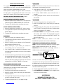
c. BROWN Wire – Horn Honk Output, Negative (–)
(OPTIONAL FEATURE):
The vehicle’s horn can be used as a warning
audible device. It is a transistorized low current
output (–200mA). Connect to the low current
ground (negative) output from the vehicle's horn
switch. Adding a relay as below is recommended.
NEGATIVE SWITCHED HORN
(+) BATTERY
SOURCE (–) VEHICLE HORN
86
SWITCH OUTPUT
(–) BROWN WIRE
HORN OUTPUT (–) GROUND SOURCE
85 87
30
If the vehicle uses a positive (+) horn switch, a
20/30Amp SPDT automotive relay is required to
convert the brown wire to positive. Connect relay
terminal 86 to the brown wire. Connect relay
terminal 87 to the low current positive (+) horn
switch output. Connect relay terminals 85 and 30
to a fused positive (+) battery source.
POSITIVE SWITCHED HORN
(+) BATTERY
SOURCE (+) VEHICLE HORN
86
SWITCH OUTPUT
(–) BROWN WIRE
HORN OUTPUT (+) BATTERY SOURCE
85 87
30
d. ORANGE Wire – Starter Disable Output,
Negative (–):
This wire is provided to control the starter disable
relay. It gives a constant ground (negative) output
while the system is armed (–200mA). Connect this
wire to terminal 86 of the starter disable relay.
e. YELLOW Wire – Ignition Switched Input,
Positive (+):
This wire receives positive (+) when the ignition
switch is in the "ON" and "START" positions and
receives "0" volts when the ignition switch is in the
"OFF" position. Connect this wire to the positive
(+) ignition crank source wire as well as terminal
85 of the starter disable relay.
f. Starter Disable Wiring:
Find the starter solenoid wire (usually located on
starter) that goes to the ignition switch.
Using a voltmeter, connect one probe of the
voltmeter to ground and connect the other end of
the probe to the starter wire, it should receive
positive (+) only when the ignition key is in the
START (CRANK) position.
Cut the starter wire and try to start vehicle. The
engine should not crank over.
If the wires need to be extended, they must be the
same gauge as the cut starter wire.
Connect key switch wire to terminal 30 and starter
wire to relay terminal 87a of the disable relay.
2. Mount the keypad on the dashboard close to the
operating area with either double sided tape or the
bracket and screws provided.
3. Hide the relay and socket where intruders cannot
easily locate them.
4. After installing, enter the default code to test the unit
for functionality.
5. Asterisk (*) LED is blue and indicates system status.
All other LEDs are red including number sign (#).

OPERATING INSTRUCTIONS
The system is designed to activate and deactivate
immobilization via a relay. It can be armed and disarmed
simply by keying a programmable security code.
While system is armed, if the ignition switch is turned to
the ON position, the keypad lights will flash and horn will
sound for 15 seconds (If horn honk output is connected).
FACTORY DEFAULT DISARMING CODE: 123456
PASSIVE ARMING (AUTOMATIC ARMING)
1. When the ignition key is turned to OFF, the system will
automatically enter ARMED MODE after 30 seconds.
2. The blue LED will blink slowly to indicate the status.
ACTIVE ARMING (USER ARMING)
1. When the ignition key is turned to OFF, press * then #.
2. The keypad will chirp two times and system will enter
ARMED MODE.
3. The blue LED will blink slowly to indicate the status.
DISARMING
1. Press * then enter your code then press #.
2. The keypad will chirp two times to indicate the correct
code was entered.
3. Within 15 seconds, turn the ignition to ON. System will
disarm and blue LED will turn off.
4. Before pressing #, if you realize you entered an
incorrect digit, press * to re-enter the code.
5. If an incorrect code is entered, the keypad will chirp
four times and will sound the horn once (If horn output
is connected).
6. If incorrect codes are entered three times consecutively,
the keypad lights will flash and the horn will sound for
15 seconds (If horn honk output is connected). The
blue LED will flash rapidly two times then turn off and
system will be in LOCKOUT MODE for 3 minutes.
PROGRAMMING DISARMING CODE
The keypad can be programmed with a custom disarm pin
code that can be changed to increase security level.
To change disarm pin code:
1. Disarm the keypad and leave the ignition ON.
2. Within 15 seconds, press * then enter your new custom
code then press #.
3. The keypad will chirp two times meaning the new code
has been confirmed and stored.
4. The disarm code can be 4, 5, or 6 digits in length.
PANIC MODE
NOTE: This feature will only sound the horn if the horn
honk output is connected to the vehicle.
1. While ignition is ON or OFF, if the user senses they are
in danger, they can activate PANIC MODE.
2. To activate PANIC MODE, press and hold # for 3
seconds.
3. The keypad lights will flash and the horn will sound for
15 seconds.
VALET MODE
1. Disarm the keypad and turn the ignition to OFF.
2. Within 30 seconds, press * then enter your code then
press #.
3. The keypad will chirp three times and system will enter
VALET MODE. The blue LED will stay on solid whether
ignition is in the ON or OFF position.
4. Exit VALET MODE: Turn the ignition to ON, and within
30 seconds, press * then #. The keypad will chirp three
times, indicating system has exited VALET MODE. The
Blue LED will turn off.
NOTE: In VALET MODE, the vehicle is not under
immobilization protection and can be started freely.
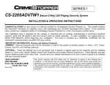
EMERGENCY OVERRIDE (OPTIONAL FEATURE)
NOTE: If you do not want this feature, do no wire a toggle
switch (Should be rated 3A 250V AC / 6A 125V AC).
IMPORTANT: Place the SPST on/off toggle switch in a
hidden location so an intruder cannot access it.
87a
85
3
0
86
O
range wire keypad
“Start”
“On”
White wire
X
Cut
Red wire
Orange wire
“Acc”
“Off”
Starter
Yellow wire to
Ignition Switch
Yellow wire keypad
Connect one wire of an optional toggle switch to the
orange wire from the keypad. Connect the other wire from
the toggle switch to terminal 86 of the starter disable relay.
If keypad has failed or customer has forgotten their code
and cannot disarm the system:
1. Flip the toggle switch to OFF to override the system.
2. Exit EMERGENCY OVERRIDE: Flip the toggle switch
to ON to exit override mode.
MEGATRONIX
WWW.MEGATRONIXUSA.COM
COPYRIGHT © MEGATRONIX, CA U.S.A.
-
 1
1
-
 2
2


MEGATRONIX KP20 Installation And Wiring Instructions
- Category
- Motorcycle Accessories
- Type
- Installation And Wiring Instructions
Ask a question and I''ll find the answer in the document
Finding information in a document is now easier with AI
Other documents
-
Directed Electronics 560XV Installation guide
-
-
Directed Electronics Hornet 564T User manual
-
Viper 881 XP Installation guide
-
-
Directed Electronics Python 990 User manual
-
-
-
Omega EG-1400ATV Installation guide
-
 Crimestopper Security Products CS-2205 User manual
