Page is loading ...

08/07 MI-K9-Classic-EDP
BACK COVER
PRINTER’S NOTE:
production back cover
is to be printed with gray
scale front cover; this is a
place marker cover.
K-9
K9-Classic-EDP
INSTALLATION
INSTRUCTIONS
COPYRIGHT 2007: OMEGA RESEARCH & DEVELOPMENT, INC.
FRONT COVER
PRINTER’S NOTE:
production front cover
is gray scale; this is a
place marker cover.

Page - 35
Wiring Diagram Overview ........................................................................... 18-19
Installation Considerations ........................................................................... 3-5
Status Light & Valet Switch
Wiring Connections
Main Wiring Harness ................................................................................... 6-8
Secondary Wiring Harness ........................................................................... 9-15
Smart Trigger
Accessory Connections
DLS Power Doorlock Port...............................................................16-17 & 20-21
Backup Battery Port ..................................................................................... 21
Sensor Port ................................................................................................... 21-22
Data Port....................................................................................................... 22
Factory Alarm Arm/Disarm, Options Port ................................................... 22
Programming
The Programmable Features ......................................................................... 23-31
Programming Features.................................................................................. 32
Programmable Features Matrix .................................................................... 33
Contents
Omega Disclaims Any Responsibility or Liability In Connection With Installation.
The K9-Classic-EDP’s transmitters are pre-programmed at the factory to
operate the system. If adding or replacing transmitters or controllers, please
see the Operation Guide booklet for Transmitter programming.
Copyright 2007 Omega Research and Development, Inc.

Page - 34 Page - 3
Installation Considerations
Before Starting The Installation: This entire booklet should be read
before starting the installation. An understanding of which control module wires
are to be used and their functions is essential. Installations will vary from car to car
, as some control module wire connections are required, while others are optional.
Before starting the installation, it should be determined which control module
wires will be used. Most installers will list these wires, then "map out" the instal-
lation by locating and noting the target wires in the vehicle. This will also deter-
mine the best location for the control module, which is mounted upon completion
of the installation and testing of the system.
Some of the wiring connections, such as power, ignition and starter interrupt, are
best made at the ignition switch harness, located around the steering column area.
Please carefully read these instructions before
starting the installation of the K9-Classic-EDP
security system. The numerous wiring
connections required, and the options offered
by several of the programmable features makes
pre-planning the installation critical.
- IMPORTANT -
More complete instructions for programming
transmitters and features may be found in the
Operation Guide manual.
Other typical connection points may be behind the dash or in the kick panel areas,
for parking and/or interior lights, trigger circuits and power doorlocks. Soldering
or proper use of crimping terminals for all wiring connections are recommended.
CAUTION! Avoid the Airbag circuit!
Especially avoid any harness
or wires encased in Yellow or Red tubing or sleeves. Do not use
a standard test light, as it can deploy an airbag or damage on-
board computers and sensors if the wrong circuits are probed. A
Digital Multimeter (DMM) should be used.

Mounting The Control Module: The Control Module contains the
necessary electronics required for the system's operation. Always mount this mod-
ule in the vehicle's interior compartment, in a secure location that is not easily
accessible. Ensure that moisture, vibration and temperature extremes are mini-
mized. Acceptable locations include mounting behind the dash, behind the glovebox
or other interior panels.
Mounting The Electronic Siren: The electronic “2-n-1 Psycho Siren”
must be mounted external to the vehicle but not accessible or vulnerable to tam-
pering. Locations in the engine compartment typically offer the best mounting
opportunities. See page 9 for specific mounting and connection details.
Page - 4
Power Doorlock Options: The K9-Classic-EDP has the flexibility of
these options for interfacing a vehicle’s power doorlocks.
DLS Port- This option is the traditional “DLS” port, which can direct-wire
basic 3-wire Negative pulse doorlocking systems, and accept all Omega analog
doorlocking accessories (dual, triple relay sockets, or the modular clip-on add-on
relay packs). All Omega doorlocking data bus module accessories can be driven by
either this port, and the DLS port offers two unlocking outputs, so that driver’s door
priority unlocking can be configured. See pages 16-21 for basic wiring diagrams.
Data Port for IntelliKit Modules & Bypasses: Omega IntelliKit data bus
interface modules and bypass kits simply plug into this port. These data-to-data
(D2D) accessory products save time, and in many cases offer the only acceptable
interface means for many newer vehicle’s doorlocking system and/or for the OEM-
antitheft bypass when adding an alarm or an optional accessory remote start module
Status Light and Valet Switch: The Status Light may be custom-mounted
inside the vehicle by drilling a 9 / 32” hole in a suitable interior panel; be sure to
carefully ensure that the area behind the location has an unobstructed depth of at
least 1/2”. Then route the wiring harness through the hole to the control module,
and snap the light in place. Mount the valet switch, using its adhesive pad, in a
hidden location which is accessible to the operator; carefully route the wires to the
control module.
Or, use the combination holder for the Status Light and Valet Switch. Mount
the assembly in a location where it can easily be seen by the driver, and preferably
where it can be seen from outside. Two mounting methods are provided: double-
sided adhesive tape, and two screws. If using the adhesive tape, properly prepare
the mounting surfaces to ensure good adhesion. If using the screws for a more
permanent mounting, carefully separate the housing halves, install the screws
(avoid overtightening), then snap the assembly halves back together. Carefully
route the wiring harness to the control module to avoid any chances of it being
chafed or pinched.
Page - 33
Complete Programmable Features Matrix
Features Ignition on, off, then press Valet Switch 5 times (Status Light turns on steady).
# Feature Default Setting Option 2nd Option 3rd Option
1 SecureCode 1 & 0 2 stages, of up to 9 presses each (total of 99 possible combinations)
2 Last Door Arming OFF (L) ON w/o doorlock (U) ON w/ doorlock (2)
3 Automatic Rearming OFF (L) ON w/o doorlock (U) ON w/ doorlock (2)
4 Starter Interrupt Functions Alarm only (L) Off (U) Automatic (2)
5 Ignition Activated Override OFF (U) ON (L)
6 Doors Lock With Ignition On ON (L) OFF (U)
7 Doors Unlock With Ignition Off ON (3) OFF (L) o/p 1 only (U) o/p 2 only (2)
8 Open Door Bypass to above ON (L) OFF (U)
9 Confirmation Chirps ON (L) OFF (U) exc. Valet (2) Valet only (3)
10 Confirmation Chirp Volume Medium Loud (2) Low (L) Med Lo (U) Loud (3)
11 Activated Alarm Cycle 30 Seconds (L) 60 Sec. (U) 90 Sec. (2) 120 Sec. (3)
12 Lights On Upon Disarm ON (L) OFF (U)
13 Disarm Upon Trunk Release ON (L) OFF (U)
14 Arming Delay 3 Seconds (L) 15 Seconds (U) 30 Seconds (2) 45 Seconds (3)
15 Steady Siren / Pulsed Horn Steady Siren (L) Pulsed Horn Lo (U) Pulsed Med. (2) Pulsed Hi (3)
16 Alarm Functions Bypass OFF (U) ON (L)
17 Ignition Anti-Carjacking OFF (U) ON (L)
18 Door Anti-Carjacking OFF (U) ON (L)
19 Remote Anti-Carjacking OFF (U) ON (L)
20 Open Door Warning at Arm OFF (U) ON (L)
21 III Button Operation Panic (L) 3rd Chan. (U) 4th Chan. (2) 5th Chan. (3)
22 Doorlock Functions .8 second (L) 3 Seconds (U) Double Unlock (2) Total Closure (3)
23 Factory Alarm Arm Output Arm (L) Parking Light (U) Chan. 4 Latch (2) Chan. 4 On Demand (3)
24 Factory Alarm Disarm Output Disarm (L) Horn, med (U) Chan. 5 Latch (2) Chan. 5 On Demand (3)

Page - 32
Programming Features
Step 6 If there are more features to be programmed, within 10 seconds of
the previous action Press & Release the Valet Switch the same
number of times as the next desired feature’s number.
• Again the siren will chirp and the Status Indicator Light will flash as many
times as the Valet Switch was pressed to indicate the new feature number
which is now accessed. Then use the controller or transmitter as described
in Step 5 to change the newly accessed feature as desired.
To Access and Change further Features:
Step 5 After accessing the desired feature, within 10 seconds Press &
Release the appropriate controller or transmitter button.
• Pressing the “arm/lock” button typically turns the feature on; or sets the
feature’s first option. The siren will chirp once when this button is pressed.
• Pressing the “disarm/unlock” button also typically turns the feature off;
or, sets the feature’s second option. The siren will chirp twice.
• Many features have third, and even fourth setting options. Pressing the
“II” and “III” buttons select these options. Confirmation chirps when
these buttons are pressed are three and four chirps respectively.
Change the Feature:
Step 4 Within 10 seconds, Press & Release the Valet Switch the same
number of times as the desired feature’s number.
•The siren will chirp and the Status Indicator Light will flash off the same
number of times as the Valet Switch was pressed to indicate the feature
number accessed.
Access a Feature:
•The siren will chirp then sound briefly and the Status Light will light
steady to confirm that the system is entering Programing Mode.
Step 3 Within 5 seconds, Press & Release the Valet Switch 5 times.
Step 2 Turn the ignition off.
Step 1 Turn the vehicles’s ignition on.
Enter Programming mode:
Step 7 Allow 10 seconds to pass without performing any programming
actions, or turn the vehicle’s ignition on.
Exit Programming mode:
• The siren will sound briefly and the Status Indicator Light will go out.
Page - 5
with the K-9 system. Omega offers the industries most comprehensive line of these
products (go to www.caralarm.com for latest application guide), and each includes
its own vehicle-specific instructions. Also see page 22.
Backup Battery: The K9-Classic-EDP has backup battery capability. If the
system loses vehicle power it will revert to operating with basic security functions,
if the backup battery is installed. See page 21 for installation details.
Programmable Outputs: The K9-Classic-EDP also has two additional
Negative outputs which are programmable. As received they are dedicated “arm”
and “disarm” outputs to control an existing OEM alarm, but if desired these can be
used for a horn output, flashing light output or 4th and 5th remote channel outputs.
Auxiliary Sensor Port: The K9-Classic-EDP includes an impact sensor
which conveniently plugs directly into an auxiliary sensor port. All Omega sensors
are fully compatible with the K-9’s sensor port. An available Sensor Expansion
Module (AU-EXP) allows plug-in usage of multiple sensors. See page 21.
Coaxial Antenna Cable:. When installing the K9-Classic-EDP control
module, unbind the Black coaxial antenna cable, and route the exposed inner end
high in the dash or behind pillar trim for the best operating range. Do not place the
exposed end too close to metal structural parts of the vehicle.
The K9-Classic-EDP can be upgraded to be a two-way system by the addition
of an optional Echo 2-way kit. In this case, a window-mounted transceiver unit
plugs into the 5-pin Echo port, replacing the jumper plug. When the Echo is used
the coaxial antenna cable is no longer used; it may be left in place or unplugged
and removed.

Wiring Connections
The following sections detail connections for each wire, of
each system’s wiring harnesses. Always insure that the
Black ground wire is grounded, and that the secondary
wiring harness is plugged in, before connecting power
circuits to the control module. The best installation proce-
dure is to make all connections, and only then plug the
individual wiring harnesses into the system control module.
- NOTE -
Page - 6
Main Wiring Harness
(5-Wire Connector)
Red Wire - (Constant Power Input): The Red wire's function is to
supply Constant Positive 12 Volts for security system's operation. When 12 Volts
is first applied to the Red wire, the system will revert to the state in which it was in
when power was taken away. If the vehicle to be serviced, especially if it involves
the battery, the system should be placed in Valet Mode. This will prevent the system
from being activated if the battery is disconnected and reconnected. The Red wire
also supplies 12 Volt Positive to the module's internal relay for flashing the parking
lights.
CONNECTION: Connect the Red wire to a Constant Positive 12 Volt source.
This source should have Positive 12 Volts with at least a 15 Amp capacity at all times
and in all ignition key positions. Connection locations can be at the supply wire at
Black Wire - (Ground):
The Black wire provides Negative ground for the
system; proper connection of this wire is very important.
CONNECTION: Using the correctly sized crimp-on ring terminal, connect the
Black wire to the metal frame of the vehicle, preferably using an existing machine-
threaded fastener. Make sure that the ring terminal attached to the Black wire has
contact with bright, clean metal. If necessary, scrape any paint, rust or grease away
from the connection point until the metal is bright and clean. If the control module
has an insufficient ground connection, the security system can find partial ground
through the wires that are connected to other circuits, and function, but not
correctly. As the system can partially operate, a bad ground wire connection would
not likely be suspected, and in many cases a poor ground is difficult to diagnose.
pressing the “arm/lock” or “disarm/unlock” button. Only the output itself
will stop- pressing either button again will normally operate the system, and at
any time after the 28 second lock output period ends.
If either of the programmable outputs are set for lock or unlock operation (the next
two Programmable Features), the settings if this feature will operate the program-
mable outputs accordingly, in addition to the system’s primary DLS port doorlocking
outputs.
Feature #24 Factory Alarm Disarm Output Functions
Factory Default Setting Disarm Output
(press “arm/lock” button to program)
Options:
Horn Output (press “disarm/unlock” button to program)
Channel 5 Latch Output (press “II” button to program)
Channel 5 On Demand Output (press “III” button to program)
The default setting of this feature is to disarm the factory alarm when the K-9 is
disarmed. Other options for this output are very popular application, operating the
vehicle’s existing horn; either in conjunction with the electronic siren, or in place
of the siren. Using both the siren and the horn creates an extremely effective security
system, and be configured in many vehicles without further parts. The remaining
options are Channel 5, with the same operation parameters as described above for
Channel 4, except that the “disarm/unlock” and “III” buttons operate it, and Feature
#21 can also change this channel’s button assignment.
Feature #23 Factory Alarm Arm Output Functions
Factory Default Setting Arm Output
(press “arm/lock” button to program)
Options:
Parking Light Output (press “disarm/unlock” button to program)
Channel 4 Latch Output (press “II” button to program)
Channel 4 On Demand Output (press “III” button to program)
The default setting of this feature is to arm the factory alarm when the K-9 is armed.
Options for this output are a (-) Negative flashing parking light output, which is
more frequently encountered in newer vehicles. Other options are an additional
remote output, operated by the transmitter’s “arm/lock” and “II” buttons together,
and in two forms of operation: “Latch”, in which the output toggles (i.e.- turns on
and turns off) with each buttons press, and “On Demand” which is output occurring
while the buttons are being pressed. Feature #21 can change this channel’s button
assignment.
Page - 31
CAUTION! Do not exceed the output capacities of either wire-
both outputs are rated at (-) Negative 250mA.

Options:
3rd Channel (press “disarm/unlock” button to program)
4th Channel (press “II” button to program)
5th Channel (press “III” button to program)
This feature changes how the controller’s or transmitter’s “III” button operates.
Normal operation, or the default setting, has the “III” button operate the Panic
feature. This feature allows changing it to instead operate the 3rd channel or either
of the two other optional channel outputs (see the Complete Programmable Features
Matrix on page 33). Panic can still be operated, by the alternative methods of
pressing either the “arm/lock” and “disarm/unlock” button for 3 seconds.
Page - 30
Feature #22 Doorlocking Functions
Factory Default Setting .8 Second Lock & Unlock Output
(press “arm/lock” button to program)
Options:
3 Second Lock & Unlock Output (press “disarm/unlock” button to program)
Double Pulse Unlock Output (press “II” button to program)
Total Closure Lock Output (press “III” button to program)
This single feature gives the installer several needed options, to match the security
system’s doorlocking outputs to suite different vehicle requirements.
• The first setting (programmed by the “arm/lock” button) has the system
produce both the lock and unlock outputs as .8 second in duration. This is the
most common form of output needed, which interfaces most vehicles.
• The second setting (programmed by the “disarm/unlock” button) changes the
lock and unlock outputs to be a longer 3 second pulse output. This is for certain
vehicles which require a longer output pulse from the system’s control unit;
typically cars having vacuum pump systems, although the longer setting is also
more suitable in some newer vehicles.
• Some newer vehicles require a double pulse output to remotely unlock the doors
and/or to disarm a factory-equipped security system, which is what the Double
Pulse Unlock setting provides (it is programmed by the “II” button ). The lock
output pulse, in this setting, is .8 second.
• The Total Closure Lock Output (programmed by the “III” button) may be used
with vehicles which are originally equipped with the total-closure feature.
Typically, a total closure feature is when locking the vehicle’s doors if the key
in the door is held to “lock” for a period of time the vehicle will close all
windows and the sunroof, in addition to locking the doors.
Selecting this feature setting changes the system’s door lock output pulse from
a .8 second to as long as a 28 second duration output. The unlock output is 3
seconds in this setting.
Note: When this feature is turned on, during the 28 second period after arm-
ing the system, the lock output can be stopped on demand by the user by
the ignition switch, the supply wire behind the fuse block or the fuse/junction block.
Never just insert the Red wire or any other security system wire behind a fuse. Also,
please note that connecting directly to the battery's Positive terminal will expose this
connection to failure due to a corrosive environment unless the connection has a
protective coating.
Yellow Wire - (Ignition Input): The Yellow wire is an ignition "on"
input to the security system. This connection is critical to the proper operation of
many of the security system's features.
CONNECTION: This wire supplies Positive 12 Volts to the control module
whenever the ignition switch is "on". This connection should be made at the ignition
switch harness, to the primary ignition circuit. Primary ignition has 0 Volts when
the ignition key is in the "Lock", "Off" and "Accessory" positions; and Positive 12
Volts in the "Run" and "Start" positions. Locate the correct wire at the ignition
switch harness and securely splice the Yellow wire to it.
Orange Wire - (Negative Output While Armed); Includes the
thick Red & White Wires attached to the relay socket - (Starter
Interrupt): The Orange wire is a starter interrupt output, which is active when
the security system is in an armed state; the relay that it is attached to the Orange wire
prevents the starter from engaging, if a starting attempt is made while the system is
armed.
CONNECTION: The typical starter interrupt is shown here-
Page - 7
Dash-
mounted
Ignition
Switch
Relay
Starter Disable White
wire to the
Starter Solenoid
side of the cut
wire.
Starter
Solenoid
Starter
Motor
Starter Disable Red
wire to the Ignition
Switch side of the
cut wire. Starter
Disable
Socket
5-Pin
Connector
Socket
Orange
wire
K-9
Control
Module
Starter Disable
Connections

siren requires. When programming this feature for using the output for the vehicle’s
horn, the optional setting produce pulsed output on the system’s siren wire, in
three different pulse timings, which allow a degree of customizing of the horn’s
sound during the alarm activation.
Page - 29
Feature #16 Alarm Functions Bypass
Factory Default Setting Off (press “disarm/unlock” button to program)
Option: On (press “arm/lock” button to program)
This feature converts the system into a strictly Remote Keyless Entry System by
eliminating all antitheft alarm-oriented operations and features. When this feature
is programmed on, the K-9 has remote keyless entry operation only.
Factory Default Setting Off (press “disarm/unlock” button to program)
Option: On (press “arm/lock” button to program)
This form of Anti-Carjacking is initiated by the ignition key being turned on. All
3 forms of Anti-Carjacking protection are described in the Operation Guide.
Feature #19 Remote Activated Anti-Carjacking Protection
Factory Default Setting Off (press “disarm/unlock” button to program)
Option: On (press “arm/lock” button to program)
This form of Anti-Carjacking is initiated by a signal from the controller or
transmitter. All 3 forms of Anti-Carjacking protection are described in the
Operation Guide.
Feature #18 Door Activated Anti-Carjacking Protection
Factory Default Setting Off (press “disarm/unlock” button to program)
Option: On (press “arm/lock” button to program)
This form of Anti-Carjacking is initiated by a door being opened. All 3 forms of
Anti-Carjacking protection are described in the Operation Guide.
Feature #20 Open Door Warning Upon Arming
Factory Default Setting Off (press “disarm/unlock” button to program)
Option: On (press “arm/lock” button to program)
When this feature is turned on, if one of the vehicle's doors is open at the time that
the system is armed via the controller or transmitter, the siren will chirp 3 times and
the parking lights will flash 3 times instead of once.
Feature #17 Ignition Activated Anti-Carjacking Protection
Feature #21 “III” Button Operation
Factory Default Setting Panic
(press “arm/lock” button to program)
The starter wire must be located and cut. Cutting the vehicle's starter wire will result
in two sides- the "ignition switch" side and the "starter solenoid" side. It is
recommended that this connection be done as close to the ignition switch as
possible. Use a Digital Multimeter (DMM) to find the correct wire.
The starter wire will read Positive 12 Volts only when ignition key is in "start"
position (cranking the engine). Cut this wire at a suitable location. Confirm that this
is the correct wire by turning the ignition switch to the "start" position; the starter
should not engage.
Connect the starter disable socket's Red wire to the ignition switch side. Con-
nect the starter disable socket’s White wire to the starter solenoid side. Be sure
that good, solid electrical connections are made.
CAUTION! Avoid the Airbag circuit!
Especially avoid any harness
or wires encased in Yellow or Red tubing or sleeves. Do not use
a standard test light, as it can deploy an airbag or damage on-
board computers and sensors if the wrong circuits are probed. A
Digital Multimeter (DMM) should be used.
Gray Wire - (2nd Channel or Negative Trunk Release Out-
put): The Gray wire is an optional output operated by the controller/transmitter
“II” button; typically the primary use is for trunk release.
CONNECTION: If the vehicle's existing trunk release switch operates as
switching Negative to activate trunk release, and draws 250mA or less, the Gray
wire may connected directly to the vehicle’s switch output wire. If the target wire
is Positive switching, and/or draws more than 250mA, an optional relay must be
used. To configure a relay to the Gray wire, connect it to relay pin (85), and
connect Constant Positive 12 Volts to relay pin (86). Connect pin (30) to power, or
ground, as needed. Pin (87) is then connected to the vehicle's trunk wire. See the
Universal Relay Diagram on page 22.
Page - 8

Feature #13 2nd Channel Also Disarms System
Factory Default Setting On (press “arm/lock” button to program)
Option: Off (press “disarm/unlock” button to program)
“2nd channel” is most commonly used to remotely open the vehicle’s trunk, in
which case the alarm should also disarm. This feature, turned on, configures the
system to disarm when the 2nd channel is used. If turned off, the 2nd channel output
will still occur, with 2 chirps, but without the parking light flashes; and if armed, the
system will not disarm.
Feature #14 3 or 45 Second Arming Delay
Factory Default Setting 3 Seconds
(press “arm/lock” button to program)
Options:
15 Seconds (press “disarm/unlock” button to program)
30 Seconds (press “II” button to program)
45 Seconds (press “III” button to program)
When the system is armed, whether by the controller, transmitter or by an automatic
feature, there is a brief period of time in which a system activation, or alarm, cannot
occur. This Arming Delay allows the system to completely process its sensory
parameters, which can include the vehicle to stabilize. In some cases more time is
needed than the factory-set 3 seconds, and this feature offers three longer delay
options.
Feature #15 Steady Siren or Pulsed Horn
Factory Default Setting Steady Siren
(press “arm/lock” button to program)
Options:
Pulsed Horn Low (press “disarm/unlock” button to program)
Pulsed Horn Medium (press “II” button to program)
Pulsed Horn High (press “III” button to program)
It is important to understand that the K9-Classic-EDP has a primary audible out-
put, for the electronic siren; and that it also has a programmable output which
among its applications is being used to sound the vehicle’s existing horn. This
feature changes only the primary audible output, so that it can be utilized to sound
the existing horn by itself with an added relay to either reverse the polarity to (-)
Negative or as a higher (+) Positive amperage which can be connected directly to
the vehicle horn.
The Steady Siren setting is exactly that- a steady output which the electronic
Page - 28
time. If this feature is turned off, the parking lights flash once only, and do not
illuminate. This feature only affects the K-9’s parking light operation, and not the
interior light operation.
Page - 9
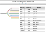
Secondary Wiring Harness
(8-Wire Connector)
Brown Wire - (Positive Siren Output): The Brown wire is a 1 Amp
Positive output designed to operate the electronic siren for audible confirmations,
and to sound if the alarm is triggered.
SIREN CONNECTION: The Brown wire may be connected directly to the
siren's Red wire, and the siren's Black wire is connected to (-) Ground.
SIREN MOUNTING: Find a location in the engine compartment away from the
extreme heat of the engine and manifold. A suitable location will offer a firm
mounting surface, will also allow sound dispersion out of the engine compartment,
and not be accessible to a thief. The siren must be pointed downward to avoid
moisture getting inside it and to enhance sound dispersal.
SIREN CHIRPS: The siren itself can be set for loud or less loud confirmation
chirps- cut the short Black wire loop on the siren for louder confirmation chirps.
The confirmation chirps volume may also be adjusted to four different volume
levels by User Programmable Feature #10. User Programmable Feature #9 turns
the chirps off completely, or it can also set the system to only chirps in valet mode,
or to chirp except when the system is in valet mode.
CAUTION! Do not exceed the output capacities of either wire-
the Brown siren wire is 1 Amp, Positive output; and the
Yellow/Green programmable horn wire output is Negative 250mA.
HORN CONNECTION: The K9-Classic-EDP can sound the vehicle’s existing
horn in addition to, or in place of, the electronic siren.
Sounding the horn alone can be accomplished by one of these means:
1) Use this Brown wire. Change Feature #15 to one of the “Pulsed” output
settings, and typically use a relay to convert the Brown wire to Negative, or
higher output, to connect to the vehicle’s horn relay wire or horn wire directly.
2) If the Factory Alarm Disarm function is not needed, program Feature #24 for
the “horn” setting and connect the Yellow/Green output wire to the vehicle
horn relay wire; or, add a relay to the Yellow/Green wire to switch higher
amperage Positive or Negative directly to the horn.
See the Universal Relay Diagram on page 22.
HORN & SIREN CONNECTION: The K9-Classic-EDP can also sound the
siren and horn together. Connect the Brown wire to the siren and connect the
Yellow/Green wire to vehicle horn as described above.

When this feature is used to remove these chirps, the system will still have 3 chirps
upon arming if a protected zone is violated, and still have 4 chirps upon disarming
if the system was previously activated. Using this feature to turn off the arm and
disarming chirps will also not affect the Prewarning operation, Unauthorized
Transmitter Alert (if used), nor will it affect the chirps used when programming.
The other two settings will have the confirmation chirps operate only when the
system is in Valet Mode, and not otherwise; or, the chirps will operate except when
the system is in Valet Mode.
Feature #12 Parking Light Illumination Upon Disarm
Factory Default Setting On (press “arm/lock” button to program)
Option: Off (press “disarm/unlock” button to program)
This feature affects the parking light operation when the system is disarmed. When
this feature is turned on, the parking lights flash once, and then turn back on for
external illumination for 30 seconds unless the ignition key is turned on during that
Page - 27
Feature #10 Confirmation Chirp Volume
Factory Default Setting Medium High
(press “II” button to program)
Options:
Low (softest) (press “arm/lock” button to program)
Medium Low (press “disarm/unlock” button to program)
High (loudest) (press “III” button to program)
This feature allows the choice of four different volume levels of the system’s con-
firmation chirps, and when programming it, the buttons can be repeatedly and
sequentially pressed, thus making it easy to hear and choose the setting with the
best chirp volume. This feature operates regardless of how feature #15, “Steady
Siren” or “Pulsed Horn” is set.
Feature #11 Alarm Duration
Factory Default Setting 30 Seconds
(press “arm/lock” button to program)
Options:
60 Seconds (press “disarm/unlock” button to program)
90 Seconds (press “II” button to program)
120 Seconds (press “III” button to program)
This feature allows four choices of the Alarm Duration, which is the period of time
for which the system sounding the siren (and/or horn, optionally) and flashes the
parking lights when it is triggered. Caution: Before lengthening the Alarm
Duration you should always check and determine if there are any local anti-
noise or nuisance ordinances to avoid the possibility of the system user receiving
a violation citation.
White Wire - (Positive Flashing Light Output): This is a Positive
12 Volt output to flash the vehicle's parking lights for visual arming confirmation,
to illuminate them for disarming confirmation, to confirm remote starting, and to
attract attention while the system is activated.
CONNECTION: Connect this wire to the vehicle's Positive 12 Volt parking
light circuit, which can usually be found at the following locations: at the headlight
switch, at the fuse/junction block, or in the rear body harness in the driver kick panel.
Some vehicles have a parking light relay which is triggered by a Negative Ground
circuit from the headlight switch; for these vehicles, simply find the Positive output
side of the stock relay for a direct connection; or, instead of this White wire use the
Yellow/Red wire programmable output in its “parking light” setting.
The correct wire will show Positive 12 Volts when the headlight switch is in the
"Parking Light" and "Head Light" positions. When such a wire is located, also test
to ensure that it is non-rheostated: meter the wire operate the dash light dimmer
control; the correct wire will show no voltage change when the dimmer is operated.
Another cautionary note is that the halogen headlights found in modern vehicles
are not designed to be rapidly turned on and off, and if connected to the security
system, a reduction of their useful life may be occur. If flashing the headlights is
still desired, a relay must be used, since the headlight's current draw exceeds the 10
amp rating of the built-in relay. If flashing headlights and parking lights are desired,
use two relays - configure one relay to supply the parking lights and the other relay
to supply the headlights.
Page - 10
Do not connect the White wire to a rheostated (dimmer) circuit!
This will backfeed the parking lights through the rheostat or illumination
control module, and possibly cause damage to the vehicle or security
system control unit. Flashing the headlights is not recommended.
Rear Body Harness
Head
Light
Switch
Junction
Block
Dash Lights
Dimmer Parking
Lights
White
wire
10 Amp
Parking
Lights
Caution: Do not connect to the dimmer circuit!
Damage can occur to the unit & the vehicle.
Recommended Connection Points For The White Wire
K-9
Control
Module

Violet Wire - (Positive Door Trigger): The Violet wire is identical to
the Green Door Trigger wire, with the sole exception that it is an open door input
to the control module for vehicles having Positive 12 volt door pin switches.
Green Wire - (Negative Door Trigger): The Green wire is an "open
door" input to the control module for vehicles having Negative switching door pin
switches. This wire is most commonly connected to the vehicle interior light
system.
CONNECTION: Connect the Green wire to a wire in the vehicle that is
common to all the door pin switches; the correct wire in this type of interior or dome
light/door jamb pin switch system will have no voltage present and will also show
chassis ground when the doors are opened, and up to 12 volts when the doors are
closed.
Page - 11
Passenger
Pin
Switch
(+)12 Volts
Driver
Pin
Switch
The Driver Pin Switch will often have
an extra wire that activates the “ignition
key in switch” warning chime. This
circuit will activate the security system,
but only from the driver's door, and is
the incorrect trigger wire >
Interior Light
Typical Negative Switching Interior Light System
This is the
correct "trigger”
wire - connection
may be made at
any point
Driver
Pin
Switch
To Chassis
Ground
Interior
Light
To Constant
12 Volt
Note: The Driver Pin Switch
will often have an extra wire;
this circuit will activate the secu-
rity system, but only from the
driver's door. This is the incor-
rect activation wire >Passenger
Pin
Switch
This is
the correct
“trigger” wire -
connection may
be made at any
point
Typical Positive Switching Interior Light System
time that the ignition switch is turned on. An exception to this would be if feature
#8 is turned on, and a door being open when the ignition switch is turned on. The
following feature #7 controls the automatic unlocking operations, and feature #8
provides for an override of this automatic locking if a door is open when the ignition
is turned on.
Feature #8 Open Door Bypass of Ignition Locking
Factory Default Setting On (press “arm/lock” button to program)
Option: Off (press “disarm/unlock” button to program)
This feature cancels the automatic locking or unlocking of the vehicle’s doors
should one of the doors is open when the ignition switch is turned on or off.
Feature #7 Doors Unlock With Ignition Off
Factory Default Setting On (all doors will unlock)*
(press “III” button to program)
Options:
Off (press “arm/lock” button to program)
Driver’s Door Only* (press “disarm/unlock” button to program)
All Doors Except Driver’s Door* (press “II” button to program)
Similar to the previous locking feature, except this feature controls the unlock
operations when the ignition is turned off, and it has more options because of the
multiple unlocking outputs of the DLS port.
*Multiple unlock outputs offer the capability of unlocking only the driver’s
door when the system is disarmed (Driver Door Priority Unlocking), and then the
option of unlocking all doors with a second press of the “disarm/unlock” button.
The driver’s door unlocking differently from the other doors must be config-
ured when the system is installed!
If the system is installed without the Driver’s Door Priority Unlocking interface,
this feature unlocks all of the doors when the ignition switch is turned off.
If Driver’s Door Priority Unlocking is installed, this feature can control only the
driver’s door unlocking when the ignition is turned, all doors unlocking, or all doors
except the driver’s. The following feature provides for an override of this automatic
unlocking if a door is open when the ignition is turned off.
Feature #9 Confirmation Chirps
Factory Default Setting On
(press “arm/lock” button to program)
Options:
Off (press “disarm/unlock” button to program)
Chirps Excepting Valet Mode (press “II” button to program)
Chirps in Valet Mode Only (press “III” button to program)
This feature removes the system’s 1 arming and 2 disarming confirmation chirps.
Page - 26

Feature #3 Automatic Rearming
Factory Default Setting Off
(press “arm/lock” button to program)
Options:
On without doors locking (press “disarm/unlock” button to program)
On with doors locking (press “II” button to program)
“Automatic Rearming” prevents the system from becoming accidentally disarmed
by having it arm itself after being disarmed, if a door is not then opened or the
ignition turned on. Options are to have Automatic Rearming operate with or without
also locking the doors when the system does rearm.
Feature #4 Starter Interrupt Functions
Factory Default Setting On
(press “arm/lock” button to program)
Options:
Off (press “disarm/unlock” button to program)
Automatic (press “II” button to program)
This feature controls the Starter Interrupt circuit, in several ways. In its default
setting, “On”, the Starter Interrupt is operable whenever the alarm is armed.
The “Automatic” option will cause the Starter Interrupt output to automati-
cally engage 90 seconds after the ignition switch is turned "off", and also 90 sec-
onds after disarming the system. This automatic engagement will occur even if the
security system is in a disarmed state, but not if it is in Valet Mode. Once the
Starter Interrupt output is activated, the system must be armed, then disarmed with
the controller or transmitter, or placed into the Valet Mode by pressing and holding
the Valet Switch for 2 seconds to disengage it. There are no Status Light indica-
tions with this automatic form of Starter Interrupt.
Programming this feature “Off” completely eliminates the Starter Interrupt
output, while leaving all other system operations fully functional.
Feature #5 Ignition Activated Override
Factory Default Setting Off (press “disarm/unlock” button to program)
Option: On (press “arm/lock” button to program)
This feature allows an activated system to be overridden and disarmed by simply
turning the ignition switch on within 10 seconds of the system’s activation. After
10 seconds, the Emergency Override must be performed or the controller or trans-
mitter “disarm/unlock” button can be used to disarm the system.
Page - 25
Feature #6 Doors Lock With Ignition On
Factory Default Setting On (press “arm/lock” button to program)
Option: Off (press “disarm/unlock” button to program)
This feature configures the system to automatically lock the vehicle’s doors every
Page - 12
The correct wire for a Positive switching type of dome light/door jamb pin
switch system will have 12 volts present when the doors are opened, and chassis
ground when the doors are closed.
CONNECTION: Connect the Violet wire to a wire in the vehicle that is
common to all the door pin switches; the correct wire for this type of dome light/door
jamb pin switch system will have 12 volts present when the doors are opened, and
chassis ground when the doors are closed.
Notes and Tips, both types of Interior Light or Door Trigger
circuits: The correct wire will show this change when any of the doors are
opened. If the vehicle has delay-off or “fade away” interior lights, remember
to take this into account when testing the wire. If the pin switch is mounted in
the metal structure of the vehicle, and the interior lighting goes out when the
switch is removed, suspect a grounding switch-type lighting system.
Switches controlling interior lighting may be found in several locations-
the front or rear door jamb area, as the traditional “pin switch” or sliding
switch; or as switches inside the doors, either connected to the exterior door
handles or to the latching mechanism. A vehicle which has the interior lights
illuminating when the outside door handle is lifted is an example of this type
of switching system.
Also be aware of vehicles which diode-isolate each door. Typically, this
is usually encountered with dash displays that indicate individual doors being
ajar. The proper wire to connect to in this type of system is the common wire
which is routed directly to an interior light that illuminates when any door is
opened.
Green/Violet - (Domelight Supervision Output) &
Black/Red - (Domelight Supervision Input) Wires:
Domelight Supervision offers an additional safety and security feature- upon
disarming the system the interior lights will turn on to illuminate the interior. The
Green/Violet wire is the output to turn on the lights, and the Black/Red wire is
input, connected to Positive or Negative polarity which is needed for operating the
interior light.
For reference, see the diagrams on the previous page showing the basic
differences between Negative and Positive interior light circuits.
CONNECTION GREEN/VIOLET: The proper vehicle wire to connect the
Green/Violet wire to, the dome light activation wire, is common to all the door pin
switches. The correct wire will change polarity as the doors are opened and closed.
The dome light activation wire in the vehicle is typically the same wire that the

To custom program a new SecureCode:
Step 3 After entering the first stage by pressing the “arm/lock” button the
desired number of times, and receiving a chirp for each press, wait for the
Step 2 Within 10 seconds slowly press and release the controller or transmitter’s
“arm/lock” button the number of times equal to the desired SecureCode
for stage 1, allow the system to respond to each controller/transmitter
button press with a siren chirp before pressing the button again.
Step 1 Follow Steps 1 to 4 in the previous “How to Program Features” instruc-
tions; at Step 4 the Valet Switch will be pressed and released once (the
siren chirps once) to access “feature #1”.
Feature #1 SecureCode
Factory Default Setting 1 Press
Options:
1 to 9 presses, in each of two stages
Step 4 Continue to configure stage 2 of the SecureCode by now pressing and
releasing the “disarm/unlock” button the number of times desired for the
stage 2. This should be done in the exact same fashion as the stage 1 entry-
press the “disarm/unlock” button, wait for a single chirp before pressing
the button again, and then when final button press is done, wait after the
single chirp for the siren to chirp the total number entered Valet Switch
entry.
system, after the final button press, to chirp the siren again the total
number of times that the button was pressed.
Feature #2 Last Door Arming
Factory Default Setting Off
(press “arm/lock” button to program)
Options:
On without doors locking (press “disarm/unlock” button to program)
On with doors locking (press “II” button to program)
“Last Door Arming” has the system automatically arm itself every time the operator
exits the vehicle and closes the door. This feature turns that operation on or off, and
with options of having Last Door Arming operate with or without also locking the
doors when the system does arm.
SecureCode is a unique patented feature which allows the user to custom select the
number of Valet Switch presses in two stages, instead of a single “1 press”, which
would be required in order to perform an Emergency Override. If any of the three
anti-carjacking features are utilized, a customized SecureCode would also be
required to turn the alarm off once it is fully activated. The SecureCode operation
is described in detail the Operations Guide.
Page - 24
Green or Violet wire is connected to, for the door trigger.
If the vehicle uses a Negative switching interior light system, the activation wire
will have no voltage present and show chassis ground when the doors are opened,
and up to 12 volts when the doors are closed. The correct wire for a Positive
switching type of interior light/door jamb pin switch system will have 12 volts
present when the doors are opened, and chassis ground when the doors are closed.
The correct wire will show these changes when any of the doors are opened. If the
vehicle has delay dome lights, remember to take this into account when testing.
CONNECTION BLACK/RED: The polarity of the dome light supervision
output must be selected by the connection of the Black/Red wire as Positive or
Negative. Connection of the Green/Violet should have determined which polarity
the vehicle uses to operate the dome light; this is either "Negative switching" or
"Positive switching" (see the diagrams on page 11). Once “Positive switching” or
“Negative switching” has been determined, connect the Black/Red wire to Negative
(for “Negative switching” interior lights) or to Positive (for “Positive switching”
interior lights).
"Smart Trigger": The K9-Classic-EDP has a unique "Smart Trigger"
feature which saves installation time while offering enhanced integration
flexibility. The Green/Violet Domelight Supervision output wire has an
additional function; it can also be used as a door trigger input circuit, serving the
same purpose as either the Green or Violet door trigger wires.
If the Smart Trigger feature is used, it is not necessary to connect either the
Green Negative Door Trigger or the Violet Positive Door Trigger wire,
provided the Green/Violet Domelight Supervision output wire is connected
correctly.
CONNECTION:
Page - 13
K-9
Control
Unit
Jumper
to left
to left
Jumper
(-) Negative
Green/Violet
Ground
10 Amp
Black/Red
Dome Light Wire
Dome
Light
Negative Dome Light
Smart Trigger
Connection
The Smart Trigger
jumper must be set for
(-) Negative polarity
continued next page

Page - 14
Blue Wire - (Negative Instant Trigger): The Blue wire is a Negative
instant trigger used to detect entry into the hood or trunk area of a vehicle.
CONNECTION: The included pin switches may be installed to provide this
trigger circuit; or, if there are existing switches the Blue wire may be connected
directly, provided this is a negative ground switching circuit (examples: an OEM
antitheft hood switch, or in the case of the trunk or hatch a light in the luggage
compartment or a "Trunk Ajar" light in the dash).
An indication of such a circuit is the wire having no voltage present when the
hood or trunk is open, and up to 12 volts when the hood or trunk is closed. This wire
If use of the Smart Trigger feature is not desired, remove completely the
polarity selection jumper. Doing so separates the dome light supervision
circuit from the door trigger circuits. The Black/Red and Green/Violet wires
may then be connected for the Domelight Supervision only, and either the
Green Negative Door Trigger or the Violet Positive Door Trigger wire must be
connected for the system's door trigger. In some cases, when opting for
automatic rearming or last door arming, it may be preferable to not use the
Smart Trigger, and connect the appropriate door trigger wire for the best
operation of the automatic arming or rearming feature.
The Smart Trigger feature may be used or not used, as desired by the installer.
If Smart Trigger is utilized, please note that the polarity must be programmed
(via the jumper connector on the side of the control module) for "positive
switching dome light" or "negative switching dome light".
Green/Violet
To Constant
12 Volt
10 Amp
Black/Red
Dome Light Wire
K-9
Control
Unit
Jumper
to right
Dome
Light
to right
Jumper
(+) Positive
Positive Dome Light
Smart Trigger
Connection
The Smart Trigger
jumper must be set for
(+) Positive polarity
The Programmable Features
Page - 23
- SEE PAGE 32 FOR PROGRAMMING INSTRUCTIONS -
Each Programmable Features is described in detail in this section, then
Programming instructions follow, which include a handy Features’
matrix showing the Features and all programming options.
This group of User Programmable Features are all accessed as a group in the first
level of features’ programming. These features have a direct affect upon the
system’s operations, so the programming and operation of each are described.
The K9-Classic-EDP’s 24 Programmable Features:
1 SecureCode
2 Last Door Arming
3 Automatic Rearming
4 Starter Interrupt Functions
5 Ignition Activated Override
6 Doors Lock With Ignition On
7 Doors Unlock With Ignition Off
8 Open Door Bypass To Previous Two Features
9 Confirmation Chirps
10 Confirmation Chirp Volume
11 Activated Alarm Cycle
12 Lights On Upon Disarm
13 Disarm Alarm Upon Trunk Release
14 Arming Delay
15 Steady Siren Output / Pulsed Horn
16 Alarm Functions Bypass
17 Ignition Activated Anti-Carjacking Protection
18 Door Activated Anti-Carjacking Protection
19 Remote Activated Anti-Carjacking Protection
20 Open Door Warning Upon Arming
21 III Button Operation
22 Doorlock Functions
23 Factory Alarm Arm Output
24 Factory Alarm Disarm Output
Use the step-by-step instructions on page 42, and the complete features matrix
on page 43, to change any of the programmable features. Each feature, the option
choices and related programming controller/transmitter button assignment are
described in detail in the following pages.

Page - 22
Omega data bus interface modules, and remote start bypass modules, are
available as analog-operated, and as direct data-to-data (D2D) devices. The former
may be operated by connection to the DLS port. The later are the Omega IntelliKit
data bus interface modules and bypass kits, which simply plug into this Green port.
Either type of Omega accessory module includes its own vehicle-specific instructions.
Please refer to the Omega website, www.caralarm.com, for the latest vehicle-
specific application guide. Although other brands of data bus modules may
physically plug into the K9-Classic-EDP data port, only genuine Omega
IntelliKit modules offer the highest consistent quality and dependable operation.
Always choose Omega databus products for use with this port.
Data Port
(Green 4-Pin Port)
Arm/Disarm, Options Port
(Orange 2-Pin Connector)
This Orange 2-pin port has a pair of outputs, Factory Arm and Disarm, which
are also programmable for several other functions (see Features #23 and #24).
These are 250mA (-) Negative outputs. Use a relay if needed to increase these
outputs or reverse their polarity.
CAUTION! Do not exceed the output capacities of either wire-
both outputs are rated at (-) Negative 250mA.
Pin 30 is INPUT,
also known
as Common.
30
86 87a 85
87
Universal Relay Diagram
Pin 86 and Pin 85 are the relay’s Coil pins.
(+) Positive and (-) Negative 12 volts on these pins
activate the relay. It is a good installation
practice to consider
Pin 86 as (+) and
Pin 85 as (-).
Pin 87a is OUTPUT
when the relay is NOT
actived, also known
as Normally Closed.
Pin 87 is OUTPUT when
the relay IS actived, also
known as Normally Open.
“footprint” view, as looking at relay
may be used with a mercury type of tilt switch, by itself, but it cannot be used with
existing hood or trunk lights which have an internal mercury switch. If the vehicle
is equipped with a usable trunk or hood circuit, locate the proper wire and splice the
Blue wire directly to the vehicle's wire. If not, then you can install a pin or mercury
switch and carefully adjust and test it.
Multiple use of the Blue wire: When wiring more than one of the vehicle's
circuits and/or additional circuits to this wire, diode-isolation is usually required to
maintain each circuit's proper independent operation. An example would be wiring
a hood pin switch and trunk light switch together. Without isolating, the trunk light
will illuminate whenever the hood is raised. Also, diode-isolation is necessary when
combining electronic sensors together, or when adding a sensor in the same circuit
as the pin switches.
Blue (-) Instant Trigger Wire.
Use IN4002 Diodes to isolate
each switch or device
Trunk
Pin
Switch
Hood
Pin
Switch
Trunk
Light
Diode-Isolating Multiple Negative Instant Triggers
K-9
Control
Module
Optional
Electronic
Sensor
Pink Wire - (Negative 3rd Channel or Option Output): The 3rd
Channel Pink wire is an optional output similar to the 2nd Channel Gray trunk or
hatch release wire; however, this output is not capable of disarming the system when
it is used and therefore has no audible or visual confirmation.
CONNECTION: For most applications an optional relay will be needed;
typical connection is the Pink wire to relay pin #85, and connect Constant Positive
12 Volts to relay pin #86. Connect pin #30 to power, or ground, as needed. Pin #87
is the output, and connected to the target wire. See the Universal Relay Diagram
on page 22.
Page - 15

Page - 16
Accessory Wiring Harness - DLS Port
(Red 4-Pin Connector)
Plug-In DLS Power Doorlock Interface Port: The Red 4 pin port on the
system's control module produces a negative pulse output for locking the doors, a
constant 12 volt pin for the optional relay coils only, a first negative pulse output
for driver door unlock, and a second negative pulse output for unlocking all other
doors.
The vast majority of power doorlocks are found as three system types: 3 wire
negative pulse, 3 wire positive pulse and 5 wire reversal, rest at ground. Other power
doorlock systems which may be encountered are the vacuum pump types found in
older Mercedes vehicles and the single wire, dual-voltage which has appeared in
some late model vehicles. The best way to identify a doorlock system is to examine
the doorlock switch's wiring.
3 Wire Negative Pulse Systems are typically indicated by the presence of
three wires at the switch. Of these, one will show constant ground, regardless of
whether the switch is being operated or not (at rest); one will show ground when the
switch is pushed to the "lock" position, and the other wire will show ground when
the switch is pushed to the "unlock" position. With the switch at rest, these two wires
will read voltage, usually 12 volt positive but in some cases less. The wires from the
switches operate doorlock relays or a doorlock control unit with built-in relays;
make the connections between the switches and the relays.
CONNECTION: The included harness (DLP-N4) can allow direct connection
between the security system and a 3-Wire Negative Pulse system. If more than the
500mA Ground output that the security module can provide is required, use the
optional model DLS and two relays. When driver's door unlock priority is desired,
use the optional DLS-3.
3 Wire Negative
Doorlocks using
the Control Unit
Outputs Door
Motors
Green wire to
Switch Lock wire Blue wire to
Switch Unlock wire
Vehicle's Doorlock
Relay Control Unit
Doorlock Switch
Unlock
Lock
Pink Wire is not used
Ground
DLP-N4 harness (included) Red
connector plugs into the
control module’s Red DLS port
Page - 21
The two later wires are both routed to the doorlock actuators and are connected
to either end of the actuator's motor winding. When the switch is pushed to one
position, one of these two wires will have 12 volts. This voltage flows through the
wire to the actuator's motor winding, and since the other wire is still resting at
ground an electrical circuit is completed. When the switch is pushed to the opposite
position the electrical flow is reversed.
Once determined, the correct wires must be cut. Notice in the diagram that the
driver's switch is the primary switch and referred to as the "switch" wires. The wires
that go to the secondary switch are referred to as the "motor" wires. Even though
the cut is made between the switches, the two sides are still correctly called the
"switch" and the "motor" sides, with consideration of "Primary" and "Secondary"
switch.
The K9-Classic-EDP features backup battery capability. Included with each is
a slide-on clip mounting bracket and a snap-cap wiring harness for an optional
alkaline 9 volt battery. If the alkaline 9-volt battery is used, it should be replaced
with a fresh battery about every year for best system backup performance.
Also available is an optional rechargeable battery pack, which if used would be
a permanent backup power supply, not requiring occasional replacement.
Backup Battery Port, Harness and Bracket
(White 2-Pin Connector)
To add the backup battery feature:
1) Assemble the backup pack (instructions are with the bracket and harness)
with an optional alkaline 9-volt battery, slide the assembly onto the alarm
control module, and then plug the 2-pin wiring harness into the White 2-pin
port on the module.
OR
2) Or if the optional rechargeable pack is chosen, it is pre-assembled and be
attached to the alarm control module in the same fashion, by sliding it onto
the control module. Insert the battery pack’s 2-pin plug into the alarm’s
White backup battery port, and connect its remaining single Red wire
directly to Constant (+) Positive 12 volts.
Install the included impact sensor according to the instruction sheet included
with it, and then plug its wiring harness into the alarm control module’s White 4-
pin port (be cautious to not plug the White sensor connector into the Red DLS
doorlock output port).
Sensor Port
(White 4-Pin Port)

Page - 20
5 Wire Reversal Rest At Ground Systems differ from the Negative and
Positive Pulse systems as there are no relays or doorlock control unit. In this type
of system, the switches themselves supply the positive voltage directly to the
doorlock actuators, and, more importantly, provide the return ground path. The
important thing to remember is the wires in this system rest at ground, which means
that the wires must be "opened", or cut, to make the connections.
Examine the wires on the back of the switch. Normally five wires will be found-
one will be constant 12 volts positive, regardless of the switch's position; two wires
will be grounded regardless of the switch's position. Of the two remaining wires,
one will show 12 volts positive when the switch is pushed to "lock", and the other
will show 12 volts positive when the switch is pushed to "unlock".
DLS Red connector
plugs into Control
Unit
Green wire
to the "Motor"
side of the
cut “lock” wire
Blue wire
to the "Motor"
side of the
cut “unlock” wire
Cut both the “lock”
and “unlock” wires*
Brown wire
to the "Switch"
side of the cut
“unlock” wire
White wire
to the "Switch"
side of the
cut “lock” wire
Lock
Unlock
Driver
Doorlock
Switch
Lock
Unlock
Passenger
Doorlock
Switch
Cutting only one of two wires can cause
misleading test results. For example, if
only the “lock” wire is cut, the “switch”
side of the cut will show (+)12 Volts when
the primary switch is pushed to the "lock"
position and the “motor” side of the cut
will show (+)12 Volts when the primary
switch is pushed to the "unlock" position.
Passenger
Motors
Driver
Motors
DLS
Relay Relay
5 Wire Reversal Doorlocks
using the Optional
DLS & 2 Relays
DLS Violet Wire
to Constant
(+)12 Volts
3 Wire Positive Pulse Systems are very similar to the Three Wire Negative
Pulse system except the vehicle's doorlock switches use 12 volt positive pulses to
operate the vehicle's doorlock relays or control unit. Examine the three wires on the
back of the switch; if more than three, suspect a 5 Wire Reversal system. One will
be constant 12 volt positive, regardless of the switch's position. Of the two
remaining wires, one will show Positive when the switch is pushed to "lock", and
the other will show Positive when the switch is pushed to "unlock".
CONNECTION: Several options are available for connecting to 3 Wire
Positive Pulse doorlocking systems- the DLP-P3 polarity reversal interface, the
DLS and two relays or the DLR-C or DLR-U. If driver's door unlock priority is
desired, use the optional DLS-3. The following diagrams show how to connect
either of the optional DLP-P3 or the DLS and 2 relay interfaces.
Page - 17
Doorlock Switch
DLP-P3 Blue wire to
switch “unlock” wire
DLP-P3 Green wire to
Switch “lock” wire
Vehicle's Doorlock
Relay Control Unit
Unlock
Lock
3 Wire Positive Pulse
Doorlocks using an
Optional DLP-P3
Polarity Converter Door
Motors
D/U+
D/L+
DLP-P3 Red connector
plugs into the control
module’s Red DLS port
DLP-P3
Door
Motors
Doorlock Switch Vehicle's Doorlock
Relay Control Unit
Unlock
Lock
+12V
3 Wire Positive Pulse
Doorlocks using an
optional DLS &
2 SPDT Relays Relay
DLS
Relay
DLS Blue wire to
Switch “unlock” wire
DLS Green wire to
Switch “lock” wire
DLS Violet Wire
to Constant
(+)12 Volts.
DLS Brown & White wires
are not used in this system
DLS Red connector
plugs into the control
module’s Red port
Text continues on Page 20

Page - 18
Status Light
Valet Switch
Wiring Diagram
Overview
Starter Interrupt
socket and relay
To StarterTo Ignition
Switch
White
Red
cut wire
15 AMP
Main Wiring Harness Connector
(-) 2nd Channel Output (trunk release) - Gray
Ignition Power Input - Yellow
System (-) Ground - Black
To Constant (+) Power - Red
Secondary Wiring Harness Connector
(-) 3rd Channel Output - Pink
(-) Door Trigger Input - Green
(-) Hood Trigger Input - Blue
(+) Door Trigger Input - Violet
(+) Siren Output - Brown
(+) Parking Light Output - White
Interior Light Output - Green/Violet
(+ or -) Interior Light Input - Black/Red
10 AMP
(-) Starter Interrupt Output - Orange
Main
Harness
8-Pin 5-Pin
Secondary
Harness
Backup
Battery
Port Slide-On Clip for
optional modular
Backup Battery
Coaxial Antenna Cable: Route end as
high as practical in vehicle, away from metal.
Data
Port
(-)
(+)
Orange 2-pin Connector
Factory Alarm Disarm - Yellow/Green
Factory Alarm Disarm - Yellow/Red
Auxiliary Sensor Port
Green - Prewarn
Blue - Trigger
Black - Ground
Red - Power
Power Doorlock Port
Pink - Unlock #2 Output
Blue - Unlock #1 Output
Relay Coil Power (pin)
Green - Lock Output
Red 4-pin Connector
White 4-pin Connector
Impact
Sensor
10 AMP
(-)
(+)
Smart
Trigger
Jumper
K-9
Classic-EDP
CAR ALARMS
Note: The K9-Classic-EDP may be upgraded to
2-way operation by an optional Omega Echo kit.
Jumper
Plug for optional
2-way Echo
Page - 19
/