Page is loading ...

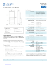
HVAC Setback Module
Installation Guide
Model: EHSM
Package Contents
▪ HVAC Setback Module
▪ Double-sided adhesive
pad
Product Description
The HVAC Setback Module is a simple way to save energy by
switching HVAC units between normal and setback modes.
It is low voltage, mounts easily in a typical HVAC enclosure,
and communicates wirelessly with EnOcean wireless occupancy
detection and lighting control products.
Features Include:
▪ Switches HVAC to setback mode to save energy
▪ Powered by HVAC via standard 24 VAC connection
▪ Receives wireless messages from EnOcean-based devices to
determine room occupancy
▪ Controls setback range by built-in temperature sensor
▪ Provides simple input signal by dry contact to compatible
HVAC systems
▪ Concealed easily within HVAC enclosure
▪ Sends wireless messages to other controlled devices; con-
gurable transceiver
Specications
Power Supply 9-30 VAC, 12-40 VDC
Maximum Load 1A @ 24 VAC/VDC
Temperature
Sensing Range
Temperature Sensing Range
32° to 104° F (0° to 40° C)
Temperature Sensor
Accuracy
± 1.8° F @ 50° to 90° F
(± 1° C @ 10° to 32° C)
RF Communications EnOcean 902 MHz (EHSMU)
EnOcean 315 MHz (EHSMC)
Interoperable Products /
EEPs (EnOcean
Equipment Proles)
[Product Name (EEP #)]
Rocker Pad Switch (F6-02-02)
Key Card Switch (F6-04-01)
1BS Single Input Contact (D5-00-01)
Temperature Sensor, 0 - 40° C
(A5-02-05)
Occupancy Sensor (A5-07-01)
Occupancy Sensor (A5-07-02)
Occupancy Sensor (A5-07-03)
Contact, single input (A5-30-02)
Dimensions 2.57” H x 1.65” W x 1.10” D
(6.5 cm x 4.2 cm x 2.8 cm)
Weight 1.9 oz. (54 g)
Mounting • Install inside standard electrical box
• Connect to electrical boxes and
xtures using threaded nipple
Environment • Indoor use only
• 32° to 104°F (0° to 44°C)
• 20% to 95% relative humidity
(non-condensing)
Agency Compliance ETL, FCC, IC
Planning
Take a moment to plan for the module’s successful operation
and optimal communication with other system components.
▪ Always use a qualied installer
▪ Review HVAC unit’s manual to assess control compatibility
▪ Identify the high voltage wiring and how to disconnect it lo-
cally and at the circuit breaker panel
▪ Identify a location in the HVAC enclosure that is free from
housing obstructions and as far away as possible from the
HVAC unit’s control panel to avoid signal interference
▪ Make sure the wires are straight (avoid loops and coils)
▪ Take care not to damage the radio antenna that runs in a
groove on the front side of the module
▪ Consider the construction materials in the space and ob-
stacles that may interfere with RF signals
Installing
Read and understand instructions completely before starting.
ELECTRICAL SHOCK HAZARD
High Voltage. This device must be installed by
a qualied installer or electrician. Follow all ap-
plicable electrical codes for installation.
Tools Required
▪ Owner’s manual for the
HVAC model
▪ Wiring connectors, type
varies per HVAC model
Page 1© 2013 EnOcean GmbH

1. Turn o power at the circuit breaker or unplug the HVAC unit
and test that power is o.
2. Consult the HVAC unit’s manual to:
A. Safely remove the enclosure and any obstructions that
prevent access to the wiring.
B. Conrm the HVAC unit has the
required control input, typically
called, front desk or energy
management.
C. Identify low voltage output to
power the module.
D. Identify the type and the num-
ber of control terminals. Each
HVAC brand uses their own ter-
minal codes, e.g.: FD1, FD2, CDC1, CDC2, or EMS1, EMS2.
E. Identify the appropriate electrical connectors: terminal
screws or pins, butt splice connectors, wire nuts.
3. Connect the module’s Red and Black wires to the low voltage
power output from the HVAC unit.
4. Connect the module’s Yellow wires to the appropriate control
terminals of the HVAC unit.
5. Apply double-sided adhesive pad to the back of the module.
TIP: To avoid distorting the temperature sensor, do not install
the module in the path of blowing air.
NOTE: It may be easier to link and congure devices before
mounting the module, see the Linking and Conguring
sections.
6. Attach the module to the inside
wall of the HVAC enclosure and
position it so you can access the
setup interface (buttons/LEDs).
TIP: To limit the potential risk of
signal interference, position the
module within the enclosure as far
away as possible from the unit’s
control panel.
7. Restore power to the circuit.
The LEDs on the module will blink and then the right LED will
display solid red when the relay is open, or green when the
relay is closed (setback engaged).
Linking
Two or more compatible devices can be linked and congured
to provide the desired control. There are two basic types of
devices in the system; transmitters and transceivers.
▪ Transmit-only: Transmitters are simple energy-harvesting
devices that send RF messages to communicate a condition,
level, or state. Transmitters can only be linked to transceivers.
Examples > Self-powered Light Switches, Occupancy Sensors
▪ Transmit & Receive: Transceivers are controlling devices
that send as well as receive RF messages. They also process
relevant control logic, and actuate the appropriate outputs
(switching a light on or o for example). Transceivers can be
linked with transmitters as well as other transceivers. A trans-
ceiver can have up to 30 devices linked to it.
Examples > Relays, Gateways
The HVAC Setback Module is a Transceiver
(transmits & receives)
To link the occupancy sensor to a transceiver; the transceiver
must rst be powered, within wireless range of the controls it is
to be linked to, and set to accepts links.
Next, the desired transmitter, or another transceiver, is triggered
to send a special link message. The awaiting transceiver receives
and stores the link permanently so the devices can interact to
provide a variety of intelligent control options.
About the Setup Interface
The setup interface has two buttons, Menu and Set, that each
have a corresponding 3-color LED (green, amber, red). This sim-
ple interface is used to link and congure devices as a system.
The buttons and LEDs are used to navigate and select linking
and setup options through a 3-tier menu system consisting of
dierent Modes > Menus > Options.
To use the interface, hold the module so both thumbs can click
the buttons without obscuring the LEDs. The illustration and
legend below describe how the buttons are used and the mean-
ing of the LED responses.
To exit from anywhere in a menu, hold both buttons at the same
time for 2 seconds.
HVAC Setback Module • Installation Guide
Page 2
Example installation - HVAC
Setback Module is away from
control panel. Wires are routed
under the HVAC unit and con-
nected to control terminals at
the other end.
HVAC Setback Module
Control
Panel
Relay input
Isolated
Normally-Open
Relay Contact
Power input
9-30 VAC
12-40 VDC
© 2013 EnOcean GmbH

The Menu LED or Set LED display solid for a number of sec-
onds in a certain color to indicate a mode or a conrmation.
The Menu LED blinks a number of times in a color to indi-
cate a selected menu.
The Set LED blinks a number of times in a color to indicate
an option.
A number in a white box indicates the number of times to
click the Menu button or Set button.
A number in a black box indicates the number of seconds to
hold down the Menu button or Set button.
To link a transmitter to a transceiver
1. Access Basic Setup mode.
NOTE: By default, the Accept Link option in the Linking
menu is selected. Once activated, this option stays active for
two minutes to provide time to link multiple devices.
Ready to accept links.
2. For the transmitter to be linked, do one of the following ac-
cording to the type of device:
A. Sensor: click the designated link button.
B. Key Card Switch: insert/remove the card 3 times quickly.
C. Rocker Pad: click the top button 3 times quickly.
Device linked successfully.
Set LED displays solid
green for 3 seconds.
Ready to accept new links.
D. To exit mode and return to normal operation, press and
hold both buttons for 2 seconds.
To unlink a device
Follow the same steps as described in the “To link...” section
above with the following deviations:
▪ After step 1 in the “To link...” section above, click the “Set”
(right) button 3 times to enable the “Remove Link” option.
Ready to remove links.
▪ Follow the same instructions as shown in Step 2 of the “To
link...” section. The Set (right) LED will turn red briey to indi-
cate the link was successfully removed.
To restore factory defaults
Follow these steps to clear all linked devices and restore the
HVAC Setback Module to its factory default settings.
1. Press and hold both buttons for 15 seconds
>> Hold buttons until the Menu (left) LED is solid RED and
the Set (right) LED is solid Amber (Both LEDs will turn various
colors as the module cycles through the resetting process.
2. Press and hold the Set (right) button for 3 seconds to con-
rm factory reset.
3. Device will reboot and initiate start up LED sequence.
Conguring
The default settings on the module support common control
and installation scenarios. However, some setback and occu-
pancy settings can be adjusted on the module using the setup
interface, if required.
Setting
Default Application
Heat Setback
40°F (5°C) If setback range is managed by
the HVAC unit.
Cool Setback
Disabled If setback range is managed by
the HVAC unit.
Vacancy Check
5 minutes If linked to a occupancy senor
and a door sensor.
Door/Window Ajar
2 minutes If linked to an occupancy sen-
sor.
Egress
30 seconds If linked to a key card switch.
Temperature Setback Points
The heating and cooling setback points determine a tempera-
ture range where the HVAC system will remain inactive when
setback is engaged.
If the ambient temperature
exceeds the setback range,
the HVAC system will override
the setback to avoid tempera-
ture extremes. By default, the
setback range is managed by
the HVAC system. However, the
HVAC Setback Module includes
a built-in temperature sensor
which can be used to control
the setback range when appli-
cable.
From the Heat and Cool
Setback menus, the active
option is indicated by the
number of green blinks on the
Set LED; amber blinks indicate
an unsaved change. Click the
Set button an appropriate
number of times to select an
option.
Note: The temperature sensing accuracy of the HVAC Setback
Module is only ensured when powered at 24VAC. If another
voltage is used, such as 12VDC, an external temperature sensor
is recommended for improved accuracy.
Note: The ability of the HVAC Setback Module to accurately
sense ambient room temperature is highly dependent on where
it is installed. Installing the device where it may be subject to lo-
cal heat/cool sources, will distort the setback range accuracy.
Heat Options Clicks Blinks
Disabled
66°F (19°C)
62°F (17°C)
58°F (14°C)
40°F (5°C)
(default)
Cool Options Clicks Blinks
Disabled
(default)
76°F (24°C)
80°F (27°C)
84°F (29°C)
88°F (31°C)
HVAC Setback Module • Installation Guide
Page 3© 2013 EnOcean GmbH

To set a temperature range:
This examples shows changing the heat setback from Disabled
to 62° F, and changing the cool setback from Disabled to 76° F.
1. Access Advanced Setup mode.
2. Select the Heat Setback menu.
3. Select an option.
4. Save the selection.
5. Select the Cool Setback menu.
6. Select an option.
7. Save the selection.
Vacancy Check
The vacancy check is a time delay that is activated when a door
opens and closes. The linked loads will turn o, if the sensor(s)
do not conrm occupancy within the time delay.
From the Vacancy Check
menu, the active option is
indicated by the number of
green blinks on the Set LED;
amber blinks indicate an
unsaved change. Click the Set
button an appropriate number
of times to select an option.
To change the vacancy check option:
This example shows changing the option from 5 to 15 minutes.
1. Access Basic Setup mode.
2. Select Vacancy Check menu.
3. Select an option.
4. Save the selection.
To enable the device as a repeater
In some situations, enabling the transceiver device as a repeater
can help optimize the wireless range between devices.
1. Access Advanced Setup by holding both buttons down for 5
seconds and releasing them when both LEDs turn amber.
2. Click the Set button an
appropriate number of
times to select an option.
>> By default, the rst
menu option in advanced
setup is to Enable Repeater.
Option Clicks Blinks
5 mins. (default)
15 minutes
30 minutes
60 minutes
120 minutes
Option Clicks Blinks
Disabled
(default)
1 Hop
2 Hops
Example: Setting a device to operate as a repeater.
1. Access the Advanced setup (hold down both buttons for 5
seconds - until both LEDs turn amber).
2. Select “option 2” by clicking the Set (right) button two times.
(Set button LED will blink 2x (amber) to conrm)
3. Save selection by holding Set button for 2 seconds.
4. Exit Menu (hold both buttons for 2 seconds.)
5. Re-boot module by either power cycling or pressing and
holding both buttons for 10 seconds (release when Left
LED=Red, Right LED=Green).
Troubleshooting
Problem Solution Checklist
The device does not
power up
▪ Check the wiring for errors
▪ Check the circuit breaker
▪ Use a voltage meter to conrm power
The device does not
control linked load
▪ Click the Set button to open/close the relay
manually
▪ Turn o the power and then restore it
Cannot link other
devices
▪ Check if Accept Link option can be accessed
▪ Move closer to the device; it may be out of
range
▪ Try linking a dierent device
▪ Check for environmental conditions that inter-
fere with RF signals
▪ Verify the maximum number of devices (30)
has not been exceeded
Cannot change set-
tings on the device
▪ Check if menu item can be accessed
▪ Check if changes can be saved
The device does not
respond to wire-
less messages or
selected settings
▪ Check for environment or range issues
▪ Verify the device is linked
▪ Check if appropriate devices are linked accord-
ing to good system planning
▪ Extend the antenna to amplify the range:
remove it from the groove in the module,
straighten it and slide it into the white antenna
sleeve provided
Contains: FCC: SZV-STM300U (900 MHz) FCC: SZV-STM300C (315 MHz)
IC: 5713A-STM300U (900 MHz) IC: 5713A-STM300C (315 MHz)
This device complies with part 15 of the FCC rules and Industry Canada ICES-003. Operation is subject
to the following two conditions: (1) This device may not cause harmful interference, and (2) this device
must accept any interference received, including interference that may cause undesired operation.
IMPORTANT! Any changes or modications not expressly approved by the party responsible for
compliance could void the user’s authority to operate this equipment.
Le présent appareil est conforme aux CNR d’Industrie Canada applicables aux appareils radio exempts
de licence. L’exploitation est autorisée aux deux conditions suivantes: (1) l’appareil ne doit pas produire
de brouillage, et (2) l’utilisateur de l’appareil doit accepter tout brouillage radioélectrique subi, meme
si le brouillage est susceptible d’en compromettre le fonctionnement.
IMPORTANT! Tous les changements ou modications pas expressément approuvés par la partie
responsable de la conformité ont pu vider l’autorité de l’utilisateur pour actioner cet équipment.
HVAC Setback Module • Installation Guide
Page 4© 2013 EnOcean GmbH
V2.3 XHSMIGEOA
/