Page is loading ...

LED Zone Controller 0-10V Installation Guide
© 2017 EnOcean GmbH V2.0 Page 1
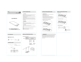
Package Contents
Tools Required
n
LED Zone Controller
n
Screwdriver
n
Wire nuts
Product Description
The LED zone controller (LEDD) uses wireless technology to
communicate with other self-powered EnOcean based
products and provides an amazingly simple solution for
dimming control of LED lighting.
LEDD is directly supplied from the auxiliary 12V supply
output of a connected LED driver. Its compact size enables
flexible installation inside of or next to electrical boxes and
fixtures so it can be easily wired out of sight using standard
wiring practices.
Simply link the module to an EnOcean-based motion sensor,
light level sensor or rocker switch and experience levels of
efficiency and convenience that can only be achieved
through wireless controls.
It is also possible to link LEDD to a central controller or via a
gateway to building automation systems like BACnet.
Product Features Include:
n Enables wireless dimming of a single fixture or a zone of
multiple daisy chained LED fixtures (e.g. 20 each 30W or
10 each 60W).
n Supports California Title 24 daylight harvesting scenarios,
occupancy control and manual dimming with input from
self-powered wireless switches and sensors. Implements
load shedding initiated by separate Demand Response
Controllers
n Installs inside or mounts to electrical box using threaded
connector
n Supports wireless remote commissioning to link devices
and set parameters
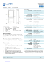
Specifications (typ. values)
Power Supply
11.0 V – 13.2 V DC
Supply Current (typ)
16 mA @12VDC supply (no sourcing)
38 mA @12VDC supply
(10V/20mA sourcing)
Power Consumption
< 200 mW @ 12 V DC
(excluding 0-10V sourcing power)
< 460 mW @ 12 V DC
(at maximum 0-10V sourcing power)
0-10V output
Tolerances +3%/-4% (1-10V range)
Current sourcing / sinking 20 mA*
* F
or high sinking current and dim value settings
below 1V, the output voltage may exceed the
selected output value and reach 1V max.
Inputs/Outputs
Flying-lead style wires:
n
2 power input wires
n
2 output wires for 0-10V control
Local User Interface
2 Buttons, 1 LED for device
configuration & manual control
RF Standard
EnOcean 902 MHz (LEDRU)
Transmission Range
80 ft. (25 m)
EnOcean Equipment
Profile
D2-40-00 with RECOM
Compatible with Navigan™
Interoperable
Products / EEPs
(EnOcean
Equipment Profiles)
Rocker Pad Switch (F6-02-02)
Occupancy Sensor (A5-07-01)
Occupancy Sensor (A5-07-02)
Occupancy Sensor (A5-07-03)
Light Level Sensor (A5-06-02)
Light Level Sensor (A6-06-03)
Central Controller (A5-38-08)
Demand Response (A5-37-01)
Dimensions
2.24” H x 1.65” W x 1.2” D
(57mm x 42mm x 30mm)
Weight
2.5oz. (70g)
Mounting
n
Connect to electrical boxes and
fixtures using threaded nipple
n
Install inside standard electrical box
Environment
n
Indoor use only
n
32° to 140° F (0° to 60° C)
n
20% to 95% relative
humidity (non-condensing)
Agency Compliance
FCC, IC
UL 2043 plenum rated

LED Zone Controller 0-10V Installation Guide
© 2017 EnOcean GmbH V2.0 Page 2
1.
Planning
Take a moment to plan for the module’s successful
operation and optimal communication with other system
components.
n Always use a qualified installer
n Install in an appropriate location
n Take care not to damage the radio antenna, the orange
wire that runs in a groove on the outside of the module
that runs in a groove on the outside of the module
n Consider the construction materials in the space and
obstacles that may interfere with RF signals
2.
Installing
Read and understand instructions completely before
starting.
1.
Turn off power at the circuit breaker or fuse and test that
power is off before wiring the device.
NOTE: Use a non-metal electrical enclosure for best
wireless communication performance.
2.
Identify the wiring connection at the installation site to
coordinate with the following wiring diagram.
3.
Connect the wires to the LED driver according to the
wiring diagram shown above. Position the module so
that the setup interface and antenna face forward (out).
TIP: If the RF reception is poor, elongate the antenna as
shown in figure A.
4.
Restore power to the circuit.
5.
Use the setup interface to link devices and configure
settings (refer to the “Linking” & “Configuration”
sections).
WARNING: Move the module away from any power line
before using the local setup interface.
3.
Device Configuration
The LED controller can be configured in two ways:
n By user input to the local setup interface
This approach is used for basic setup tasks
n Remotely using the remote commissioning interface
This approach is used for advanced configuration tasks
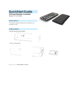
Local User Interface
The local setup interface consists of two buttons - LRN and
DIM - and a 2-color LED (green, red).
The two buttons can be used to link and unlink transmitters,
to dim up and down manually and to set the minimum
dimming value.
To use the local setup interface, hold the module so both
thumbs can click the buttons without obscuring the LED.
Remote Commissioning Interface
The LED controller provides a wireless remote
commissioning interface for all commissioning tasks.
This interface allows configuring all device parameters
wirelessly using a laptop computer equipped with Navigan
Wireless Commissioner (NWC 300U), consisting of a USB
stick and software.
Parameters that are configurable using the Navigan Wireless
Commissioner NWC 300U are marked in italic throughout
this document.

LED Zone Controller 0-10V Installation Guide
© 2017 EnOcean GmbH V2.0 Page 3
4.
Linking
Linking is the process by which different devices are
configured to work with each other in a system. Sometimes
this process is also called Teach-in or Learn-in.
The LED controller can work together with two types of
devices:
n Transmitters (switches and sensors) can provide input
data to the LED controller
n Transceivers (gateways or controllers) can exchange data
and commands with the LED controller
To link LED controller with a transmitter or transceiver, LED
controller must be powered, within wireless range of the
device it is to be linked to, and set to linking mode to accept
links.
Once these conditions are met, the link device is triggered
to send a special link message. LED Controller receives this
link message and stores the link parameters permanently so
that the two devices can interact to provide a variety of
intelligent control options.
Linking to transmitters (sensors or switches)
Transmitters are typically energy-harvesting devices that
send RF messages to communicate a condition, level, or
state.
The following wireless transmitter types can be linked to the
LED controller:
n Switches
n Occupancy Sensor
n Light Level Sensor
Transmitters can only be linked to transceivers (such as LED
controller), not to other transmitters (such as switches).
Transmitter link / unlink procedure
1.
Shortly press the LRN button to enter linking / unlinking
mode. The LRN LED starts toggling red / green indicating
that linking / unlinking mode is active. In addition, the
connected load will toggle between 0% and 100%.
Once activated, this mode stays temporary active to
provide time to link / unlink multiple devices. The mode
will stop after 30 seconds if no LRN telegram is received.
2.
For the transmitter to be linked, do one of the following
according to the type of device:
A.
Sensor: click the designated link button.
B.
Rocker Pad: click the “I” button (top button marked
on the switch plastic or “I” symbol on the back of the
switch) 3 times quickly.
3.
If the device has been linked successfully, the LRN LED
will display solid green for 4 seconds. The LED controller
is now ready to accept new links.
NOTE: After a device is linked, additional learn
telegrams received in operating mode (not in linking /
unlinking mode) from that device will cause the
connected load to toggle three times between 0% and
100%, if the EnableLinkChecker parameter is set to ON.
This allows quickly checking the connection between this
device and the LED Controller.
4.
For a linked transmitter to be unlinked, please use the
same action as described in point 2 above.
5.
If the device has been unlinked successfully then the LRN
LED will display solid red for 4 seconds and the load will
be switched to a dimming level of 10% for 4 seconds.
6.
To exit linking / unlinking mode and return to normal
operation, wait 30s without sending new LRN telegrams,
or shortly press the LRN button again.
Clear all linked transmitters
In order to clear all linked devices and reset the LED
controller to factory settings, please press and hold the LRN
button for 10 seconds. After that the LRN LED will display
solid red for 10 seconds.
Linking to Transceivers (gateways or controllers)
The LED controller is a transceiver.
Transceivers are controlling devices that send as well as
receive RF messages. They typically contain control logic and
might actuate appropriate outputs (switching a light ON or
OFF for example).
LED controller can be linked to other transceivers if desired.
The following other transceiver types are supported:
n Demand Response Controller
n Central Controller

LED Zone Controller 0-10V Installation Guide
© 2017 EnOcean GmbH V2.0 Page 4
Transceiver link / unlink procedure
1.
Set the other device into linking mode, then shortly press
the LRN button. The LRN LED starts toggling indicating
that linking / unlinking mode is active. The connected
load will toggle between 10% and 90%.
2.
Shortly press the DIM button. This will cause the LED
Controller to transmit a teach-in message identifying the
status message EEP used by it.
3.
Shortly press the LRN button again to return to normal
operation.
Setting the minimum output voltage level
It is possible to configure the minimum output voltage
(MinVoltageLevel) of the LED Controller via its button
interface. This level is typically set to avoid flickering and will
be the minimum level the load starts at when it is switched
on. It will not be possible to dim the output below this value.
Use the following steps to configure this minimum dimming
value:
1.
Press and hold the DIM button.
The load will start dimming up and down.
2.
Release the button when the desired minimum output
voltage (dimming value) is reached.
3.
Shortly press DIM and LRN button simultaneously to
store this value.
5.
Operating modes
The LED Controller supports the following operation modes
based on different types of connected devices:
Mode Default Action
Title 24
Compliance
Switches only
Manual DIM or ON/OFF
No
Occupancy
sensors only
Auto ON/ Auto OFF
(default Auto OFF after 15 minutes)
No
Occupancy
sensors and
switches
Manual DIM or ON, Auto OFF
Can be configured to Auto ON /
Auto OFF via remote
commissioning. (default Auto OFF
after 15 minutes)
Yes
Light level
sensor
Continuous dimming based on 5
supporting points or two level
(ON / OFF) dimming
Yes
Additional
central
controller
Dimming via central controller
overriding sensor and switch input
Yes
Additional
demand
response
controller
During a demand response event
output will be reduced to the
value specified in the command.
After the demand response
timeout the system will switch
back to the previous state.
Yes
6.
Functional behavior
0-10V Interface
The minimum output voltage is MinVoltageLevel (default
1.0V); the maximum output voltage is MaxVoltageLevel
(default 10.0V).
Dimming below MinVoltageLevel or above MaxVoltageLevel
is not possible.
Level and ramp percentage levels refer to the interval
between MinVoltageLevel (1%) and MaxVoltageLevel (100%).
An output level of 0% equals OFF state.

LED Zone Controller 0-10V Installation Guide
© 2017 EnOcean GmbH V2.0 Page 5
Switches only
Short click (<0.7s) on “I” button: Light comes ON and
brightens to most recent dimming value stored before
device was switched OFF.
If a light level sensor is linked, then light will be set
according to its input (see below). The minimum initial light
level in this case is MinVoltageLevel (default 1.0V).
Double click (<0.7s) on “I” button: Light is switched ON at
MaxVoltageLevel (default 10.0V).
Short click (<0.7s) or double click (<0.7s) on “0” button: The
current light level is stored, light is dimmed down to
MinVoltageLevel and then switched OFF.
Ramp up (RockerSwitchOnSpeed) and ramp down
(RockerSwitchOffSpeed) speeds for rocker switch operation
are configurable (default 20% per second).
Press and hold “I” / “0” button: Light is brightened / dimmed
until button is released or MinVoltageLevel /
MaxVoltageLevel is reached.
Ramp up (RockerDimUpSpeed) and ramp down
(RockerDimDownSpeed) speeds for rocker dim operation are
configurable (default 20% per second).
Rocker-based dimming can be disabled by setting
RockerDimEnable = OFF. In this case light will be switched
ON / OFF immediately upon pressing the “I” / “O” button.
Light can be switched OFF automatically in absence of a
linked occupancy sensor if no user (switch) action occurs
during a period defined by RockerSwitchAutoOffTimer.
This feature can be disabled by setting
RockerSwitchAutoOffTimer = 0. This feature is automatically
disabled if an occupancy sensor is present. In this case,
automatic switch OFF of the light will be performed based
on the input from the occupancy sensor as described below.
Occupancy Sensors only
If at least one sensor detects motion, light is switched ON -
Auto ON function. Light level is set to OccAutoOnLevel
(default 100%) if no light level sensor is linked.
Otherwise light level is set according to the natural light
level reported by the light level sensor as described below.
If none of the linked occupancy sensors reports motion for a
period defined by OccAutoOffTimer (default 15min) then
light is set to OccAutoOffLevel (default 0%) - Auto OFF
function.
Ramp up (SensorRampUpSpeed) speed for Auto ON and
ramp down (SensorRampDownSpeed) speed for Auto OFF
are configurable (default 20% per second).
Occupancy Sensors and Switches
Light can be switched ON / OFF manually, function as
described above. Time-based automatic switch OFF (as
defined by RockerSwitchAutoOffTimer) is always disabled if
at least one occupancy sensor is linked.
If no presence has been reported by any of the linked
occupancy sensors and no switch input has been received
during a period defined by OccAutoOffTimer (default 15min),
then light will be set to OccAutoOffLevel (default 0%).
Light will be automatically turned back ON at the last state if
occupancy is reported within the VacancyGraceTimer period
(default 45s) after such Auto OFF event even if the Auto ON
function is disabled.
The system can also be configured (OccAutoOn = TRUE) to
automatically switch ON the light as described above.
If the user has switched the light OFF (by a linked switch)
then it can be turned ON again by occupancy sensor input
only after OccAutoOnDelay (default 15 minutes).
Light Level Sensor
One light level sensor can be linked to enable open-loop
dimming for daylight harvesting. The system then adjusts
the output light level according to incoming natural light.
The light level sensor should therefore be placed at a
position facing the window or skylight where it is not or only
minimally influenced by light from the fixtures.
If a light level sensor is linked, the LED controller will by
default activate daylight harvesting with continuous open
loop dimming according to a user-defined dimming curve
based on 5 configurable supporting points.
Each of these 5 supporting points defines the output light
level (OUT1 … OUT5) to be set by the LED controller for a
given reported natural light level (LEV1 … LEV5).
For natural light levels below LEV1, output light level OUT1
is set. Likewise, for natural light levels above LEV5, output
light level OUT5 is set.
Linear interpolation is used between the defined points (e.g.
between LEV1/OUT1 and LEV2/OUT2).

LED Zone Controller 0-10V Installation Guide
© 2017 EnOcean GmbH V2.0 Page 6
Setting the output light level to 0 will cause the output of
LEDR to go to OFF state.
If the light level has been adjusted by the user (by single or
double click on the “I” button or by brightening / dimming
via “I” / “O” button), then the selected light level will be
maintained for a period defined by LlsAdjustmentDelay
(default 15 minutes).
After that, LEDR output is adjusted according to the light
level reported by the light level sensor.
In five point dimming mode, users can modify the dimming
curve if LlsEnableCurveAdjustment = ON.
This is achieved using a fast triple click (<0.7s) on the “I”
button. Doing so will replace the supporting point matching
most closely the current reported illumination level with the
current illumination level and the current 0-10V output level.
The connected light will blink (0% / 100%) three times to
acknowledge successful adjustment. Doing that at different
daylight levels allows defining the whole curve.
The light level sensor can alternatively be used to activate an
automatic switching mode between 0% (OFF) and 100%
(MaxVoltageLevel) based on light intensity (twilight switch).
This can be achieved by configuring DaylightingMode to
2-level mode via remote commissioning.
The thresholds for switching between the two levels are
defined by PhotoOnThres (output will be set to
MaxVoltageLevel for reported values below this level) and
PhotoOffThres (output will be set to MinVoltageLevel for
reported values above this level).
Repeater function
The LED controller provides the option to activate one-level
(repeat only original telegrams) or two-level (repeat original
telegrams or telegrams that were repeated once) repeater
mode for EnOcean radio telegrams.
By default (RepeatLinkedDevicesOnly=ON) only messages
from linked devices are repeated. Setting this parameter to 0
will cause all messages to be repeated.
Note: 2-level repeating function and repeating of all
messages (RepeatLinkedDevicesOnly=OFF) should only be
used if really needed! Otherwise the system function can be
compromised by collisions of telegrams.
Status messages
The LED controller will transmit a status message
(EEP D2-40-00) after change of its output state or after
StatusMessageTimer has elapsed.
By setting StatusMessageTimer to 0 status messages can be
switched off completely. By setting it to 0xFFFF only event
based messages will be sent.
Central controller
LEDR can also be connected to a central controller (EEP A5-
38-08). It supports the dimming command 0x02 of this EEP.
7.
Troubleshooting
Problem
Solution Checklist
The device does not power up
•
Check the wiring for errors
•
Check the circuit breaker
•
Use a voltage meter to confirm
power
Cannot link other devices
•
Check if linking mode can be
accessed
•
Move closer to the device; it
may be out of range
•
Try linking a different device
•
Check for environmental
conditions that interfere with
RF signals
•
Verify the maximum number of
devices has not been exceeded
- 20 switches
- 10 occupancy sensors
- 1 light level sensor
- 1 central controller
- 1 demand response controller
The device does not respond to
wireless messages or selected
settings
•
Check for environment or
range issues
•
Verify the device is linked
•
Check if appropriate devices
are linked according to good
system planning
•
Extend the antenna to amplify
the range: remove it from the
groove in the module, and
straighten it.
Contains: 902 MHz: FCC: SZV-STM300U
IC: 5713A-STM300U
This device complies with part 15 of the FCC rules and Industry Canada ICES-003.
Operation is subject to the following two conditions: (1) This device may not cause harmful
interference, and (2) this device must accept any interference received, including interference
that may cause undesired operation.
IMPORTANT! Any changes or modifications not expressly approved by the party responsible for
compliance could void the user’s authority to operate this equipment.

LED Zone Controller 0-10V Installation Guide
© 2017 EnOcean GmbH V2.0 Page 7
8.
Remote Commissioning Parameters
P
Parameter
Description
Default /
Notes
Light Level Sensor Parameters
DaylightingMode
2-level or 5 point continuous
daylight dimming
5 point
PhotoOnThres
In case of 2-level mode, light is
switched to Max
VoltageLevel if
light level is below PhotoOnThres
<200lux
PhotoOffThres
In case of 2-level mode, light is
switched to Min
VoltageLevel if
light level is above PhotoOffThres
>400lux
LEV1…5
Defines 5 input light levels for
open loop dimming
curve
(LEV1<LEV2<...<LEV5)
100, 200, 400,
600, 800 lux
OUT1…5
Defines the LED controller output
values for the corresponding
input
light levels
100, 100%, 60%,
20%, 0%
RAMP12, 23, 34,
45
Ramp speeds between light levels
1 and 2, 2 and 3, 3 and 4 , 4 and 5
1%/s
LlsAdjustment-
Delay
Time before the light level sensor
can adjust the output light level
after it was set by the user
15 min
LlsEnable-
CurveAdjustment
Enables or disables user
adjustment of the 5 point
dimming curve using triple click
on the “I” button
ON (enabled)
Generic Sensor Parameters (Occupancy and Light Level)
SensorRamp-
UpSpeed
Ramp-up speed when change is
triggered by an occupancy
or light
level sensor (2 point mode)
20%/s
0= No ramp
(immediate)
SensorRamp-
DownSpeed
Ramp-down speed when change
is triggered by an occupancy or
light level sensor (2 point mode)
20%/s
0= No ramp
(immediate)
Parameter Description
Default /
Notes
Rocker Switch Parameters
RockerSwitch-
On
Speed
Ramp-up speed when rocker
input request light switch ON
20%/s
0= No ramp
(immediate)
RockerSwitch-
Off
Speed
Ramp-down speed when rocker
input request light switch OFF
20%/s
0= No ramp
(immediate)
RockerDim-
Up
Speed
Ramp-up speed when rocker
input request light dim UP
20%/s
0= No ramp
(immediate)
RockerDim-
Down
Speed
Ramp-down speed when rocker
input request light dim DOWN
20%/s
0= No ramp
(immediate)
RockerSwitch-
AutoOffTimer
Delay after last switch action
before light is switched OFF
automatically
0 (disabled)
RockerDimEnable
Enables or disables dimming via
rocker switch
ON (enabled)
Occupancy Sensor Parameters
OccAutoOn
Defines if a signal from an
occupancy sensor automatically
switches on lights
(True/False)
FALSE if at least
one switch is
linked,
otherwise TRUE
OccAutoOnLevel
Dimming value at which light is
switched on in case of Auto ON
event from occupancy sensor
100%
OccAutoOnDelay
Time before the occupancy sensor
can switch the light back ON in
Auto ON Mode after the user
switched it OFF
15 min
OccAutoOffTimer
Time after which lights will be
switched to OccAutoOffLevel in
case of no motion
15 min
0=disabled
OccAutoOffLevel
Dimming value to which lights will
be dimmed after an occupancy
sensor Auto OFF timer event
0%
VacancyGrace-
Timer
If occupancy is detected within
the
VacancyGraceTimer period
after an occupancy A
uto OFF
event, lights are turned back
ON
45 s

LED Zone Controller 0-10V Installation Guide
© 2017 EnOcean GmbH V2.0 Page 8
P
Parameter
Description
Default /
Notes
System Parameters
MinVoltageLevel
Minimum 0-10V output voltage
level when light is switched ON
1.0V
MaxVoltageLevel
Maximum 0-10V output voltage
level when light is switched ON
10.0V
ModeAfter-
PowerLoss
ModeAfterPowerLoss
(ON/OFF/LAST STATE)
LAST STATE
StatusMessage-
Timer
Defines, how often status messages
are transmitted (seconds, 0=off,
0xFFFF=only event based)
0xFFFF
RepeaterFunction
Defines the repeater level of the
device (OFF/1-Level/2-Level)
OFF (disabled)
RepeatLinked-
DevicesOnly
Configures the repeater to only
repeat telegrams from devices
linked to it
ON (enabled)
Enable-
DebugMessages
Enable or disable debug messages
OFF (disabled)
EnableLink-
Checker
Enable or disable link checker
(if a learn telegram from a linked
device is received while in
operating mode, the 0-10V output
will toggle once between 10% and
90%)
ON (enabled)
/