Page is loading ...

XR150FC/XR550FC Series
DIGITAL MONITORING PRODUCTS, INC.
© 2021
INSTALLATION GUIDE


MODEL XR150FC/XR550FC SERIES PANEL
INSTALLATION GUIDE
FCC NOTICE
This equipment generates and uses radio frequency energy and, if not installed and used properly in strict accordance
with the manufacturer’s instructions, may cause interference with radio and television reception. It has been type tested
and found to comply with the limits for a Class A computing device in accordance with the specification in Subpart J
of Part15of FCC Rules, which are designed to provide reasonable protection against such interference in a residential
installation. If this equipment does cause interference to radio or television reception, which can be determined by
turning the equipment o and on, the installer is encouraged to try to correct the interference by one or more of the
following measures:
Reorient the receiving antenna
Relocate the computer with respect to the receiver
Move the computer away from the receiver
Plug the computer into a dierent outlet so that computer and receiver are on dierent branch circuits
If necessary, the installer should consult the dealer or an experienced radio/television technician for additional
suggestions. The installer may find the following booklet, prepared by the Federal Communications Commission, helpful:
“How to identify and Resolve Radio-TV Interference Problems.”
This booklet is available from the U. S. Government Printing Oce, Washington D. C. 20402
Stock No. 004-000-00345-4
© 2021Digital Monitoring Products, Inc.
Information furnished by DMP is believed to be accurate and reliable.
This information is subject to change without notice.

TABLE OF CONTENTS
About the Panel .....................................................................................................................1
Zone Expansion ........................................................................................................................................................................ 1
Output Expansion ....................................................................................................................................................................1
Compliance Instructions ........................................................................................................................................................1
Specifications Summary .......................................................................................................2
Power Supply .............................................................................................................................................................................2
Communication .........................................................................................................................................................................2
Panel Zones ................................................................................................................................................................................ 2
Keypad Bus .................................................................................................................................................................................2
LX-Bus .......................................................................................................................................................................................... 2
Outputs ........................................................................................................................................................................................ 2
System Components ..............................................................................................................3
Lightning Protection ...............................................................................................................................................................3
Network Surge Protection ....................................................................................................................................................3
Install the panel ......................................................................................................................4
Mount the Enclosure ............................................................................................................................................................... 4
Fire Command Center LCD Keypad .................................................................................................................................5
Mounting Additional Keypads, Zone Expanders, and Modules ............................................................................. 5
Wire the panel ........................................................................................................................ 6
Wiring Specifications..............................................................................................................................................................6
Wire the Transformer ..............................................................................................................................................................6
Wire the Batteries .................................................................................................................................................................... 7
Power Requirements ..............................................................................................................................................................8
Standby Battery Selection ...................................................................................................................................................10
LX-Bus Expansion .................................................................................................................................................................... 11
Wireless Bus Expansion .........................................................................................................................................................11
Ethernet Connection ..............................................................................................................................................................11
Phone Line RJ Connector ..................................................................................................................................................... 11
RESET and TAMPER Headers ............................................................................................................................................. 12
Bell Output .................................................................................................................................................................................13
Keypad Bus .................................................................................................................................................................................13
Smoke and Glassbreak Detector Output ........................................................................................................................13
Protection zones ......................................................................................................................................................................14
Powered Zones for2-Wire Smoke Detectors ...............................................................................................................15
Dry Contact Relay Outputs ..................................................................................................................................................15
Annunciator Outputs .............................................................................................................................................................. 16

Ordering Information ............................................................................................................17
Accessories .................................................................................................................................................................................17
FCC Information .....................................................................................................................21
Part15 ...........................................................................................................................................................................................21
Part68 ..........................................................................................................................................................................................21

XR150FC/XR550FC Series Installation Guide Digital Monitoring Products
1
ABOUT THE PANEL
The DMP XR150FC/XR550FC Series system consists of an alarm panel with a built-in communicator, an enclosure with
built-in Fire Command Center keypad, and a 16VAC 56VA transformer. Each panel is a versatile 12VDC, combined
access control, burglary, and fire communicator panel. A complete system can provide:
• 142 or 574 programmable inputs and outputs for commercial and industrial fire alarm service
• Eight onboard grounded burglary zones
• Two onboard 12VDC Class B powered zones
The powered zones have a reset capability to provide for2-wire smoke detectors, relays, or other latching devices.
Connect a12or24VDC regulated, power limited power supply listed for Fire Protective Signaling Systems to distribute
notification appliance power between Model865, 866or867NAC outputs. Addressable smoke detectors and input
modules round out the XR150FC/XR550FC Series panel to deliver a truly flexible and expansive fire detection and
notification system. The Fire Alarm Control Panel is shipped pre-wired in a red steel enclosure.
Zone Expansion
Up to574additional zones are available on the XR150FC/XR550FC Series panel using DMP LCD keypad remote zone
capability and zone expansion modules. The panel keypad data bus supports up to fifteen supervised device addresses
with each address supporting up to four programmable expansion zones.
Up to500zones are available using the on board LX-Bus connections, along with any combination of single, four, eight,
or sixteen-zone expansion modules and single-zone LX-Bus detectors.
Output Expansion
In addition to the two SPDT relays and four programmable open collector outputs on the panel, you can also connect up
to25programmable Model716Output Expansion Modules to each LX-Bus. These modules can provide an additional 100
or 500 programmable SPDT relays.
The panel provides100Output Schedules you can use for programming the716to perform a variety of annunciation and
control functions. You can also assign the716outputs to any panel Output Options such as Fire Alarm, Communication
Fail, or Phone Trouble Outputs. For more information, refer to the716Installation Guide (LT-0183).
The LX-Bus also supports the Model717Graphic Annunciator Module. Each717module supplies20switched ground
outputs that follow the state of their assigned zones. The717supports the first eight Keypad Bus addresses. To use
Keypad Bus addresses 9-16, install multiple716modules. Refer to the717Installation Guide (LT-0235) and716Installation
Guide (LT-0183).
Compliance Instructions
For applications that must conform to a local authorities installation standard or a National Recognized Testing
Laboratory certification standard, refer to the Compliance Listing Guide (LT-1330).

Digital Monitoring Products XR150FC/XR550FC Series Installation Guide
2
SPECIFICATIONS SUMMARY
For a full list of compatible panel accessories, refer to "Ordering Information".
Power Supply
Transformer Input—Primary input: 120VAC 60Hz; Primary Output: 16VAC56VA
Standby Battery—12VDC, 1.0Amps Max. charging current
Smoke and Auxiliary—12VDC output at 0.5Amp Max
Bell Output—12VDC at 0.7Amp Max
The combined Auxiliary and Bell outputs total cannot exceed1.2Amps with a56VA transformer. All circuits are power
limited except the red battery wire and AC terminal.
Communication
• Built-in network communication to SCS-1R and SCS-VR Receivers
• Built-in dialer communication to SCS-1R Receivers
• Optional cellular communication to SCS-1R and SCS-VR Receivers
• Built-in Contact ID communication to SCS-1R Receivers
• Optional893A Dual Phone Line Module with phone line supervision
• Can operate as a local panel
Panel Zones
Eight1k or 2.2k Ohm EOL burglary zones (1-8) and two3.3k Ohm EOL powered zones with reset (9-10). To select either
1k or 2.2k for zones 1 to 8, program the EOL value in REMOTE OPTIONS.
Keypad Bus
You can connect the following supervised keypads and expansion modules to the Keypad Bus:
• Alphanumeric keypads
• Sixteen, eight, four, and single-zone expansion modules
• Single zone detectors
• Access control modules
LX-Bus
You can connect the following devices to the LX-Bus connections provided on the panel. See Accessory Devices for
information about specific connections.
• Graphic annunciator modules
• Sixteen, eight, four, and single-zone expansion modules
• Relay output expansion modules
• Smoke Detectors
Outputs
The XR150FC/XR550FC Series panel provides two Single Pole, Double Throw (SPDT) relay outputs which require
the installation of two Model305relays, each rated1Amp at30VDC resistive (power limited sources only). A
Model431Output Harness is required to use these outputs.
The panel also provides four open collector outputs rated for50mA each. The open collector outputs provide ground
connection for a positive voltage source. A Model300Output Harness is required to use these outputs.

XR150FC/XR550FC Series Installation Guide Digital Monitoring Products
3
SYSTEM COMPONENTS
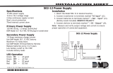
Figure 1 shows some of the accessory modules you can connect for use in various applications. A brief description of
each module follows in the Accessory Devices section.
Lightning Protection
Metal Oxide Varistors and Transient Voltage Suppressors help protect against voltage surges on panel input and output
circuits. Additional surge protection is available with Model370or370RJ Lightning Suppressors. For more information,
refer to the 370/370RJ Installation Sheet (LT-0181).
Network Surge Protection
The Model270Network Transient Suppression Module protects the panel from surges on the Ethernet port. For more
information, refer to the Model 270 Installation Guide (LT-1316).
Figure 1:XR150FC/XR550FC Series Wiring Diagram
XR550FC Series
Panel
s ss ss s
Rear
Tamper
Front
Tamper
s
= Supervised Circuit
RED
RED
RED
YELLOW
GREEN
BLACK
RED
YELLOW
GREEN
BLACK
RED
BLACK
1.5k Ω
AC Wiring must be in conduit and exit out
the left side of the enclosure.
Wiring on terminals 5 through 22 must
exit right and maintain 1/4" separation
from the AC and battery positive wiring.
PHONE LINE
RESET
TAMPER
Battery
Start
Power
LED
Activity
LED
(Yellow)
ETHERNET
OUTPUTS 3-6
OUTPUT 2
OUTPUT 1
OUT1 OUT2
Link
LED
(Green)
CELL
MODULE
LOAD
PROG
LX
DMP Transformer
16 VAC 56 VA
Class 2 Wire-in
Secondary Power
Supply
1.0 Amps Max. charging
current. Use only 12 VDC
rechargeable batteries.
DMP Models 364, 365,
366, 368, or 369. Replace
batteries every 3 to 5
years.
Bell
12 VDC nominal
Minimum cuto time is
5 minutes.
0.7 Amp Max
Keypads
Model 630F
60 mA at 8 to 14.5 VDC
All circuits are inherently
Power Limited except the red
battery wire and AC terminal.
NFPA 72
This equipment should be
installed in accordance with
Chapter 11 of the National Fire
Alarm Code, ANSI/NFPA
72-2002, (National Fire
Protection Association,
Batterymarch Park, Quincy,
MA 02269). Printed
information describing proper
installation, operation, testing,
maintenance, evacuation
planning, and repair service is
to be provided with this
equipment.
Use UL Listed
Power Supervision
Relay rated at
12 VDC.
WARNING: Incorrect
connections may cause
damage to the unit.
CAUTION: DO NOT USE LOOPED WIRE
UNDER TERMINALS. BREAK WIRE RUN
TO PROVIDE SUPERVISION OF
CONNECTIONS.
Earth Ground
Zone Expander
Model 715
7 mA @ 12 VDC
Models 715-8, 715-16
20 mA @ 12 VDC
Zone
Expander (up
to 8 zones)
Model 712-8
19 mA @
12 VDC
Zone
Expander
Model 711
7 mA @
12 VDC
Zone Expander
Model 714
7 mA @ 12 VDC
Models 714-8, 714-16
20 mA @ 12 VDC
Auxiliary Power
Total current combined from
Terminals 7, 11, 25, 27, and
LX500-LX900
0.5 Amp Max
Listed Resistors
1.0k Ohm—DMP Model 311
3.3k Ohm—DMP Model 309
10K Ohm—DMP Model 308
Form C Relays (OUT 1 and OUT 2)
Output Color Code–Model 431
Harness
Output 2 N/O Orange/White
Output 2 Com White/Gray
Output 2 N/C Violet/White
Output 1 N/O Orange
Output 1 Com Gray
Output 1 N/C Violet
Annunciator Outputs (OUTPUTS 3-6)
Output Color Code
Output 3 Red
Output 4 Yellow
Output 5 Green
Output 6 Black
s s s s
ssssssssssssssss
s
sss
ss
s
s
s
s
s
s
s
ss ss ss ss ss
s s
POWER
TROUBLE
ALARM
COMMAND
12 34
5678
90
ABC DEF GHI JKL
MNOPQR STUVWX
YX
ENABLE
SILENCE
RESET
TEST
DRILL
Fire Command Center
AC
1 2 3 4 5 6 7 8 10 11 12 13 14 15 16 17 18 199 20 21 22 23 25 26 27 28
+B BELL GND SMK GNDRED YEL GRN BLK Z1 Z2 Z3 Z4 Z5 Z6 Z7
24
Z8 Z9+ Z9– Z10+ Z10–AC –B GND GND GNDGND
Bell cuto time
range is 5 to 99
minutes marchtime
and non-coded.
ss
1/4"
AC
1 2 3 4 5 6 7 8 10 11 12 139
+B BELL GND SMK GNDRED YEL GRN BLK Z1AC –B
Heat detectors, pull
stations, or any other
contact devices listed
for Fire Protective
Signaling can be
connected to zones 9
and 10.
Zones 9 and 10 and
Model 715 compatibility
identifier: A
Maximum operating
range: 9.8 VDC to
14.0 VDC.
Class B (Style A).
Zones 9, 10, and all
expanded zones are
suitable for Class B (as
applicable for the
initiating and signaling
line circuits per
ANSI/UL 864 Table
48.2 or 48.3).
Installation limits under
local Authority Having
Jurisdiction (AHJ).
Using verification
delays on zones 9 and
10 is optional. Use the
delays marked on the
smoke detectors or the
smoke detector
installation wiring
diagram.
Verification
Zones
______
Control Unit
Delay
13.6 sec
Smoke
Model
______
Detector
Delay
____sec
WARNING
THIS UNIT MAY BE PROGRAMMED TO USE AN ALARM
VERIFICATION FEATURE THAT RESULTS IN DELAY OF THE
SYSTEM ALARM SIGNAL FROM THE INDICATED CIRCUITS. THE
TOTAL DELAY (CONTROL UNIT PLUS SMOKE DETECTORS)
SHALL NOT EXCEED 60 SECONDS. NO OTHER SMOKE
DETECTOR SHALL BE CONNECTED TO THESE CIRCUITS
UNLESS APPROVED BY THE LOCAL AUTHORITY HAVING
JURISDICTION (AHJ).

Digital Monitoring Products XR150FC/XR550FC Series Installation Guide
4
INSTALL THE PANEL
Mount the Enclosure
The XR150FC/XR550FC Series panel enclosure must be mounted using the four mounting holes shown in Figure 2.
Mount the enclosure in a secure, dry place to protect the panel from damage from tampering or the elements. It is not
necessary to remove the panel PCB when installing the enclosure.
The enclosure dimensions are13.44” H X17.1” W X4.8” D.
Note When using the XRFCXRFC Series panel for listed applications use the Model orS
enclosure for standby batteries
Battery shelf holds up to two batteries. Maintain
minimum spacing of 1/4” between the batteries
and any modules mounted in enclosure.
A
B
C
Panel
Transformer
Enclosure Mounting Holes
D
E
Dual 1-3/4” and 1-3/8” Knockouts
Module Mounting Holes
FBattery Shelf
E
E
E
DD
C C
C C
A
F
B
Figure 2:XR150FC/XR550FC Enclosure

XR150FC/XR550FC Series Installation Guide Digital Monitoring Products
5
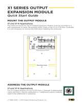
Fire Command Center LCD Keypad
A Fire Command Center LCD Keyboard is factory installed on the panel enclosure door. The installed, pre-wired
keyswitch is located to the left of the keyboard. The user can turn the keyswitch to enable the four function keys without
opening the enclosure door. The display and keyboard are factory pre-wired to the PROG header. For standby battery
calculations, the LCD display draws92mA of current in normal, standby, or alarm condition. For more information, refer
to "Power Requirements".
Mounting Additional Keypads, Zone Expanders, and Modules
DMP keypads have removable covers that allow you to easily mount the keypad to a wall or other flat surface using the
screw holes on each corner of the base. Before mounting the base, connect the keypad wire harness leads to the panel
and to any applicable devices. Then, attach the harness to the pin connector to the PCB, mount the base, and install the
keypad cover making sure all of the keys extend through their respective holes.
For mounting additional keypads on solid walls, or for applications where conduit is required, use the Model695 1-1/2”
deep backbox or the Model696 1/2” deep backbox.
The DMP711, 712-8, 714, 715, 716, and717zone expanders are each contained in molded plastic housings with removable
covers. The base provides you with mounting holes for installing the unit to a wall, switch plate, or other surface.
Mount any additional modules in the panel enclosure using the standard 3-hole mounting pattern. Refer to the
appropriate product guides for installation instructions.
ALARM
TROUBLE
POWER
COMMAND
1 2 3 4
5 6 7 8
9 0
ABC DEF GHI JKL
MNO PQR STU VWX
YX
ENABLE
SILENCE
RESET
TEST
DRILL
Fire Command Center
Figure 3:Fire Command Center LCD and Keypad

Digital Monitoring Products XR150FC/XR550FC Series Installation Guide
6
WIRE THE PANEL
Wiring Specifications
DMP recommends using 18 or 22 AWG for all LX-Bus and Keypad Bus connections. The maximum wire distance between
any module and the DMP Keypad Bus or LX-Bus circuit is 1,000 feet. To increase the wiring distance, install an auxiliary
power supply, such as a DMP Model 505-12. Maximum voltage drop between a panel or auxiliary power supply and any
device is 2.0 VDC. If the voltage at any device is less than the required level, add an auxiliary power supply at the end of
the circuit.
To maintain auxiliary power integrity when using 22-gauge wire on Keypad Bus circuits, do not exceed 500 feet. When
using 18-gauge wire, do not exceed 1,000 feet. Maximum distance for any bus circuit is 2,500 feet regardless of wire
gauge. Each 2,500 foot bus circuit supports a maximum of 40 LX-Bus devices. To increase the wire length or to add
devices, install an additional power supply that is listed for Fire Protective Signaling, power limited, and regulated
(12VDC nominal) with battery backup.
For additional information refer to the LX-Bus/Keypad Bus Wiring Application Note (LT-2031) and the 710 Bus Splitter/
Repeater Module Installation Guide (LT-0310).
Wire the Transformer
The XR150FC/XR550FC Series panel comes with a16VAC56VA transformer. The16VAC transformer must be wired to
a dedicated, unswitched120VAC60Hz circuit with at least 0.87Amps available.
Caution Never share the Fire Alarm Control Panel circuit with any other equipment. Always ground the panel before
applying power to any devices and use AWG or larger for all power connections
56 VA
Transformer
The transformer
must be wired to a
dedicated,
unswitched
120 VAC 60 Hz
circuit with at least
0.87A available
GND
Install cover over screw
terminals after
completing connection.
WHITE
BLACK
GREEN/
YELLOW
S
AC
1 2 3 4
+BAC –B
Figure 4:Transformer Wiring

XR150FC/XR550FC Series Installation Guide Digital Monitoring Products
7
Wire the Batteries
DMP recommends replacing batteries every3to5years under normal use. Connect the black battery lead to the
negative battery terminal. The negative terminal connects to the enclosure ground internally through the panel PCB.
Connect the red battery lead to the battery positive terminal. You can add a second battery in parallel using the DMP
Model318Dual Battery Harness. Refer to Figure for wiring information
Note DMP requires that wiring in a battery harness is separated by a PTC to protect batteries from a reversal or
short within the circuit
For listed installations, batteries can be installed in a DMP Model341, 349, 350or352S enclosure and all wiring shall
run through conduit. The enclosure shall be installed to the left of the panel enclosure to ensure Battery and AC wire
separation.
Caution Use sealed lead-acid batteries only. Batteries supplied by DMP have been tested to ensure proper charging
with DMP products. Do not use gel cell batteries.
Earth Ground (GND)
To provide proper transient suppression, panel Terminal4(battery negative) must be connected to an earth ground
using wire 14-gauge or larger.
DMP recommends connecting to a cold water pipe, ground rod, or building ground only. Do not connect to an electrical
ground or conduit, sprinkler or gas pipes, or to a telephone company ground.
Battery Only Restart
When powering up the XR150FC/XR550FC
Series panel without AC power, briefly
short the battery start pads to pull in the
battery cuto relay. Once the relay has been
pulled in, the battery voltage holds it in that
condition.
If the panel is powered up with an AC
transformer, the battery cuto relay is pulled
in automatically. For more information refer
to Figure 1.
Discharge/Recharge
The XR150FC/XR550FC Series panel battery
charging circuit float charges at13.9VDC at a
maximum current of1.0Amps using a56VA
transformer. Battery voltage level conditions
are determined by the following voltage
ranges:
• Battery Trouble—Below11.9VDC
• Battery Cuto—Below10.2VDC
• Battery Restored —Above12.6VDC
Battery Supervision
The panel tests the battery when AC power is present. The test is done every three minutes and lasts for five seconds.
During the test, the panel places a load on the battery. If the battery voltage falls below11.9VDC a low battery is
detected. If AC power is not present, a low battery is detected any time the battery voltage falls below11.9VDC. When
battery voltage drops below10.2VDC, the panel performs a battery cuto to prevent deep discharge damage.
If a low battery is detected with AC power present, the test repeats every two minutes until the battery charges
above12.6VDC. If a weak battery is replaced with a fully charged battery, the restored battery will not be detected until
the next test is completed.
AC
1 2 3 4
+BAC –B
Battery
Start
Red
Black
Battery Battery
Battery
318 Battery
Harness
Red
Black
5 6
BELLGND
To AC
XR550
Panel
PTC
PTC
To Bell
Circuit
To Earth
Ground
Figure 5:Wiring Multiple Batteries

Digital Monitoring Products XR150FC/XR550FC Series Installation Guide
8
Power Requirements
During AC power failure, the panel and all connected auxiliary devices draw their power from the battery. All devices
must be taken into consideration when calculating the battery standby capacity. Use Table 1 to determine your system's
total required amp-hours, then proceed to Standby Battery Selection.
Standby Battery Power Calculations Standby Current Alarm Current
2W-BLX, 2WT-BLX Smoke Detectors Qty x 11mA = mA Qty x 31mA1= mA
263LTE Cellular Communicator Qty x 20mA = mA Qty x 20mA = mA
277Buzzer Module Qty x 5mA = mA Qty x 5mA = mA
630F Remote Fire Command Center Qty x 63mA = mA Qty x 92mA = mA
710Bus Splitter/Repeater Module Qty x 32mA = mA Qty x 32mA = mA
711Zone Expansion Module
Active Zone (EOL Installed)
Qty
Qty
x
x
11mA
1.6mA
= mA
= mA
Qty
Qty
x
x
11mA
2mA1
= mA
= mA
711SZone Expansion Module Qty x 4.2mA = mA Qty x 4.7mA = mA
712-8Zone Expansion Module
Active Zones (EOL Installed)
Qty
Qty
x
x
17mA
1.6mA
= mA
= mA
Qty
Qty
x
x
17mA
2mA1
= mA
= mA
714Zone Expansion Module
Active Zones (EOL Installed)
Qty
Qty
x
x
7mA
1.6mA
= mA
= mA
Qty
Qty
x
x
7mA
2mA1
= mA
= mA
714-8, 714-16Zone Expansion Module
Active Zones (EOL Installed)
Qty
Qty
x
x
20mA
1.6mA
= mA
= mA
Qty
Qty
x
x
20mA
2mA1
= mA
= mA
715Zone Expansion Module
Active Zones (EOL Installed)
2-Wire Smokes
Qty
Qty
Qty
x
x
x
7mA
4mA
0.1mA
= mA
= mA
= mA
Qty
Qty
Qty
x
x
x
7mA
30mA1
0.1mA
= mA
= mA
= mA
715-8, 715-16Zone Expansion Modules
Active Zones (EOL Installed)
2-Wire Smokes
Qty
Qty
Qty
x
x
x
20mA
4mA
0.1mA
= mA
= mA
= mA
Qty
Qty
Qty
x
x
x
20mA
30mA1
0.1mA
= mA
= mA
= mA
716Output Expansion Module
Active Form C Relays
Qty x 13mA = mA Qty
Qty
x
x
13mA
12mA
= mA
= mA
717Graphic Annunciator Module
Annunciator Outputs
Qty x 10mA = mA Qty
Qty
x
x
10mA
1mA
= mA
= mA
734Wiegand Interface Module
Active Zones (EOL Installed)
Annunciator (ON)
Proximity Reader
Qty
Qty
Qty
x
x
x
240mA
1.6mA
200mA
= mA
= mA
= mA
Qty
Qty
Qty
Qty
x
x
x
x
260mA
2mA1
20mA
200mA
= mA
= mA
= mA
= mA
736P POPIT Interface Module Qty x 25mA = mA Qty x 25mA = mA
736V V-Plex Module
Active Zones
Qty x 45mA = mA
= mA
Qty x 45mA = mA
= mA
738A Ademco Wireless Interface Module Qty x 75mA = mA Qty x 75mA = mA
738T Wireless Translator Qty x 50mA = mA Qty x 50mA = mA
738Zplus Z-Wave Interface Module Qty x 40mA = mA Qty x 40mA = mA
763 Wi-Fi Module Qty x 31mA = mA Qty x 31mA = mA
860Relay Output Module, one relay active
All four relays active
Qty x 34mA
138mA
= mA
= mA
Qty x 34mA
138mA
= mA
= mA
865Style Y or Z Notification Module Qty x 26mA = mA Qty x 85mA = mA
Subtotal currents Subtotal standby = mA Subtotal alarm = mA
1 Based on10% of active zones in alarm.
2 For systems that are not central station monitored, multiply alarm current by12.
Table 1: Standby Battery Power Calculations

XR150FC/XR550FC Series Installation Guide Digital Monitoring Products
9
Standby Battery Power Calculations Standby Current Alarm Current
866Style W Notification Module Qty x 45mA = mA Qty x 76mA = mA
867LX-Bus Style W Notification Module Qty x 30mA = mA Qty x 86mA = mA
869Dual Style D Initiating Module Qty x 25mA = mA Qty x 75mA = mA
893A Dual Phone Line Module Qty x 12mA = mA Qty x 50mA = mA
1100X Wireless Receiver Qty x 46mA = mA Qty x 46mA = mA
1100XH Wireless High Power Receiver Qty x 160mA = mA Qty x 160mA = mA
7060/7160Thinline/7060A Aqualite Keypad Qty x 72mA = mA Qty x 80mA = mA
7063/7163Thinline/7063A Aqualite Keypad Qty x 85mA = mA Qty x 100mA = mA
7070/7170Thinline/7070A Aqualite Keypad
Active Zones (EOL Installed)
Qty
Qty
x
x
72mA
1.6mA
= mA
= mA
Qty
Qty
x
x
87mA
2mA1
= mA
= mA
7073/7173Thinline/7073A Aqualite Keypad
Active Zones (EOL Installed)
Qty
Qty
x
x
85mA
1.6mA
= mA
= mA
Qty
Qty
x
x
100mA
2mA1
= mA
= mA
7872Graphic Touchscreen Keypad
Active Zones (EOL Installed)
Qty
Qty
x
x
145mA
1.6mA
= mA
= mA
Qty
Qty
x
x
215mA
2mA1
= mA
= mA
7873Graphic Touchscreen Keypad
Active Zones (EOL Installed)
Qty
Qty
x
x
143mA
1.6mA
= mA
= mA
Qty
Qty
x
x
243mA
2mA1
= mA
= mA
XR150FC/XR550FC Series Control Panel
Relay Outputs1-2 (ON)
Switch Grounds3-6 (ON)
Active Zones1-8
Active Zones9-10
2-Wire Smoke Detectors
Panel Bell Output (max 1500 mA)
Aux. power devices on Terminals 7 and
11 except keypads and LX-Bus modules
Qty 1
Qty
Qty
Qty
Qty
Qty
x
x
x
x
x
x
174mA
30mA
5mA
1.6mA
4mA
0.1mA
= 174 mA
= mA
= mA
= mA
= mA
= mA
= mA
Qty 1
Qty
Qty
Qty
Qty
Qty
x
x
x
x
x
x
217mA
30mA
5mA
2mA1
30mA
0.1mA
= 217 mA
= mA
= mA
= mA
= mA
= mA
= mA
= mA
Subtotal currents this page Subtotal standby = mA Subtotal alarm = mA
Subtotal currents previous page Subtotal standby + mA Subtotal alarm + mA
Total currents Total standby current = mA Total alarm current = mA
Total required standby current hours Required standby hours
x mA Total standby current
= mAh Total required standby current
Total required alarm current minutes Required Minimum alarm time
÷ 60 minutes Convert to hours
= hours Total required alarm time
x mA Total alarm current
= mAh Total required alarm current
Calculate total required amp-hours
mAh Total required standby current
+ mAh Total required alarm current
= mAh Total required milliamp-hours
+ mAh Percentage of total required mAh (optional)
= mAh Total required milliamp-hours (optional)
÷ 1000 h Convert mAh to Ah
= Ah Total required amp-hours (round up to whole number)
1 Based on10% of active zones in alarm.
2 For systems that are not central station monitored, multiply alarm current by12.
Table 1: Standby Battery Power Calculations

Digital Monitoring Products XR150FC/XR550FC Series Installation Guide
10
Standby Battery Selection
After performing the calculations in Power Requirements, complete the following steps to select standby batteries:
Note If the Power Requirements calculation is greater than any Max Ah Available shown on a table add power
supplies to reduce the required amp hours See theBus SplitterRepeater Installation Guide (LT-) for more
information
1. Select the desired standby hours required from the following table: 24, 60, or72hours.
2. Select the desired battery size, then select a Max. Ah Available that slightly exceeds the number of total required
Ah calculated in Power Requirements.
3. Install the number of batteries shown in the corresponding No. of Batteries column.
Example: If total required amp hours equals22Ah for24hours of standby time and you want to use5.0Ah batteries,
install six Model368 (12VDC, 5.0Ah) batteries.
For listed installations, batteries can be installed in a DMP Model341, 349, 350or352S enclosure and all wiring shall run
through conduit. The enclosure shall be installed to the left of the XR150FC/XR550FC Series panel enclosure to ensure
Battery and AC wire separation. For a list of compatible batteries, refer to "Batteries and Battery Accessories".
24hours standby power, 48 hours recharge time
5.0Ah Batteries 7Ah Batteries 7.7Ah Batteries 9Ah Batteries 18Ah Batteries
Max. Ah
Available
No. of
Batteries
Max. Ah
Available
No. of
Batteries
Max. Ah
Available
No. of
Batteries
Max. Ah
Available
No. of
Batteries
Max. Ah
Available
No. of
Batteries
8 2 6 1 6 1 8 1 16 1
12 3 12 2 13 2 16 2 32 2
16 4 18 3 20 3 24 3 48 3
20 5 24 427 4 32 4
24 6 31 5 34 5 40 5
28 7 37 641 6
32 8 43 7
36 9
40 10
60hours standby power, 48 hours recharge time
7Ah Batteries 7.7Ah Batteries 9Ah Batteries 18Ah Batteries
Max. Ah
Available
No. of
Batteries
Max. Ah
Available
No. of
Batteries
Max. Ah
Available
No. of
Batteries
Max. Ah
Available
No. of
Batteries
13 2 14 2 17 2 17 1
20 3 22 3 26 3 34 2
27 4 29 4 34 4 52 3
33 5 37 5 43 5 69 4
40 6 44 6 52 6
47 752 761 7
54 8 59 869 8
60 9 67 9
67 10
hours standby power hours recharge time
9Ah Batteries 18Ah Batteries
Max. Ah
Available
No. of
Batteries
Max. Ah
Available
No. of
Batteries
16 2 16 1
25 3 33 2
33 4 50 3
42 5 67 4
50 6
59 7
67 8
Table 1:Standby Battery Specifications

XR150FC/XR550FC Series Installation Guide Digital Monitoring Products
11
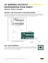
LX-Bus Expansion
There are five LX-Bus headers near the bottom of the panel:
• LX500 provides zones500-599 (XR150FC/XR550FC)
• LX600 provides zones600-699 (XR550FC only)
• LX700 provides zones700-799 (XR550FC only)
• LX800 provides zones800-899 (XR550FC only)
• LX900 provides zones900-999 (XR550FC only)
Wireless Bus Expansion
The Wireless Bus (XBUS) header provides connection for the1100X or1100XH Wireless Receiver. The XBUS provides up
to500wireless zones numbered500-999. Refer to the1100X Wireless Receiver Install Guide (LT-0708) or the1100XH
Wireless Receiver Install Guide (LT-0970) for complete information.
• XR150FCprovides up to100zones.
• XR550FCprovides up to500zones.
Wireless Bus LEDs
The two LEDs, located above the XBUS header, indicate data transmission and receipt. The left LED flashes green to
indicate the panel is transmitting data. The right LED flashes yellow to indicate the panel is receiving data.
Ethernet Connection
Description
The ETHERNET connector on the XR150FC/XR550FC Series panel allows you to connect
directly to an Ethernet network using a standard Cat 5 cable. The ETHERNET connector
supports100Mbps full duplex operation and the maximum impedance is100Ohms.
Ethernet LEDs
The two LEDs located on the top edge of the connector indicate network connection. The right
Link LED (green) lights to indicate a valid receive connection from the host network. The Activity
LED (yellow) lights when connected to a 100 Mbps network and is o when connected to a 10
Mbps network connection.
Network Transient Suppression
For listed fire applications, use a Model270Network Transient Suppression Module to provide
transient surge protection for the ETHERNET connector.
Phone Line RJ Connector
Connect the panel to the public telephone network by installing a DMP356RJ Cable between the panel PHONE LINE
connector and the RJ31X or RJ38X phone block. The maximum impedance is100Ohms.
Caution: To reduce the risk of fire, only use 26AWGor higher telecommunication line cord, such as a DMP
Model356Series Phone Cord.
893A OR277Connector
Allows connection of an893A Dual Phone Line Module or a277Trouble Sounder to the893A OR277connector on the
panel. Refer to the893A Installation Sheet (LT-0135) or the277Installation Sheet (LT-1304) for complete information.
Figure 6:LX-Bus Headers and LEDs
PROG
LX500
LX600
LX700
LX800
LX900
10
BLK
11
SMK
12
GND
13
Z1
14
GND
15
Z2
16
Z3
17
GND
18
Z4
19
Z5
20
GND
22
Z7
21
Z6
RED BLK RED BLK RED BLK RED BLK RED
J17
BLK
XMIT RCV
RED BLK
XMIT RCV
J8 J14 J9
XMIT
RCV
XMIT
RCV
XMIT
RCV
XMIT
RCV
PROG 500 600 700
Figure 7:Ethernet
Connector and LEDs
ETHERNET
Activity LED
(Yellow)
Link LED
(Green)

Digital Monitoring Products XR150FC/XR550FC Series Installation Guide
12
Notification
The user must not repair registered terminal equipment. In case of trouble,
immediately unplug the device from the telephone jack. Registered
terminal equipment may not be used on a shared or public line. Provide
the telephone company the following information:
• The particular lines where the service is connected
• The FCC registration number as listed
• The ringer equivalence
• The device make, model, and serial number
Phone Line Monitor
The XR150FC/XR550FC Series panel has a built-in telephone monitor that
monitors the phone line voltage to verify the connection to the central
station. Figure 8and Table 2 identify the phone block pin layout, wire
numbers, and colors.
The wires on the RJ31that feed pins4and5should be the only
wires on the DMARC. All other house phone wiring should be tied to
pins1and8coming back from the RJ31.
Dial tone must come in to RJ31X on pins4and5and go back to house
phones from pins1and8. Follow these steps to determine if the panel is
seizing the line:
1. Unplug phone cord from RJ31X
2. Place a butt-set on pins4and5
3. Confirm the presence of a dial tone, then lift the wire from either pins1or8.
4. If a dial tone is still present, the RJ31X wiring is correct. If no dial tone is present, the RJ31X wiring is backwards.
Rewire the phone block so the dial tone is coming in onpins 4and5, then retest the connection.
If you still have trouble with the phone line after rewiring the phone block, you may need to replace the RJ cord. If the
dial tone is still not present after replacing the phone cord, replace the RJ31X phone block.
RESET and TAMPER Headers
RESET Header
The RESET header is used to reset the panel. To reset the panel when installing the
system, place the jumper across both RESET pins before applying power to the
panel. After connecting the AC and battery, remove the reset jumper.
To reset the panel while the system is operational, install the reset jumper without
powering down the system. Remove the reset jumper after one or two seconds.
After resetting the panel, begin programming within30minutes. Otherwise, you
must reset the panel again to enter the PROG menu.
TAMPER Header
The TAMPER header is designed to connect to a tamper switch with a tamper
harness. One or more tamper switches can be mounted inside the panel enclosure
to supervise unauthorized removal or opening of an enclosure. Refer to the wiring
diagram on the enclosure door for correct tamper switch wiring.
If the enclosure is opened or removed while one or more of the system areas are
armed, the system goes into alarm. If all areas are disarmed, a tamper trouble is
indicated by the panel.
To Telephone
Line
RJ31X or RJ38X
Phone Block
8
7
6
54
3
2
1
Ring Tip
To Premise
Phone
Ring 1Tip 1
Figure 8:Phone Jack Wiring
Wire Number Wire Color
1Gray
2 Orange
3 Black
4Red
5 Green
6 Yellow
7 Blue
8 Brown
Table 2:Phone Jack Wiring
Figure 9:XR550FC Series Panel
Showing the RESET Jumper
Momentarily place the Reset
jumper over both of the J16
pins to reset the panel.
J6
J23
CELL MODULE
LOAD
RESET
LX800
LX900
LLX

XR150FC/XR550FC Series Installation Guide Digital Monitoring Products
13
Bell Output
Terminals5and6
Supplies positive12VDC to power alarm bells or horns. This output can be steady, pulsed, or temporal, depending on
the Bell Action specified in Bell Options. Terminal6is the ground reference for the bell circuit. This supervised output
reads resistance of1kOhms or less as normal. The indicating appliance can supply this resistance. If using a horn or siren,
install the included1kOhm0.5W resistor across the bell circuit to provide supervision. See the Notification Appliance
section in the Compliance Listing Guide (LT-1330) for wiring diagrams and a list of approved notification appliances.
Keypad Bus
Description
The panel Keypad Bus includes Terminals7, 8, 9, and10. You can connect up to fifteen supervised keypads and multiple
unsupervised keypads to the panel. In addition to DMP keypads, you can also connect any combination of zone
expansion modules. Refer to the specific device installation sheet for the maximum number of Keypad Bus devices. Refer
to the LX-Bus section for more information about LX-Bus expansion.
Terminal7 - RED
Supplies positive and regulated12VDC to power DMP LCD keypads and zone expansion modules. Terminal7also
supplies power for any auxiliary device. The ground reference for Terminal7is Terminal10.
The output current is shared with the smoke power output on Terminal11and zones9and10. Current draw for all
connected devices must not exceed the panel maximum current rating. See Power Supply in the Compliance Listing
Guide (LT-1330) for maximum current in a fire listed application.
Terminal8 - YELLOW
Receives data from keypads and zone expansion modules. It cannot be used for any other purpose.
Terminal9 - GREEN
Transmits data to keypads and zone expansion modules. It cannot be used for any other purpose.
Terminal10 - BLACK
The ground reference for DMP keypads, zone expansion modules, and all auxiliary devices being powered by Terminal7.
Programming (PROG) Connection
A4-pin PROG header is provided to connect a keypad when using a DMP Model330Programming Cable. This provides
a quick connection for panel programming. You may also use the PROG Header to connect Keypad Bus devices.
OVC LEDs
The Overcurrent LED (OVC) lights red when the devices connected to the Keypad Bus and LX-Bus draw current that
exceeds the panel rating. The OVC LED is located to the left of the893A connector on the panels.
XR150FC/XR550FC Series panels have an additional OVC LED to the right of the CELL MODULE connector. The LEDs
turn a steady red when lit. When the OVC LEDs light red, the LX-Buses and Keypad Bus are shut down.
Smoke and Glassbreak Detector Output
Terminals11and12
Supplies positive and regulated12VDC to power4-wire smoke detectors and other powered devices. This output can
be turned o by the user for5seconds using the Sensor Reset User Menu option to allow latched devices to reset.
Terminal12is the ground reference for Terminal11.
Current Rating
The Output current from Terminal11is shared with Terminals7, 25, and27.
The total current draw of all devices powered from the panel must be included with Terminal11calculations and must not
exceed the maximum output rating.

Digital Monitoring Products XR150FC/XR550FC Series Installation Guide
14
Protection zones
Terminals13–24
Zones1to8 (Terminals13to24) on the panel are grounded burglary zones. For programming purposes, the zone
numbers are1through8.
The voltage sensing Terminal measures the voltage across a1k Ohm EOL resistor to ground. Use Model311 1k Ohm
resistors. Dry contact sensing devices can be used in series (normally-closed) or in parallel (normally-open) with any of
the burglary protection zones.
Operational Parameters
Each protection zone detects three conditions: Open, Normal, and Short. Voltage and resistance parameters for each
condition are listed in Table 4
Zone Response Time
A condition must be present on a zone for500milliseconds before it is detected by the panel. Ensure detection devices
used on the protec tion zones are rated for use with this delay. Zones1-10can also be programmed for a fast response
delay of160milliseconds.
Keyswitch Arming Zone
Using a keyswitch on an arming zone type allows you to arm and disarm selected areas without having to enter a user
code.
Figure 10:Protection Zone Wiring
Table 3:Terminal 13-24 Specifications
Terminal Function Terminal Function
13 Zone1voltage sensing 19 Zone5voltage sensing
14 Ground for zones1and2 20 Ground for zones5and6
15 Zone2voltage sensing 21 Zone6voltage sensing
16 Zone3voltage sensing 22 Zone7voltage sensing
17 Ground for zones3and4 23 Ground for zones7and8
18 Zone4voltage sensing 24 Zone8voltage sensing
Table 4:Protection Zone Parameters
Condition Resistance on zone Voltage on positive terminal
Open Over1300ohms Over2.0VDC
Normal 600to1300ohms 1.2to2.0VDC
Short Under600ohms Under1.2VDC

XR150FC/XR550FC Series Installation Guide Digital Monitoring Products
15
Powered Zones for2-Wire Smoke Detectors
Terminals25–26and27–28
Panel Terminals25through28provide two resettable Class B, Style A, 2-wire powered zones. For programming
purposes the zone numbers are9and10. See the Compliance Listing Guide LT-1330for a list of the compatible2-wire
smoke detectors. Do not mix detectors from dierent manufacturers on the same zone.
Caution Performing a Sensor Reset momentarily drops power to the devices on zones 9 and 10. The panel views
these zones as Open while power is absent.
When wiring powered zones for 2-wire smoke detectors, refer to the following specifications:
• Maximum wire length—3000feet (18AWG) or1000feet (22AWG)
• Maximum voltage—14VDC
• Maximum normal standby current—1.25mA DC
• Maximum line impedance—100Ohms
• Maximum short circuit current—56mA
Dry Contact Relay Outputs
The panel provides two programmable auxiliary SPDT relays when equipped with two DMP Model305relays in sockets
OUTPUT1and OUTPUT2and a Model431Output Harness on the OUT1-OUT2 6-pin header. Each relay provides one
SPDT set of contacts that can be operated by any of the functions listed below:
• Activation by zone condition—Steady, Pulsing, Momentary, and Follow
• Activation by24-hour7-day schedule—One on and one o time a day for each relay
• Manual activation from the DMP LCD keypad menu
• Communication failure
• Armed area annunciation
• Fire Alarm, Fire Trouble, or Supervisory
• Ambush Alarm
• Exit and Entry timers
• System Ready
• Late to Close
Refer to the XR150/XR550Series Programming Guide (LT-1232) for more information.
Contact Rating
The Model305relay contacts are rated for1Amp at30VDC (allows 0.35power factor). You can connect auxiliary power
to the Relay Output1common terminal by installing the gray harness wire to Terminal7. Current draw for all connected
devices must not exceed the panel maximum current rating.
Model431Output Harness Wiring
The relay contacts are accessible by installing the DMP431Output Harness on the6-pin OUT1 OUT2header.
OUTPUT2uses the top three prongs, and OUTPUT1uses the bottom three prongs. The relay contacts must be
connected to devices located within the same room as the panel. The wire harness colors and contact locations are
shown below:
/