3M 5528901 Operating instructions

Category
Sanitary ware
Type
Operating instructions
Installation and Operating Instructions For
AP200 Drinking Water System
INSTR2134 0710
Installer: Please leave manual with homeowner.
Homeowner: Please retain for operation and
future maintenance instructions.
SAFETY INFORMATION
EXPLANATION OF SIGNAL WORD CONSEQUENCES
Read, understand, and follow all safety information contained in these
instructions prior to installation and use of the AP200 Drinking Water
System. Retain these instructions for future reference.
Intended use:
The AP200 Drinking Water System is intended for use in fi ltering potable water in homes
and has not been evaluated for other uses. The system is typically installed under a
sink, and should be installed by qualifi ed professional installers according to these
installation instructions.
C
CAUTION
WARNING
Indicates a potentially hazardous situation, which, if not avoided, could
result in death or serious injury and/or property damage.
Indicates a potentially hazardous situation, which, if not avoided, may
result in property damage.
WARNING
To reduce the risk associated with choking:
Do not allow children under 3 years of age to have access to small parts during the installation
of this product.
To reduce the risk associated with ingestion of contaminants due to use with water that
is microbiologically unsafe or of unknown quality:
Do not use with water that is microbiologically unsafe or of unknown quality without adequate
disinfection before or after the system.
To reduce the risk associated with a hazardous voltage:
Do not install near electric wiring or piping which may be in the path of a drilling tool when
selecting the position to mount the fi lter bracket.
To reduce the risk of physical injury:
Shut off inlet water supply and depressurize system as shown in manual prior to cartridge
removal.
CAUTION
IMPORTANT NOTES
To reduce the risk associated with property damage due to water leakage:
Read and follow Use Instructions before installation and use of this system.
Installation and Use MUST comply with all state and local plumbing codes.
Protect from freezing. Drain fi lter when temperatures drop below 40°F (4.4°C).
Do not install systems in areas where ambient temperatures may go above 110° F (43.3° C).
Do not install on hot water supply lines. The maximum operating water temperature of this sys-
tem is 100°F (37.8°C).
Do not install if water pressure exceeds 125 psi (862 kPa). If your water pressure exceeds psi
(552 kPa), you must install a pressure limiting valve. Contact a plumbing professional if you are
uncertain how to check your water pressure.
Do not install where water hammer conditions may occur. If water hammer conditions exist you
must install a water hammer arrester. Contact a plumbing professional if you are uncertain how
to check for this condition.
Where a backfl ow prevention device is installed on a water system, a device for controlling pres-
sure due to thermal expansion must be installed.
• Do not use a torch or other high temperature sources near system, cartridges, plastic fi ttings or
plastic plumbing.
• On plastic fi ttings, never use pipe sealant or pipe dope. Use PTFE thread tape only, pipe dope
properties may deteriorate plastic.
Take care when using pliers or pipe wrenches to tighten plastic fi ttings, as damage may occur if
over tightening occurs.
• Do not install in direct sunlight or outdoors.
• Do not install near water pipes which will be in path of a drilling tool when selecting the position to
mount the bracket.
• Mount system in such a position as to prevent it from being struck by other items used in the area
of installation.
• Ensure that the location and fasteners will support the weight of the system when installed and
full of water.
• Ensure all tubing and fi ttings are secure and free of leaks.
The disposable fi lter cartridge MUST be replaced every six months, at the rated capacity or
sooner if a noticeable reduction in fl ow rate occurs.
Failure to follow instructions will void warranty.
Allow a minimum of 7 1/2” (19.5 cm) clear space under fi lter to facilitate cartridge change.
Install with the inlet and outlet ports as labeled. Make sure not to reverse connections.
Do not crimp copper tubing.
Parts and Materials Included:
1. Mounting Bracket
2. Two Mounting Screws, Four Washers,
Two Nuts, And Two Self-tapping Screws
3. System Head
4. Sump
5. AP217 Cartridge
Tools and Parts Required
(not included):
Two 3/8” Pipe Thread Male Connectors
• Compression Fittings
3/8” Soft Copper Tubing
Drill (Cordless Recommended)
• Adjustable Wrench
Phillips Head Screwdriver
Razor Knife Or Tube Cutter
• PTFE Tape
Silicone based lubricant
Empty contents of package and identify all parts as
shown in diagram. Read all instructions carefully
before attempting to start installation. The existing
shut-off valve remains in place and still acts as the
cold water shut-off.
GETTING STARTED
1
2
4
3
5
Your new Aqua-Pure
®
AP200 Drinking Water System will reduce chlorine taste and odor, and sediment from your drink-
ing water. The system installs under the sink on the cold water line. The installation procedure covered in this manual
requires the removal of a section of the cold water tube. Soft copper tubing and compression fittings should be pur-
chased locally to complete the installation.
1. Position the filter by holding it against the side of the cabinet wall underneath
the sink. Allow at least 7 1/2” beneath the filter to install cartridge. Determine
a desirable location for the filter installation and inlet connection. Attach the
mounting bracket to appropriate mounting bosses on filter head with the self-
tapping screws. (Figure 1)
2. Remove drawer from cabinet (if needed) and drill two 7/32” diameter holes
through cabinet wall. Fasten filter to wall with nuts and bolts supplied. Use
washers on both sides of the wall. Mounting to the cabinet side wall gives the
filter good, rigid support. (Figure 2)
IMPORTANT INSTALLATION INSTRUCTIONS
Figure 1
CAUTION
To reduce the risk of property damage due to water leakage:
Install on COLD water lines only.
Mount lter in such a position as to prevent it from being struck by
other items.
Do not install near water pipes which will be in path of a drilling tool
when selecting the position to mount the bracket.
IMPORTANT NOTES
Allow a minimum of 7 1/2” (19.5 cm) clear space under fi lter to facilitate
cartridge change.
WARNING
To reduce the risk associated with a hazardous voltage due to an
installer drilling through existing electric wiring or water pipes in the
area of installation:
Do not install near electric wiring or piping which may be in the path of
a drilling tool when selecting the position to mount the fi lter bracket.
Figure 2
7 1/2”
Cabinet
Side Wall
Washers
Nuts
Washers
Screws
3. Wrap a 3” (7.62 cm)
long piece of PTFE
tape to the right
around the male
threads of the fittings.
Wrap tightly so that
it conforms to the
threads of the fitting
and overlaps about
1/2”. (Figure 3)
4. Screw one fitting into
the filter outlet (top)
and the other fitting
into the filter inlet
(side). Tighten both
fittings with a wrench.
Do not overtighten.
(Figure 4)
5. Measure down from
the centerline of the
filter inlet about 3”
and marke the tube.
From this mark, mea-
sure up 8” and mark
the tube. This is the
section of the tube to
be removed. If neces-
sary, because of tight
quarters, additional
tube can be cut away.
(Figure 5)
6. Cut the cold water
tube. Place a pan
under tube to catch
any water that may be
present. (Figure 6)
7. Two compression
fittings are required
for the tube ends.
Check the tube size.
Use 5/8” x 3/8”, 3/8”
x 3/8” or 1/2” x 3/8”
compression fittings
as required. Slip nut
and ferrule on water
tubing as shown and
fasten fittings in place.
(Figure 7)
IMPORTANT INSTALLATION INSTRUCTIONS (Continued)
Figure 8
Figure 9
CAUTION
Install on COLD
water lines only.
Figure 10
Figure 11
Figure 3
Figure 4
Figure 5
Figure 6
Figure 7
8. Cut two lengths of
3/8” soft copper
tubing and bend to
shape as shown.
Bend tubing to form
gentle curves rather
than sharp bends.
(Figure 8)
9. Connect both pieces
of tubing to filter and
water tube as shown
with compression
fittings. Do not over-
tighten nuts.
(Figure 9)
10. Remove housing by
grasping with both
hands and turning
to the left. A wrench
may be used on the
square lug at the bot-
tom of the housing if
necessary.
(Figure 10)
11. Install cartridge by
threading into head
about 5-6 revolutions.
Do not overtighten.
Lubricate o-ring
with a thin film of a
silicone based lubri-
cant and put it back
in housing groove.
Thread the housing
back on the head and
hand tighten. Using of
wrench to tighten the
housing may damage
housing and result in
water leakage.
(Figure 11)
Do not crimp copper
tubing.
IMPORTANT NOTE
12.Open the cold water faucet to expel any trapped air. Open
the shut-off valve to allow water to enter the filter. If any
leaks occur, close the shut-off valve and open the faucet
to relieve the pressure, then gently tighten the fitting that
is leaking. Flush 10 gallons through system before use
(approximately 5 to 7.5 minutes).
Compression
Fittings
Cold Water Line
Shut Off
Valve
Cold Water Line
Section of Tubing
Removed
Nut
Ferrule
Compression Fittings
Ferrule
Nut
Cartridge
O-Ring
Outlet
Inlet
Completed Connections
Tubing
FILTER CARTRIDGE REPLACEMENT INSTRUCTIONS
Replace cartridge at least every 6 months or when there is a decided decrease in water flowing from the faucet or
when objectionable taste and/or odors return. Always have spare cartridges on hand.
1. Close shutoff valve.
2. Open faucet to relieve pressure.
3. Unscrew housing to the left from the head of the filter. Have a small pan handy to catch any spillage. Unscrew used
cartridge to the left and discard.
4. Thread in new cartridge and hand tighten about 5-6 revolutions. Do not overtighten.
5. Remove o-ring from top of housing and lubricate with a thin film of a silicone based lubricant and put it back in
housing groove. If o-ring is stretched or damaged, replace it with a new o-ring.
6. Thread housing on filter head and hand tighten.
7. Open shut-off valve and flush 10 gallons through system before use (approximately 5 to 7.5 minutes). Water may
run cloudy but will clear quickly.
NOTE: If a leak occurs at the housing, close the shut-off valve and open the faucet to relieve pressure. Remove the
housing and check the o-ring for correct placement or damage. Install a new o-ring if necessary to stop leaks.
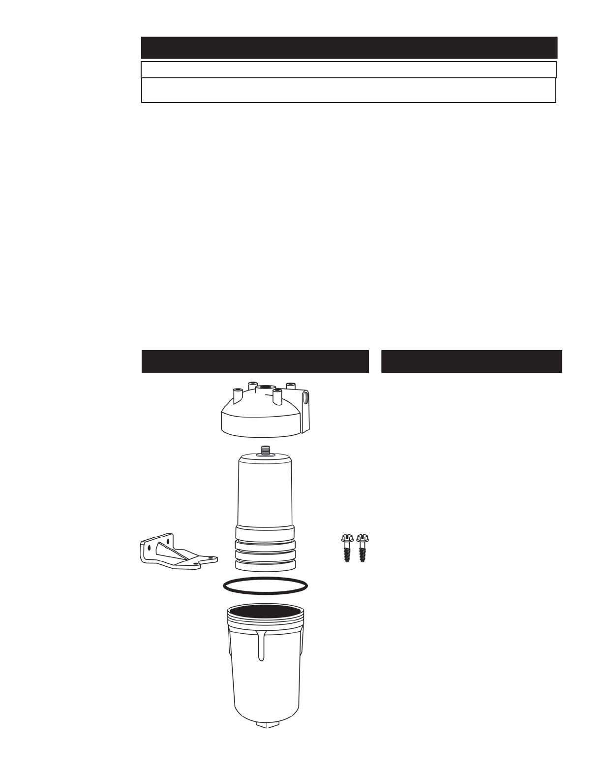
REPLACEMENT PARTS
5 Year Limited Warranty
3M Purification Inc. will not be liable for any loss or dam-
age arising from the use of the Product(s), whether direct,
indirect, special, incidental, or consequential, regardless
of the legal theory asserted, including warranty, contract,
negligence or strict liability. Some states do not allow the
exclusion or limitation of incidental or consequential dam-
ages, so the above limitation may not apply to you.
Limited Warranty: 3M Purification Inc. warrants
this Product will be free from defects in material and
manufacture for five (5) year(s) from the date of ship-
ment. The filter cartridge or filter membrane is warranted
to be free from defects in material and manufacture
for one (1) year. This warranty does not cover failures
resulting from abuse, misuse, alteration or damage not
caused by 3M Purification Inc. or failure to follow instal-
lation and use instructions. No warranty is given as to
the service life of any filter cartridge or membrane as it
will vary depending on application. 3M PURIFICATION
INC. MAKES NO OTHER WARRANTIES OR CONDITIONS,
EXPRESS OR IMPLIED, INCLUDING, BUT NOT LIMITED
TO, ANY IMPLIED WARRANTY OR CONDITION OF
MERCHANTABILITY OR FITNESS FOR A PARTICULAR
PURPOSE OR ANY IMPLIED WARRANTY OR CONDITION
ARISING OUT OF A COURSE OF DEALING, CUSTOMER
OR USAGE OF TRADE. If the Product fails to satisfy
this Limited Warranty during the warranty period, 3M
Purification Inc. will replace the Product or refund
your Product purchase price. This warranty does not
cover labor. The remedy stated in this paragraph is
Customer’s sole remedy and 3M Purification Inc.’s
exclusive obligation.
LIMITED WARRANTY
Head
68586-31
Filter Cartridge
AP217
Bracket
68614-31
O-Ring
36851-35
Housing
64623-31
Screws
68729-31
CAUTION
To reduce the risk associated with property damage due to water leakage:
The disposable fi lter cartridge must be replaced every six months or at the specifi ed service cycle.
3M is a trademark of 3M Company.
Aqua-Pure is a trademark of 3M Company used under license.
© 2010 3M Company. All rights reserved.
3M Purifi cation Inc.
400 Research Parkway
Meriden, CT 06450 USA
Toll Free: 1-800-222-7880
Worldwide: 203-237-5541
Fax: 203-238-8701
www.aquapure.com • www.3Mpurifi cation.com
  • Page 1 1
  • Page 2 2
  • Page 3 3
  • Page 4 4
  • Page 5 5
  • Page 6 6
  • Page 7 7
  • Page 8 8
  • Page 9 9
  • Page 10 10
  • Page 11 11
  • Page 12 12
  • Page 13 13
  • Page 14 14
  • Page 15 15
  • Page 16 16

3M 5528901 Operating instructions

Category
Sanitary ware
Type
Operating instructions

Ask a question and I''ll find the answer in the document

Finding information in a document is now easier with AI

in other languages