Page is loading ...

Installation and Operating Instructions For
AP Easy Full Flow Drinking Water Systems
INSTR2111 0609
Installer: Please leave manual with homeowner.

SAFETY INFORMATION
EXPLANATION OF SIGNAL WORD CONSEQUENCES
WARNING
CAUTION
IMPORTANT NOTES
Read, understand, and follow all safety information contained in these instructions
prior to installation and use of the AP Easy Full Flow Drinking Water Systems. Re-
tain these instructions for future reference.
Intended use:
The AP Easy Full Flow Drinking Water Systems are intended for use in ltering potable water in
homes and has not been evaluated for other uses. The system is typically installed under a
sink, and must be installed by qualied professional installers according to these installation
instructions.
CAUTION
WARNING
Indicates a potentially hazardous situation, which, if not avoided,
could result in death or serious injury and/or property damage.
Indicates a potentially hazardous situation, which, if not avoided,
may result in property damage.
To reduce the risk associated with ingestion of contaminants:
• Do not use with water that is microbiologically unsafe or of unknown quality without adequate
disinfection before or after the system. Systems certied for cyst reduction may be used on
disinfected water that may contain lterable cysts. EPA Establishment #070595-CT-001.
To reduce the risk associated with a hazardous voltage:
• Do not install near electric wiring or piping which may be in the path of a drilling tool when
selecting the position to mount the lter bracket.
To reduce the risk associated with property damage due to water leakage:
• Read and follow Use Instructions before installation and use of this system;
• Installation must comply with existing state or local plumbing codes;
• Install on cold water lines only;
• Protect lter from freezing. Drain lter when room temperature drops below 40°F (4.4°C);
• Do not install if water pressure exceeds 125 psi (862 kPa). If your water pressure exceeds
125 psi, you must install a pressure limiting valve. Contact a plumbing professional if you
are uncertain how to check your water pressure;
• Do not install where water hammer conditions may occur. If water hammer conditions
exist you must install a water hammer arrester. Contact a plumbing professional if you are
uncertain how to check for this condition;
• Do not install on hot water supply lines. The maximum operating water temperature of
this lter system is 100°F (38°C);
• The disposable lter cartridge must be replaced every six months or at the specied
service cycle;
• Do not install near water pipes which will be in path of a drilling tool when selecting the
position to mount the bracket;
• Mount lter in such a position as to prevent it from being struck by other items used in the
area of installation (waste baskets, etc.);
• Ensure all tubing and ttings are secure and free of leaks;
• Do not install in direct sunlight.
• SHUT OFF FUEL SUPPLY TO WATER HEATER after water is shut off.
• Failure to follow instructions may void warranty.
• Allow a minimum of 2” (5 cm) clear space under lter to facilitate cartridge change.
• Install with the inlet and outlet ports as labeled. Make sure not to reverse connections.

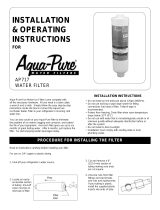
Parts and Materials Included:
1. Filter Cartridge
2. Filter Head Assembly
3. 3/8” Tubing
4. 3/8” x 1/2” Faucet Adapter
5. 3/8” Compression Hex Nut
6 3/8” Ferrule
7. 3/8” Tube Insert
8. #2 Phillips Mounting Screws
Tools Required (not included):
• Drill(Cordlessrecommended)
• Adjustablewrench
• Phillipsheadscrewdriver
• Razorknifeortubecutter
Hot
Cold
3/8" Tubing
Filter
Head
Assembly
#2 Phillips
Mounting
Screws
Filter
Cartridge
3/8"x1/2"
Fa ucet Adapter
3/8" T
3/8" Compression
Hex Nut
3/8" Ferrule
ube Insert
GETTING STARTED
Change this filter at least every six months.Localwaterconditionsandactualvolumeofwatercanaffectfilterlife.
Replaceifanoticeabledropinpressureoccursatthefaucet.
FILTER REPLACEMENT

For Use With Cold Water Only.
NOTE:Removeitemsfromunderthesink.Placecatchbasintheretocollectsmallamountsofwaterthatmayrunout
when disconnecting water supply lines.
1. Turnoffcoldwatersupplyvalveandremoveexistingwater
supplytubingand/orfitting.
2. Selectandmarkalocationunderthesinkthatallowsaccess
forfilterchange.
3. Usingfilterhead/bracketasaguide,fastenFilterHead
Assembly to wall with #2 Phillips mounting screws supplied.
Markholelocationssothatthereis11/2”betweenthe
screws(seeFigure1),fromcenterofeachscrew.When
installed,filterbottomshouldbeatleast21/2”fromsink
cabinetfloortofacilitatecartridgechange.Installscrews,but
onlyhalfway,soyoucaneasilyslipthebrackettowallbefore
firmlysettingscrews.
4. Determinelengthoftubingrequiredfromfilterhead/bracket
tofaucetandfromwatersupplylinetofilterhead/bracketby
holdingtubinginplaceensuringitisofappropriatelength.
Donotkinktubingasthiswillimpedewaterflow.Ifneces-
sary,looptubingaroundtoavoiditbeingkinked.
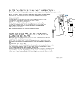
Cuttubingstraightwithautilityknife.(SeeFigure2).
5. Installfaucetadapterfittingtofaucet.Thisshouldbeasnug
fit.Do not overtighten.(SeeFigure3)
Correct Incorrect
Figure 2
To Release Tubing
Push in grey collet to release tubing. With collet
held, pull tubing straight out.
Collet
Backstop
“Using Push-In Fittings”
To Attach Tubing
Push tubing in as far as it will go. Tubing must be inserted
past o-ring and hit backstop. Pull tube to ensure it is secured.
I
nstall F
a
ucet
Ad
apter
Fi
tt
i
n
g
Figure 3
INSTALLATION INSTRUCTIONS
Figure 1
CAUTION
To reduce the risk associated with property damage due to water leakage:
• Ensurealltubingandttingsaresecureandfreeofleaks.

6. Referringtothe“UsingPush-InFittings”section,inserttheblue
tubingintothefaucetadapterfitting,making sure the end of tub-
ing is firmly seated.
Holdthefilterheadassemblyawayfromthewall,pressother
endoftubingintooutletsideasindicatedbyarrowonfilterhead
assembly.(seeFigure4A)
7. Taketheremainingtubing,slipthecompressionhexnutand3/8”
ferruleontothetubing(positionthetaperedendoftheferrule
awayfromthehexnut)andputinthetubeinsert(SeeFigure5).
Fasten this assembly tightly onto 3/8” cold water supply outlet
(SeeFigure6).Pullontubetomakesureagoodconnectionhas
beenmade.Connectotherendtotheinletsideofthefilterhead
assemblyasindicatedbyarrow(seeFigure4B).
8. Placefilterheadassemblyholesovermountingscrewsandpress
downtolockintoplace.Tightenthescrewsforasecurefit.
9. Insertfilterinfilterheadassembly.Turnfilteronequarterturnto
therightuntilitstops.Whenfullyengaged,thetopsurfaceofthe
filterwillbeflushwiththebottomofthefilterheadassembly.The
colorlabelwillfaceforward.
10. Turnonwaterandopenfaucettoflushairfromthesystem.
Flush 10 gallons through system before use (approximately
5 to 7.5 minutes).
Closesinkfaucet.Thesystemisnowreadyforuse.
Note:Whitetubefromheadispressurereliefoutlet.
Inlet
Outlet to
Equipment
B
A
Figure 4
INSTALLATION INSTRUCTIONS (CONTINUED)
FILTER CARTRIDGE REPLACEMENT INSTRUCTIONS
1. Placepanunderfiltertocollectanyresidualwaterduringcartridgechange-out.
2. Graspcartridgeandturntotheleft(counterclockwise)untilcartridgecomestoacompletestop(waterautomatically
turnsoff).Gentlypullcartridgedownwardtoremove.
3. RemoveREDsanitaryprotectivecapfromnewcartridge.
4. Ensurethato-ringsarepresentonthecartridgeandareseatedintogrooves;moisteno-ringswithwater.DONOT
use any petroleum products to lubricate the o-rings.
5. Aligntabsofnewfiltercartridgewithexistingfilterheadandinsertnewfiltercartridgeintohead.Turncartridgetothe
right(clockwise)untilcartridgestops.
6. Flush 10 gallons through system before use (approximately 5 to 7.5 minutes).
TROUBLESHOOTING GUIDE
Figure 5
Figure 6
Water Leaks at Push-In Connections:
Pushtubinginasfarasitwillgo.Ifleakingcontinues,shutoffwaterattheoriginalvalveandremovewaterlinebypush-
inginontheconnectorcollarwhilepullingthetubingaway.Inspecttubingforcracksandscratches.Iftubingiscracked
orscratched,simplycutthatportionawayandreinserttubingintopush-intting.
Makesuretubingiscutstraight.Ifnot,recut.
Ifwaterleaks,pleaseverifythattheo-ringisproperlyseatedinitsgroove.
Water Does Not Flow From The Drinking Water System Faucet:
Checktoseeifthemainwaterlinevalveisopen,allowingwatertoowtothelter.
Water Appears Cloudy or Air Comes Out of the Drinking Water System Faucet:
Flush10gallonsthroughsystembeforeuse(approximately5to7.5minutes)toremoveanycarbonnesortrappedair
inthelterandwaterlines.

3Misatrademarkof3MCompany.
CUNOandAqua-Purearetrademarksof3MCompanyusedunderlicense.
©20093MCompany.Allrightsreserved.
®
ynapmoc
M3
a
CUNO Incorporated
400ResearchParkway
Meriden,CT06450USA
Toll Free: 1-800-222-7880
Worldwide:203-237-5541
Fax: 203-238-8701
www.aquapure.com•www.cuno.com
/