Page is loading ...

IOM
Introduction
The 70 Micro Junction integrates 70 series GO Switch with junction box allowing termina-
tion to the switch directly. Additionally, this product provides the full range of GO Switch
performances in the junction box and the reliability of the GO Switch for use in increased
safety applications. The junction box is available with an M20 or 1/2 NPT conduit entry
and has terminal blocks for ease of end user push-in installation.
The integrated GO switches in the micro junction use permanent magnets which, when
actuated by the presence of a ferrous or magnetic target, change the state of electrical
contacts.
GO Switch 70 Micro Junction
TM
Visit www.topworx.com for
comprehensive information
on our company, capabilities,
and products – including model
numbers, data sheets,
specifications, dimensions,
and certifications.
© 2015 TopWorx, All rights reserved. TopWorx™, and GO Switch™ are all trademarks of TopWorx™. The
Emerson logo is a trademark and a service mark of Emerson Electric. Co. © 2015 Emerson Electric Company. All
other marks are the property of their respective owners. Information herein – including product specifications – is
subject to change without notice.
Asia-Pacific
1 Pandan Crescent
Singapore 128461
+65 6891 7550
Europe
Horsfield Way
Bredbury Industrial Estate
Stockport SK6 2SU
United Kingdom
+44 0 161 406 5155
Africa
24 Angus Crescent
Longmeadow Business Estate East
Modderfontein
Gauteng
South Africa
+27 11 451 3700
Middle East
P.O. Box 17033
Jebel Ali Free Zone
Dubai 17033
United Arab Emirates
+971 4 811 8283
ES-03895-1 R1
GLOBAL SUPPORT OFFICES
Americas
3300 Fern Valley Road
Louisville, Kentucky 40213 USA
+1 502 969 8000
Specifications
Target Material:
Ferrous metal; optional target magnets
Sensing Distance:
Ferrous target: 0.100” (2,54mm)
Increased sensing distance possible with
TopWorx supplied target magnets
Differential:
Ferrous target: 0.020” (0,51mm)
Contact resistance:
<0.5 ohm
Response time:
15 milliseconds
Enclosure Material:
Body tube and lid: 303 or 316 SST
Mounting and Operation Best Practices
Torque specs:
Mounting nuts: 3 lbf·ft [4.1 N·m]
Lid: 14 lbf·ft [19 N·m]
Recommended mounting bracket material: 300 series stainless steel
For the maximum rated sensing distance, ensure a 0.500” gap between threaded
portion of switch and ferrous objects.
Minimum recommended ferrous target dimensions:
0.63” diameter, 0.25” thick
Approximate weight, steel target: 0.32 oz (9g)
In order to achieve maximum contact pressure, ensure that the ferrous target distance
from the switch is 5 times the rated sensing distance in the normally closed states and
1/2 the rated sensing distance in the normally open state.
To minimize undue stress cased by conduit or cables, ensure that the switch is
mounted such that the mounting bracket is near the center of the switch.
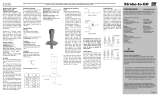
N/C
N/O
COM
Thread Options:
5/8-18 UNF; M18 x 1
Temperature Rating:
Hazadarous Location: -40°C to +75°C
Ordinary Location: -40°C to +105°C
Contact Material:
Palladium silver
Contacts:
Single Pole, Double Throw, Form C
Electrical Ratings: Resistive
4A @ 120VAC / 3A @ 24VDC
Connection Head Conduit Outlet:
1/2" -14NPT or M20.
Axial Sensing
Lateral Sensing
Wiring Diagram
Technical Assistance
TopWorx engineers are available to provide technical assistance on GO
™
Switch
products. However, it is the customer's responsibility to determine the safety and
suitability of the product in their application. It is also the customer's responsibility to
install the switch using the current electrical codes in their region.
Lateral Sensing
Axial Sensing
Normally
closed state
Normally
open state
Installation
For heavy or inductive loads, arc suppression devices or interposing relays are
recommended for contact longevity.
When using long runs of conduit or cable, place supports close to the switch assem-
bly to avoid pulling the assembly out of position.
If switch assembly is mounted on a moving part, ensure that flexible conduit is long
enough to allow for movement, and positioned to eliminate binding or pulling.
Avoid contact between target and switch.
For ease of installation in Cl1 Div 1 environments, Topworx recommends either an
Appleton UNY50 or UNY50NR conduit union.
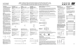
To prevent water ingression through the conduit entry, ensure that a drip loop and
drain plug are installed within 6 inches of the switch.
Basic Dimensions
Example arc
snubber circuit
D
R C
+V
-V
GO Switch
For Topworx terms and conditions of sale, visit Topworx.com
Special Conditions for Safe Use
General
For installation in hazardous locations, check local electrical codes.
The maximum voltage and current shown in the rating label must not be
exceeded.
The switch / terminal assembly is bonded together by the internal cement/
potting. Any attempt to separate the parts (except the threaded cover) will
void the warranty and certification.
A minimum of 5 threads engagement of the lid to the body tube must be
maintained when in service.
NEC
When installed in Cl I Div 1 or Div 2 environment, lead seal fittings are
required within 18" of switch assembly.
ATEX/IECEx
The 70 Series GO Switch assembly shall be suitably earthed by its installa-
tion via the male thread of the GO Switch body.
Do not allow dust layers to build up on the surface of the switch.
No more than one single multi-stranded lead shall be connected to the
terminal unless multiple conductors have been joined in a suitable manner,
e.g. two conductors into a single insulated bootlace ferrule, or any method
indicated on the terminal certificate.
Suitably certified cable entry devices shall be installed in accordance with
IEC60079-14 and must maintain the ingress protection (IP) rating of the
enclosure. The cable entry device thread shall not protrude within the
enclosure body (i.e. shall maintain the clearance to the terminals).
Any unit marked Ex d must be fitted with an Ex d certified gland only.
Any unit marked Ex de may be fitted with either an Ex d or Ex e certified
gland as per the installation requirements.
Inadequate ingression protection
Good ingression protection
Baseefa 14ATEX0236X
IECEx BAS 13.0086X
Ex d IIC T6/T5/T4 Gb
Ex tb IIIC T85°C/T100°C/T135°C Db IP66/68
Tamb: -40°C to + 75°C
0518
II 2 GD
Baseefa 14ATEX0236X
IECEx BAS 13.0086X
Ex de IIC T6/T5/T4 Gb
Ex tb IIIC T85°C/T100°C/T135°C Db IP66/68
Tamb: -40°C to + 75°C
0518
II 2 GD
/