Page is loading ...

IMPORTANT
DreamLine
®
reserves the right to alter, modify or redesign products at any time without prior notice.
For the latest up-to-date technical drawings, manuals, warranty information or additional details please refer
to your model’s web page on DreamLine.com
ENIGMA-Z
S
HOWER
D
OOR &
T
UB
D
OOR
I
NSTALLATION
I
NSTRUCTIONS
##=finish
07- Brushed Stainless Steel
08- Polished Stainless Steel
Model #s
SHDR-62487610-##
SHDR-62607610-##
Model #s
SHDR-62606210-##
Right hand door installation shown
For more information about DreamLine
®
Shower Doors & Tub Doors please visit DreamLine.com
ENIGMA-Z manual Ver 1 Rev 6 09/2017
©2017 DreamLine. All Rights Reserved

Table of Contents
Detailed Diagram of Shower Door Components
Parts List
Section title
Page
Tools
Preparation
Installation
Stoppers
SafeStop™ Bumper
Vinyl Seals
Product maintenance
Wheel and Roller Guard Adjustments
24
19
21, 22
20
18
10-23
9
8
7
6
4
5
2, 3
Model Information
Reinforcement Locations
Installation Information
ENIGMA-Z manual Ver 1 Rev 6 09/2017
©2017 DreamLine. All Rights Reserved

2ENIGMA-Z manual Ver 1 Rev 6 09/2017
©2017 DreamLine. All Rights Reserved
ENIGMA-Z Enclosure
MODEL #s
SHEN-6234480-##
SHEN-6234600-##
NOTE: This manual will describe the installation of the single threshold model
of the Enigma-Z.
For the ENIGMA-Z Enclosure installation, please use the manual that is
packaged with the return panel glass.
When installing one of the enclosure models, the return
panel glass must be installed first.
Use the manual that is packed with the return panel glass
in place of this manual.
IMPORTANT
DreamLine
®
reserves the right to alter, modify or redesign products at any time without prior notice.
For the latest up-to-date technical drawings, manuals, warranty information or additional details please
refer to your model’s web page on DreamLine.com
ENIGMA-Z Enclosure
MODEL #s
SHEN-623448-##
SHEN-623460-##
##=finish
07- Brushed Stainless Steel
08- Polished Stainless Steel
Right-hand return panel installation shown
For more information about DreamLine
®
Shower Doors & Tub Doors please visit DreamLine.com
SHOWER ENCLOSURE IINSTALLATION INSTRUCTIONS
©2017 DreamLine. All Rights Reserved
ENIGMA Z Enclosure Manual Ver 1 Rev 4 10/2016

This model is treated with DreamLine’s
exclusive ClearMax
TM
Glass technology.
This is a specially formulated coating
that prevents the build up of soap and
water spots.
Install the surface with the ClearMax
TM
label towards the inside of the shower.
Please note that depending on the
model, the glass may be coated on
either one or both surfaces.
For best results, squeegee the glass after
each use and dry with a soft cloth.
3ENIGMA-Z manual Ver 1 Rev 6 09/2017
©2017 DreamLine. All Rights Reserved

Install studs OR install 2”x 6” wood blocking between the studs where the
Guide Rail Brackets will attach to the wall
Reinforcement for Enigma Series
Heavy Glass frameless sliding shower or tub door
2” X 6”
Stud
or
threshold
or tub deck
measured
from threshold
or tub deck*
(see list below)
2” X 6”
*Blocking height requirement (to center)
as measured from threshold or tub deck:
Enigma Air = 73” for shower ht / 59” for tub ht
Enigma X = 72-1/2“ for shower ht / 58-1/2” for tub ht
Enigma Z = 73-1/2” for shower ht / 59-1/2“ for tub ht
Enigma = 75-1/2” for shower ht only
threshold
or tub deck
4ENIGMA-Z manual Ver 1 Rev 6 09/2017
©2017 DreamLine. All Rights Reserved

5ENIGMA-Z manual Ver 1 Rev 6 09/2017
©2017 DreamLine. All Rights Reserved
Right hand door installation shown as an example
!
A
B
D
F
E
C
B
A
IMPORTANT INFORMATION
REGARDING THE INSTALLATION
OF THIS SHOWER DOOR
A
Guide Rail Brackets must be firmly
attached to the wall. Installation into a
stud is strongly recommended.
All of the guide rail bracket set
screws must be tightened.
B
Thread Lock must be applied to both
stopper set screws.
Panel-side stopper must be installed
into the pre-drilled stopper hole in
the upper guide rail.
Door-side stopper must be installed
at the proper position to stop the
door from contacting the wall.
E
Bumper Vinyl Seal must be installed on
the closing edge of the door glass.
D
Roller Guards must be postioned and
secured within 1/16” of Upper Guide Rail.
F
The Guide Block must be screwed to the
threshold and installed square to the panel
glass and door glass. Installing the guide
block crooked may damage the bottom edge
of the door glass and lead to breakage.
C
Roller Wheel Assembly Set Screws
must be tightened.
PLEASE READ THE ENCLOSED INSTALLATION
MANUAL FOR DETAILS REGARDING PROPER
INSTALLATION.
THE LATEST VERSION OF THE INSTALLATION
MANUAL IS AVAILABLE TO VIEW OR PRINT
AT DREAMLINE.COM

Preparation
1. Prior to installation, examine all boxes and packages for shipping damage and compare the piece
count with your packing slip. After opening all boxes and packages read this introduction carefully.
Check that all of the needed parts are included in the package by checking off the components on the
“Detailed Diagram of Shower Door Components”. If the unit has been damaged, has a finishing defect,
or has missing parts, please contact our customer support department within 3 business days of the
delivery date. Please note that DreamLine
®
will not replace any damaged products or missing
parts free of charge after 3 business days or if the product has been installed. Feel free to contact
DreamLine
®
if you have any questions, and please provide an order number, job name or other proof
of purchase to help identify the original order.
2. Please note that you should consult your local building codes with questions on installation
compliance standards. Building and plumbing codes may vary by location, and DreamLine
®
is not
responsible for code compliance standards for your project and will not accept any returns.
3. If this unit is going to be installed in new construction, please install all of the required plumbing and
drainage before installing the shower. Use a competent and licensed (if required by local code)
plumber for all plumbing installation.
4. Make sure that prior to beginning the installation, the surfaces are leveled and solid and will be able
to support the total weight of the unit. Also make sure the walls are at right angles. Irregular installa-
tion surface level, radius corners or improper angle of side walls will result in serious problems for your
installation. Please, note that some adjustments and drilling might be necessary during the installation
process.
5. Protect all primary surfaces of the product during installation. Never set your glass down directly
onto a tile floor. Leave corner protectors in place until necessary to remove them. Always use a piece of
wood or cardboard to protect the bottom edge and corners of the glass prior to and during installa-
tion.
6. This unit must be installed upon a finished threshold and against finished walls.
7. This model has NO adjustment for out-of-plumb wall conditions. Verify that your walls are
plumb before proceeding with the installation.
8. This model requires that you drill into the threshold for proper installation.
9. Take extra care during installation when you set your glass directly onto the threshold as instructed.
10. This door requires a minimum 2-3/8”of flat threshold space for installation.
Please note that Step #9 calls for installation of the Guide Rail Brackets to the wall using
anchors. However, the manufacturer strongly recommends installing these heavy doors to the
studs or to pre-installed 2“x 6” wood reinforcements behind the wall.
Attention: This door is extremely heavy and requires professional installation and 2 installers.
NOTE: The Enigma Series doors and enclosures are reversible for left or right-hand installation. This manual will
show the right-hand door installation. For a left-hand door installation, simply begin on the opposite wall and
reverse the orientation of the parts as necessary. The Shower height model is shown. The Enigma-Z tub height
installation follows the same steps.
6ENIGMA-Z manual Ver 1 Rev 6 09/2017
©2017 DreamLine. All Rights Reserved
!

Tools
Tip: Measure the finished opening before
proceeding with the installation to be sure
that the correct model size has been ordered.
Soft Head
Hammer
Silicone
Tape
Measure
Pencil
Screwdriver
Phillips
(Ø3/8")
(10 mm)
Drill bit
(Ø5/16")
(8 mm)
Drill bit
Level
Drill
Power
Chop saw and Hacksaw
(Ø1/8")
(3 mm)
Drill bit
Painter’s Tape
Carpenter’s
Square
NOTE: Unpack your unit carefully and inspect it. Lay it out and identify all parts using the detailed
diagram and packing list in this manual as a reference. Before discarding the carton, check for small
hardware bags that may have fallen to the bottom of the box. If any parts are damaged or missing,
please contact DreamLine
®
for replacement. The shipping boxes may contain extra parts not used in
your model configuration.
NOTE: Retain these installation instructions for future reference.
Tip: Before installation, cover the shower drain to
prevent losing small parts.
Tip: Set screw gun clutch to low setting when
installing screws and bolts to
prevent stripping the heads.
7ENIGMA-Z manual Ver 1 Rev 6 09/2017
©2017 DreamLine. All Rights Reserved
W
Top
Middle
Bottom
Professional-grade
Glass suction cup
Extender driver bit

Detailed Diagram of Shower Door Components
8ENIGMA-Z manual Ver 1 Rev 6 09/2017
©2017 DreamLine. All Rights Reserved
The glass surface
with the ClearMax™
label must be
installed to face
inside of the shower
17
16
19
20
18
10
11
12
13
14
15
5
6
7
9
1
2
3
4
8
21

Parts List
9ENIGMA-Z manual Ver 1 Rev 6 09/2017
©2017 DreamLine. All Rights Reserved
01
ITEM #
02
03
04
05
06
07
08
09a
11
DESCRIPTION
PART NUMBER
QTY
Door stopper
2pcs
2pcs
12
13
14
15
16
17
18
19
20
Stationary Glass
Upper guide rail
Roller assemblies
Door Glass
Handle
Glass bracket
Guide rail bracket
Wall anchor Ø3/8"
Large Truss head screw ST6x65
2pcs
Hex wrench 3mm,4mm,5mm
Guide block(with caps)
1pc
1pc
1pc
1pc
Bumper seal strip
Anti-water strip
Anti-splash threshold
Threshold cap
Countersunk screw ST4.2x25
Truss head screw ST4.2x5
5
Wall bracket
Wall anchor Ø5/16"
09b
10
2pcs
2pcs
2pcs
1pc
2pcs
1pc
1pc
2pcs
1pc
1pc
3pcs
1pc
1pc
1pc
063007100-1470
4876" 010019001
063001100-1470
48" 07121043 / 07125043
04100011-0660
07311018
07021036
07221003
07021097
07021098
07021004
07021037
07550044
07550045
090112
098003,098004,098005
091104
090113
07551068
Thread lock adhesive
21
1pc
07021154
Bumper
/04100041-0660
04100011-0813
/04100041-0813
/ 07554068
/ 07025154
063007100-1825
0
63001100-1825
62"
76"
62"
76"
48"
60"
6062" 010019002
6076" 010019003
4876" 010019004
6062" 010019005
6076" 010019006
60" 07121044 / 07125044
/ 07025036
/ 07315018
/ 07225003
/ 07025097
/ 07025037
/ 07025098
/ 07024004
160012
BOLD digit indicates finish color: 1= Polished, 4 or 5= Brushed

Installation steps
10ENIGMA-Z manual Ver 1 Rev 6 09/2017
©2017 DreamLine. All Rights Reserved
Fig. 1
Fig. 2
door end
door end
glass bracket
holes
W
Top
Middle
Bottom
threshold
2-3/8”
minimum
Note: The minimum threshold requirement for
the ENIGMA-Z is 2-3/8” of flat threshold space.
1. Measure the distance between the two finished walls at
the top, middle and bottom. This distance is marked as “W”.
Also check the threshold for level and the walls for plumb.
Use the “W” dimension at the model height to cut the
Upper Guide Rail (#03) to size for your opening. (Fig. 1)
2. The Upper Guide Rail (#03) has been precut for your
model width of: 48” or 60” (Please Note: the actual rail is
shorter than the model width by design).
Cut the Upper Guide Rail (#03) from the door end only,
which is the end that is farther from the Glass Bracket (#07)
holes. (Fig. 2)
The length to cut off will be L:
Model Width – Finished Opening W = cut off length L
FOR EXAMPLE:
If the model width is 48” and your finished opening is 46”,
then you will need to cut 2” off of the rail from the door end.
Example: 48”– 46”(W) = 2” cut off (L)
*Note that this is only an example and the actual cut-off
length will vary based on the actual finished opening
dimension.

11ENIGMA-Z manual Ver 1 Rev 6 09/2017
©2017 DreamLine. All Rights Reserved
TIP: Mark the location of the high spot on the
outer surface of the adjustment disk with a felt
tip pen to make adjustment easier to see.
(EQ=Equal distance)
Fig. 4
Fig. 3
Door end of guide rail
High spot of disk bushing
EQ
EQ
measure
glass bracket
adjustment
disk
after adjusting the disk, use this hole to hold
it in place with a small allen wrench while
tightening main bolt
1
2
4
3
6
5
outside
stopper hole
stationary
panel-end
door-end
thread
lock
outside
panel side
*NOTE: The outer glass bracket disk has an eccentric bushing for adjustment. Be sure to install both
glass bracket disks with the high spot of the bushing pointed towards the door end of the guide rail.
See the detail of the disks below as viewed from inside prior to installing on the glass.
3b. Slide the Door Stoppers (#01) onto each end of the Upper Guide Rail (#03) and secure them
using the 4mm Hex Wrench (#11). Install the panel-end stopper into the pre-drilled stopper hole in
the Upper Guide Rail and apply Thread Lock (#20) to the set screw (Fig 4.3). Install the door-end
stopper approximately 4” from the end of the guide rail. (The door-end stopper position will be adjusted
in a later step after the door glass is installed).
3a. Attach the Upper Guide Rail (#03) to the Stationary Glass (#02) with the Glass Brackets (#07) and
tighten the bolts into the pre-drilled holes in the Upper Guide Rail (#03). Make sure both adjustment
disks are installed in the same direction with the high spot towards the door end (see *NOTE below).
Make sure the guide rail is parallel with the top edge of the stationary panel glass. (Fig. 3)
3c. Slide the Guide Rail Brackets (#08) onto each end of the Upper Guide Rail (#03) and secure
them. Next, assemble the Wall Bracket (#19) onto the bottom corner of the Stationary Glass (#02)
with the bolt facing into the shower as shown in Fig. 4.5. Use the supplied gaskets to protect the glass.
(Fig. 3 and Fig. 4)

12ENIGMA-Z manual Ver 1 Rev 6 09/2017
©2017 DreamLine. All Rights Reserved
Fig. 6
Fig. 5
TIP: Use the guide block for
reference when positioning
your stationary glass on the
threshold.
Lower guide rail Raise guide rail
Glass Bracket adjustments
4. The Guide Block (#12) should be centered on the threshold, not the stationary panel glass.
In preparation for dry fitting the Stationary Glass Panel (#02), Upper Guide Rail (#03), Anti-Splash
Guard (#15) and Guide Block (#12), use the Guide Block (#12) as a reference to mark the wall and base
on the stationary panel side where the stationary panel glass will be installed. (Fig. 5)
5. Place the Stationary Glass (#02) onto the
threshold or tub deck aligned with the marks made in
Step #4 and butt it up against the wall.
Note: The Stationary Glass (#02) installs to the
outside of the Upper Guide Rail (#03).
Make sure the Stationary Glass (#02) is plumb and the
Guide Rail (#03) is level. Adjust the Guide Rail (#03)
to level by using the Glass Brackets (#07). If necessary,
rotate the elliptical adjustment disk on the outside of
the Glass Bracket (#07), and then re-tighten the bolt
while holding the adjustment disk in place.
Dry fit the Guide Block (#12) into the notch of the
Stationary Glass (#02). (Fig. 6)

13ENIGMA-Z manual Ver 1 Rev 6 09/2017
©2017 DreamLine. All Rights Reserved
1
2
3
Fig. 7
1 2 3
X-3/8"
Fig 8
“X”
“X”
6. Once the Upper Guide Rail (#03) is leveled, mark the position of the Wall Bracket (#19) and Guide
Rail Brackets (#08) on the wall. (Fig. 7)
7. Mark the Guide Block (#12) position and the holes for drilling on the threshold. (Make sure the
Guide Block (#12) is square to the Stationary Glass (#02)). Measure the distance from the door-side
wall to the far edge of the Guide Block (#12). This distance will be “X”. The Anti-Splash Guard (#15)
will need to be cut to the size of: X (-) 3/8”. Insert the Anti-Splash Guard (#15) into the Guide
Block (#12) and align the Anti-Splash Guard (#15) parallel to the front edge of the threshold or tub
deck and mark its position on the theshold. (Fig. 8)

14ENIGMA-Z manual Ver 1 Rev 6 09/2017
©2017 DreamLine. All Rights Reserved
Separate the Guide Rail Bracket (#08) sleeve from
the base by loosening the set screws (leave both of
the Guide Rail Bracket sleeves on the upper guide
rail)
1
1
2
3**
4**
5** 6**
2
3
Fig. 9
base
sleeve
Guide Rail Bracket (#08)
Ø3/8”
(10mm)
Fig 10
Wall Bracket (#19)
!
Ø5/16”
(8mm)
Ø3/8”
(10mm)
Ø1/4”
(6mm)
Ø1/4”
(6mm)
**NOTE: The manufacturer strongly recommends
installing the guide rail brackets into studs or pre-installed
2”x 6“ wood reinforcements behind the wall.
For the recommended
installation into a stud,
drill a Ø1/4” hole up to
the stud and let the
screw bore into the wood.
Do not use the wall
anchors.
8. Set the Stationary Glass (#02) and
Upper Guide Rail (#03) aside, along with
the Guide Block (#12) and Anti-Splash
Guard (#15).
Remove the Guide Rail Brackets (#08)
from the Upper Guide Rail (#03) (as
shown below) and the Wall Bracket (#19)
from the Stationary Glass (#02). Place the
Wall Bracket (#19) and Guide Rail
Bracket (#08) on the outlined positions
and mark the holes for drilling. (Fig. 9)
**NOTE: Step #9 has an option for installing the guide
rail brackets to the wall using anchors. However, the
manufacturer strongly recommends installing these heavy
doors to the studs or to pre-installed 2”x 6“ wood
reinforcements behind the wall in the area where the guide
rail brackets will be attached to the wall.
9. Drill the hole for the Wall Bracket (#19) using a Ø5/16”
drill bit and insert the Wall Anchors (#9b) (Fig. 10.1)
**Drill the holes for the Guide Rail Brackets (#08) using a
Ø3/8” drill bit and insert the Wall Anchors (9a). (Fig. 10)

15ENIGMA-Z manual Ver 1 Rev 6 09/2017
©2017 DreamLine. All Rights Reserved
3
1
2
Fig. 11
Fig. 12
Painter’s Tape
protective
padding
protective
padding
1
2 3
!
10. Fasten the Wall Bracket (#19) to the wall using the Truss Head Screw ST4.2×55 (#18).
Mount the base part of the Guide Rail Brackets (#08) onto both walls using the Large Truss Head
Screw ST6×65 (#10).
Note that the adjustment Set Screws on the brackets must be aligned
vertically for easier access to adjust for level after the glass is installed. (
Fig. 11)
11.
Apply silicone to the bottom of the Anti-Splash Guard (#15) and the Guide Block (#12). Insert
one end of the Anti-Splash Guard (#15) fully into the Guide Block (#12) and align both pieces on the
threshold or tub deck using the marks made in Step #7. Apply silicone to the Anti-Splash Guard
Cap (#16), and place it at the wall end of the Anti-Splash Guard (#15) (Fig12.3). Apply several strips
of painter’s tape to hold the Anti-Splash Guard (#15) and Cap (#16) in place while the silicone cures.
(Fig. 12)
NOTE: Before you install the Stationary Glass (#02),
bring the Door Glass (#05) into the shower and lean it
against the wall.
Make sure the door is facing in the right
direction for installation
with the handle holes on the correct
side. After the Stationary Glass (#02) is installed, it may not be
possible to easily get the door glass into the shower or to turn it
around. Always use padding to protect the door glass and
shower surfaces.
NOTE: Do Not attach the handle to the door glass until
instructed. Do Not attempt to lift the door glass with the
handle as this may result in damage to the glass and/or
serious personal injury. Use a professional grade glass
suction cup and an assistant.

16ENIGMA-Z manual Ver 1 Rev 6 09/2017
©2017 DreamLine. All Rights Reserved
2
1
1
2
3
Fig. 14
Fig. 13
Painter’s Tape
Use Caution
outside
The Guide Block (#12) must be
installed squarely onto the threshold
and stationary panel glass
90°
anti-splash guard
overhead view of
guide block and
stationary panel glass
on threshold
!
protective
padding
panel glass
right-hand installation shown as an example
12. Place the Stationary Glass (#02) with the Upper Guide Rail (#03) onto the threshold with the
notch fitting into the
Guide Block (#12).
Position the Stationary Glass (#02) against the wall. (Please
note that the Stationary Glass (#02) installs on the outside and the Upper Guide Rail (#03) goes on
the inside of the shower). (Fig. 13)
13. Re-position the Stationary Glass (#02) and Upper Guide Rail (#03) onto the threshold and
fasten both sleeves of the Guide Rail Brackets (#08) to the brackets on the walls.
Tighten the set screws on the Guide Rail Brackets (#08) to secure the Upper Guide Rail (#03).
Make sure to position the bracket set screws so that they are accessible from the top and bottom.
(Fig 14.1 and 14.2)
Assemble the Wall Bracket (#19) at the bottom corner of the Stationary Glass (#02). Use the clear
vinyl gasket between the glass and the metal parts to avoid contact with the glass, then tighten the
bolt with the supplied allen wrench. (Fig. 14)

17ENIGMA-Z manual Ver 1 Rev 6 09/2017
©2017 DreamLine. All Rights Reserved
TIP: Level the installed Upper Guide Rail (#03) as necessary using the Guide Rail Brackets (#08)
first and then the Glass Brackets (#07) (see Fig. 3 in step #3a). Start adjustments from the door
end. (Fig. 16 and Fig. 17)
2
1*
3
Fig. 16
Fig. 17
Panel end
Door end
Glass bracket
Guide Rail Bracket
(Right hand door installation shown as example)
Fig. 15
NOTE: Use the Guide Rail Bracket (#08)
set screws to adjust the Guide Rail (#03)
to level.
Ø1/8"
To Lower the Rail:
Loosen the top set
screw and tighten the
bottom set screw.
To Raise the Rail:
Loosen the bottom set
screw and tighten the
top set screw.
Lower guide rail Raise guide rail
Glass Bracket adjustments
14. Fasten the Guide Block (#12)
to the threshold or tub deck with the
Countersunk Screw ST4.2×25 (#17).
(Fig. 15)

18ENIGMA-Z manual Ver 1 Rev 6 09/2017
©2017 DreamLine. All Rights Reserved
1
2
3
65
7
4
Roller Installation
Tool
Fig. 19
1
2
3
Door
Door
Panel
Fig. 18
!
Do Not hang or drape a towel or wash cloth over the Enigma guide rail as this may
cause the roller wheels to get stuck and possibly cause serious damage or injury.
15. Use the Roller Installation tool to install the two
Roller Assemblies (#04) onto the Door Glass (#05).
(Fig. 18.1)
Suspend the door by hanging the Roller Assemblies (#04)
onto the Upper Guide Rail (#03) and sliding the bottom
edge of the Door Glass (#05) into the groove of the
Guide Block (#12).
Be careful not to damage the bottom edge of the door
glass during installation.
(Fig. 18 and Fig. 19)
16. Press the Anti-Water Strip (#14) on the vertical edges of the Stationary Glass (#02) and the Door
Glass (#05). Press the Bumper Seal Strip (#13) onto the vertical edge of the Door Glass (#05). Attach
the Handle (#06) to the Door Glass (#05). (Fig. 19)

19ENIGMA-Z manual Ver 1 Rev 6 09/2017
©2017 DreamLine. All Rights Reserved
Fig. 20
*Roller guards must be tight and
the distance beneath the guide rail
should be 1/16”.
roller height
adjustment range
roller guard
1
16”
Fig. 21
!
!
20
Add Thread Lock (#20) to the
roller guard set screws to prevent
them from loosening.
NOTE: The door glass must be supported during this process. Use a 1/4” shim, a glass suction cup
and an assistant. Adjust the tilt of the door glass as necessary by loosening the set screws on either
side of the wheel. Raise or lower the wheel to the proper height and re-tighten the set screws.
Only adjust one wheel at a time.
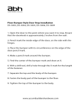
18. Position the Roller Guards on both Roller
Assemblies (#04) to within 1/16” of the
Upper Guide Rail (#03) to ensure that the
Door Glass (#05) is secure. (Fig. 21)
TIP: During door glass adjustment, you must support the door glass so that it does not make
contact with the guide block. Leave approximately 1/8” of space between the bottom of the door
glass and the guide block. Use a 1/4” shim on the threshold to prevent adjusting the door glass
too low.
17. If necessary, the door glass can be adjusted to create a better seal with the wall. The Bumper Seal
Strip (#13) must be installed on the Door Glass before making any adjustments. Use the set screws
to raise or lower the wheels. Fully tighten all set screws after all adjustments are made. (Fig. 20)
/