Page is loading ...

Please review this entire manual prior to installation.
IMPORTANT
DreamLine
®
reserves the right to alter, modify or redesign products at any time without prior notice.
For the latest up-to-date technical drawings, manuals, warranty information or additional details please refer
to your model’s web page on DreamLine.com
For more information about DreamLine
®
Shower Doors, Tub Doors & Enclosures, please visit DreamLine.com
ENIGMA AIR
SHOWER DOOR / TUB DOOR INSTALLATION INSTRUCTIONS
Right-hand door installation shown
MODEL #s
SHDR-64487610-##
SHDR-64547610-##
SHDR-64607610-##
MODEL #
SHDR-64606210-##
##=finish
07- Brushed Stainless steel
08- Polished Stainless Steel
ENIGMA AIR manual Ver 1 Rev 5.2 02/2018
©2018 DreamLine. All Rights Reserved

This model is treated with DreamLine’s
exclusive ClearMax
TM
Glass technology.
This is a specially formulated coating
that prevents the buildup of soap and
water spots.
Install the surface with the ClearMax
TM
label towards the inside of the shower.
Please note that depending on the
model, the glass may be coated on
either one or both surfaces.
For best results, squeegee the glass after
each use and dry with a soft cloth.
ENIGMA AIR manual Ver 1 Rev 5.2 02/2018
©2018 DreamLine. All Rights Reserved

ENIGMA AIR manual Ver 1 Rev 5.2 02/2018
©2018 DreamLine. All Rights Reserved
Installing the Enclosure model
Handing Information
Troubleshooting and Maintenance Tips
Detailed Diagram of Shower Door Components
Parts List
Installation Steps
Table of Contents
Section title
Page #
Preparation
Tools
Reinforcement Information
Vinyl Seals
Stoppers
SafeStop™ Bumper
Product Maintenance
6
5
4
3
2
10-29
9
7
8
30
Maintenance Checklist
31
28
26-27
25

Handing Information
NOTE: This door is reversible for right or left-hand door installation. The right-hand door installation is
shown as an example throughout this manual. For the left-hand door installation, simply begin on the
opposite wall and reverse the orientation of the steps shown.
2ENIGMA AIR manual Ver 1 Rev 5.2 02/2018
©2018 DreamLine. All Rights Reserved
Left-Hand door installation
Right-Hand door installation
D
OOR
P
ANEL
D
OOR
P
ANEL

Installing the Enclosure model
3ENIGMA AIR manual Ver 1 Rev 5.2 02/2018
©2018 DreamLine. All Rights Reserved
ENIGMA AIR ENCLOSURE
MODEL #s
SHEN-6434480-##
SHEN-6434600-##
##=finish
07- Brushed Stainless Steel
08- Polished Stainless Steel
ENIGMA AIR ENCLOSURE
SHOWER ENCLOSURE INSTALLATION INSTRUCTIONS
IMPORTANT
DreamLine
®
reserves the right to alter, modify or redesign products at any time without prior notice.
For the latest up-to-date technical drawings, manuals, warranty information or additional details please refer
to your model’s web page on DreamLine.com
For more information about DreamLine
®
Shower Doors, Tub Doors & Enclosures, please visit DreamLine.com
ENIGMA AIR ENCLOSURE manual Ver 1 Rev 2 06/2018
©2018 DreamLine. All Rights Reserved
Right - Hand return panel installation shown
NOTE: This manual will describe the installation of the single threshold model
of the ENIGMA AIR.
For the ENIGMA AIR Enclosure installation, use the installation manual that
is packaged with the return panel glass.

4ENIGMA AIR manual Ver 1 Rev 5.2 02/2018
©2018 DreamLine. All Rights Reserved
Roller wheels tight with
proper clearance beneath the
door glass and guide block
Roller guards
positioned properly
and tight within 1/16”
beneath guide rail
Guide block screwed down
and square with glass
Stopper properly
positioned and tight
-door stops well before
handle can contact the
panel glass when door
is in the fully open
position
Stopper properly positioned and
tight so that the Door stops against
the stopper and prevents the Door
from making hard contact with the
wall but allows the bulb vinyl to seal
Guide Rail level
To secure the Stoppers (#05):
Apply the Thread Lock adhesive to the
threads of the set screws during the nal
installation. Fully tighten the set screws with
the supplied Allen wrench.
Stopper
Thread Lock Adhesive
Recommend to apply thread lock to:
• Stopper set screws
• Roller guard bolts
• Wheel bolts
• Glass Bracket bolts
ENIGMA-AIR
troubleshooting and
maintenance tips
Roller wheels adjusted as
needed so that the bulb
vinyl seal makes even
contact with the wall
from top to bottom
Guide Rail bracket ush with
wall and set screws tight;
Installation into a
stud strongly recommended
Glass brackets
tight
Panel Glass sits ush
on the threshold
All rubber gaskets and sleeves installed properly between
all hardware and glass to prevent glass to metal contact
Guide Rail
bracket ush
with wall and
set screws
tight
Bulb vinyl seal
installed
The bulb vinyl seal on
the edge of the door
makes even contact
with the wall when the
door is fully closed
Inspect bottom
corners of door glass
for damage.
**Units with
damaged door glass
should not be used
until door glass has
been replaced**
Right Hand door installation shown as an example
Handle tight
Rotate disk to adjust
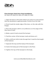
Bumper is
secured in
position with
3M tape or
screwed to
the wall
Door Glass
Panel Glass
* Stopper Locations as measured from the
wall to the center of the stopper:
• Panel side: 4-3/4” (+/-) (but no less than
4-1/2” )
• Door side: 4” (+/-) (depends on opening
conditions)

5
ENIGMA AIR manual Ver 1 Rev 5.2 02/2018
©2018 DreamLine. All Rights Reserved
Install studs OR install 2”x 6” wood blocking between the studs where the
Guide Rail Brackets will attach to the wall
Reinforcement for Enigma Series
Heavy Glass frameless sliding shower door
2” X 6”
Stud
or
threshold
or tub deck
measured
from threshold*
(see list below)
2” X 6”
threshold
or tub deck
*Blocking height requirement (to center)
as measured from threshold or tub deck:
Enigma Air, Enigma Sky = 73” for shower ht / 59” for tub ht
Enigma X, Enigma XO = 72-1/2“ for shower ht / 58-1/2” for tub ht
Enigma Z = 73-1/2” for shower ht / 59-1/2“ for tub ht
Enigma = 75-1/2” for shower ht only

Preparation
!
1. Prior to installation, examine all boxes and packages for shipping damage and compare the piece count
with your packing slip. After opening all boxes and packages read this introduction carefully. Check that
all of the needed parts are included in the package by checking off the components on the “Detailed
Diagram of Shower Door Components”. If the unit has been damaged, has a finishing defect, or has
missing parts, please contact our customer support department within 3 business days of the delivery
date. Please note that DreamLine
®
will not replace any damaged products or missing parts free of
charge after 3 business days or if the product has been installed. Contact DreamLine
®
if you have any
questions and please provide an order number, job name or other proof of purchase to help us identify
your original order.
2. If this unit is going to be installed in a new construction, install all of the required plumbing and
drainage before installing the shower. Use a competent and licensed (if required by local code)
plumber for all plumbing installation.
3. Please note that you should consult your local building codes with questions about
installation compliance standards. Building and plumbing codes may vary by location and
DreamLine
®
is not responsible for code compliance standards for your project and will not accept
any returns.
4. Make sure that prior to beginning the installation, the surfaces are leveled and solid and will be able to
support the total weight of the unit. Also make sure the walls are at right angles. Irregular installation
surface level, radius corners or improper angle of side walls will result in serious problems for your
installation. Please note that some adjustments and drilling may be necessary during the installation
process.
5. Protect all primary surfaces of the product during installation. Never set your glass down directly onto a
tile floor. Leave corner protectors in place until necessary to remove them. Always use a piece of wood or
cardboard to protect the bottom edge and corners of the glass prior to and during installation.
6. This unit must be installed upon a finished threshold and against finished walls.
7. This model does NOT have any adjustment for out-of-plumb conditions. Verify that your walls are
plumb before proceeding with the installation.
8. This model requires that you drill into the threshold for proper installation.
9. Installation of the Guide Rail brackets into a stud or 2” x 6“ wood reinforcement is strongly
recommended.
10. This model requires a minimum 2-1/4” of flat threshold space for installation.
11. Professional Installation Required.
NOTE: This manual will describe the shower door installation. Please follow the same sequence of
installation steps for the tub door installation.
NOTE: DO NOT attach the handle to the door glass until instructed to do so. DO NOT use
the handle to lift the glass during installation. This may result in damage to the glass and/or
serious injury. Always use an assistant and/or a professional grade glass suction cup when
handling heavy glass panels.
6
ENIGMA AIR manual Ver 1 Rev 5.2 02/2018
©2018 DreamLine. All Rights Reserved

Tools
Tip: Measure the finished opening before
proceeding with the installation to be sure
that the correct model size has been
ordered.
Tip: Prior to installation, cover the
shower/tub drain with tape to prevent
losing screws or small parts.
NOTE: Unpack your unit carefully and inspect it. Lay it out and identify all parts using the detailed
diagram and packing list in this manual as a reference. Before discarding the carton, check for small
hardware bags that may have fallen to the bottom of the box. If any parts are damaged or missing,
please contact DreamLine
®
for replacement. The shipping boxes may contain extra parts not used in
your model configuration.
NOTE: Retain these installation instructions for future reference.
Tip: Set screw gun clutch to low setting
when installing screws and bolts to
prevent stripping the heads.
7
ENIGMA AIR manual Ver 1 Rev 5.2 02/2018
©2018 DreamLine. All Rights Reserved
W
Top
Middle
Bottom
Threshold must be level.
Silicone
Tape
Measure
Level
Phillips
Screwdriver
Pencil
Carpenter’s Square
Drill
Power
(D=1/8")
Drill bit
(D=5/16")
Drill bit
Painter’s Tape
Hammer
Soft Head
Metal File
Chop saw and Hacksaw
Professional-grade
Glass suction cup
Extender driver bit
!

Detailed Diagram of Shower Door Components
8
ENIGMA AIR manual Ver 1 Rev 5.2 02/2018
©2018 DreamLine. All Rights Reserved
The glass surface
with the ClearMax™
label must be
installed to face
inside of the shower
26
20
6a
6b
7
4
8
9
5
1
13
15
16
2
3
18
19
17
10
11
12
6
21
14
D
OOR
P
ANEL

Parts List
ENIGMA AIR manual Ver 1 Rev 5.2 02/2018
9
©2018 DreamLine. All Rights Reserved
04
ITEM #
05
06
QTYDESCRIPTION
Stationary glass
Guide Rail Bracket (6a&6b)
Stopper
02
03
Countersunk screw ST4.2X40
01
U-Channel
5/16" plastic wall anchor
ST4.2X55 Truss Head screw
07
11
12
13
09
10
08
14
17
18
19
15
16
21
20
Door glass
Guide Rail
Glass Bracket
Roller
Roller Guard
Threshold End Cap
Anti-splash Threshold
Guide Block
Anti-water side strip
Bumper strip
Handle
Allen wrench (4mm)
Thread Lock Adhesive
Round head screw ST4.2X25
26
Bumper
1 PC
1 PC
1 PC
1 PC
1 PC
7 PCS
1 PC
1 PC
1 PC
1 PC
1 PC
1 PC
1 PC
1 PC
2 PCS
2 PCS
2 PCS
2 PCS
2 PCS
2 PCS
2 PCS
2 PCS

Installation Steps
ENIGMA AIR manual Ver 1 Rev 5.2 02/2018
10
©2018 DreamLine. All Rights Reserved
NOTE: The right-hand door
installation is shown as an example
throughout this manual. For the
left-hand door installation, simply
begin on the opposite wall and
reverse the orientation of the steps
shown.
W
Fig 1
Fig 2a
1. Check both of the nished walls for plumb and the
threshold for level. (Fig 1)
NOTE: This model does not allow for out-of-plumb
adjustment.
2. Use a chop saw (or a hacksaw) to cut the
stainless steel Guide Rail (#04) from the door end
only to fit the finished opening.
Measure the finished opening width at the model
height:
◾for Shower model: Measure the width at a height
of 72-1/4”
◾for Tub model: Measure the width at a height of
58-1/4”
This will be dimension (W).
The Guide Rail (#04) is 1“ less than the model size
and will need to be cut to 1” less than the
finished opening size (W):
Finished opening (W) - 1” = finished cut length
(Fig 2a and Fig 2b)

ENIGMA AIR manual Ver 1 Rev 5.2 02/2018
11
©2018 DreamLine. All Rights Reserved
2-1/4” minimum
at threshold space
NOTE: Use a metal file to remove any burrs
from the cut end of the Guide Rail (#04).
Metal File
Fig 2b
Fig 3
panel end
panel end
door end
Cut the Guide Rail (#04) from the door end only
which is the end opposite from the glass bracket holes.
glass
bracket
holes
!
Finished opening (W) - 1” = finished cut length
Cut from the door end only
3. This model requires a minimum 2-1/4” of flat
threshold space for installation.
Starting from the wall on the stationary panel side,
use a Carpenter’s Square as a guide and draw a
reference line on the threshold. Extend this line
across the threshold to the opposite wall to use for
reference to accurately install the Guide Rail
Bracket (#06) on the door-side of the opening in
Step #18. (Fig 3)

ENIGMA AIR manual Ver 1 Rev 5.2 02/2018
12
©2018 DreamLine. All Rights Reserved
U-Channel
Ø5/16"
1
2
3
4
5
Fig 4
Fig 5
4. Align the outside edge of the U-Channel
(#01) with the inside of the mark on the
threshold.
Use a level to plumb the U-Channel (#01) and
mark its position on the wall. Mark the four
holes for drilling through the pre-drilled holes
in the U-Channel (#01). (Fig 4)
5. Remove the U-Channel (#01) from the wall and drill the anchor holes using a Ø5/16” drill bit and
insert the Wall Anchors (#16). Add a bead of silicone to the back surface of the U-Channel (#01) and
attach it to the wall using four of the ST4.2 x 40 Countersunk Screws (#17). (Fig 5)

ENIGMA AIR manual Ver 1 Rev 5.2 02/2018
13
©2018 DreamLine. All Rights Reserved
H
outside
U-channel
1-1/4"
inside
Guide Rail
Bracket
H
Right hand door installation shown as example
(H)=72 1/4”
76”
1 1/4”
(H)=58 1/4”
62”
1 1/4”
outside outside
U-Channel
Guide Rail
Bracket
shower height
tub height
Fig 6a
Fig 6b
GUIDE RAIL BRACKET HEIGHT
MODEL
HEIGHT
H =
76"
shower 72-1/4"
62"
tub 58-1/4"
Table 1
6. To position the Guide Rail Brackets (#06):
From the inside of the shower, measure up from the
threshold to the mark the bottom of the Guide Rail
Bracket (#06) using Table 1 below. While holding the
bracket against the edge of the installed U-Channel
(#01), mark the wall at the bottom of the bracket to the
correct installation height. (Fig 6a and Fig 6b)

ENIGMA AIR manual Ver 1 Rev 5.2 02/2018
14
©2018 DreamLine. All Rights Reserved
6a
6b
Ø1/4"
or 5/16”
2**1* 3
Fig 7
*NOTE: Installation of the Guide Rail
brackets into a stud or 2” x 6” wood
reinforcement is strongly recommended.
**NOTE: When installing to a stud, drill
a Ø1/4” hole up to the stud and do not
use the anchors.
Fig 8
inside
tighten these set screws
to the wall bracket (6b)
and use to adjust the
guide rail to level if
necessary
The guide rail wall
bracket should be
centered in the
bracket as shown
to allow for vertical
adjustment both
up and down.
Note that the bottom of the
bracket is thicker than the top
and must be installed correctly
C
L
(=)
(=)
top
bottom
!
8. Drill either a Ø5/16” hole and insert a Wall Anchor (#16), (OR when installing to a stud, drill a Ø1/4”
hole up to the wood and do not use an anchor.)
*See notes below.
Separate the Guide Rail Bracket (#06) components (Fig 6a and Fig 6b).
Install the Guide Rail Wall Bracket (#06b) to the wall using one ST4.2 x 55mm Countersunk Screw
(#21). (Fig 8)
7. Hold the Guide Rail Bracket (#06) in the
marked position and mark the hole for drilling
through the Guide Rail Bracket (#06) using a
pencil (or center punch). (Fig 7)
!

ENIGMA AIR manual Ver 1 Rev 5.2 02/2018
15
©2018 DreamLine. All Rights Reserved
Fig 9
Fig 10
Use a Professional-grade Glass suction cup
(if available) when handling heavy glass.
1
2
3
overhead view of threshold & guide block
Guide Block must be installed
square to the plane of the glass
10. Make sure the Stationary Glass (#02) is parallel to the front edge of the threshold and mark it.
Slide the Guide Block (#12) into the notch of the Stationary Glass (#02), and align flush with the
edge of the glass. Mark its position on the threshold and also mark the hole for drilling using a pencil
(or center punch). (Fig 10)
9. Insert the Stationary Glass (#02) into the
installed U-Channel (#01). (Fig 9)
Use Caution not to bang the glass into
the U-Channel or threshold.
!

ENIGMA AIR manual Ver 1 Rev 5.2 02/2018
16
©2018 DreamLine. All Rights Reserved
face plate
5
* see note
** only use anchor
with tile threshold
1 2 3
4
Fig 11
Fig 12
Part#12 - Guide Block (with caps)
12. To install the Guide Block (#12): Loosen the set screw on the side and remove the guide block
face plate (Fig 12.5). Apply silicone to the underside of the Guide Block (#12) and screw the Guide
Block (#12) to the threshold as described below:
*NOTE:
◾For installation into an Acrylic threshold:
◽drill an Ø1/8”(3mm) hole and use the ST4.2 x 25mm Round Head Screw (#18)
OR
◾For installation into a Tile threshold:**
◽drill a Ø5/16”(8mm) hole, install Wall Anchor 5/16” (#16) and use the ST4.2 x 40mm
Countersunk Screw (#17).
Note: For Tub installations: the bottom bracket must be screwed down to the tub deck. (Fig 12)
11. Remove the Stationary Glass (#02) from the
U-Channel (#01) and carefully set it aside. (Fig 11)

ENIGMA AIR manual Ver 1 Rev 5.2 02/2018
17
©2018 DreamLine. All Rights Reserved
NOTE: Be careful not to scratch the guide rail with the brackets and stoppers.
Loosen the set screws before installation.
!
Fig 14
Fig 13
1 2 3 4
Right-hand door installation shown as example
panel side door side panel side door side
protective padding
protective
padding
D
OOR
!
14. Attach the Stoppers (#05) and Guide Rail Brackets (#06) to both ends of the Guide Rail (#04).
Be sure to slide the panel side stopper (Fig 14.1) beyond the first glass holder hole. (Fig 14)
TIP: Bring the door glass into the shower before
permanently installing the stationary panel glass
and guide rail because it may be difficult to safely
bring the door glass into the shower after the
guide rail is installed.
13. Apply silicone into the U-Channel (#01).
Slide the Stationary Glass (#02) firmly into the
installed U-Channel (#01). (Fig 13)
Use Caution not to bang the glass into the
U-Channel or threshold.
!

ENIGMA AIR manual Ver 1 Rev 5.2 02/2018
18
©2018 DreamLine. All Rights Reserved
1 2
Fig 15
Fig 16
TIP: Leave the set screws that hold the guide rail to the bracket loose to allow for
side-to-side adjustment of the guide rail to make it easier to align the holes in the guide
rail with the holes in the panel glass. These set screws must be tightened after the holes
are aligned and the Glass Brackets are installed.
!
16. Attach the Stationary Glass (#02) to the
Guide Rail (#04) using the Glass Brackets (#07).
(Fig 16)
15. Align the panel end of the Guide Rail (#04) with the installed Guide Rail Wall Bracket (#6b).
Slide the Guide Rail Bracket (#6a) over the Guide Rail Wall Bracket (#6b) and tighten the set
screws. (Fig 15)
/